radio MINI Convertible 2010 Owner's Manual
[x] Cancel search | Manufacturer: MINI, Model Year: 2010, Model line: Convertible, Model: MINI Convertible 2010Pages: 174, PDF Size: 3.05 MB
Page 7 of 174
REFERENCEAT A GLANCE CONTROLS DRIVING TIPS MOBILITY
5
For your safety
Maintenance and repair
Advanced technology, e.g. the use of
modern materials and powerful electron-
ics, requires specially adapted maintenance and
repair methods. Therefore, have the necessary
work on your MINI only carried out by a MINI
dealer or a workshop that has specially trained
personnel working in accordance with the spec-
ifications of the MINI manufacturer. If this work
is not carried out properly, there is a danger of
subsequent damage and related safety haz-
ards.<
Parts and accessories
For your own safety, use genuine parts
and accessories approved by the manu-
facturer of the MINI.
When you purchase accessories tested
and approved by the manufacturer of the MINI
and Original MINI Parts, you simultaneously
acquire the assurance that they have been thor-
oughly tested by the manufacturer of the MINI
to ensure optimum performance when installed
on your vehicle.
The manufacturer of the MINI warrants these
parts to be free from defects in material and
workmanship.
The manufacturer of the MINI will not accept any
liability for damage resulting from installation of
parts and accessories not approved by the man-
ufacturer of the MINI.
The manufacturer of the MINI cannot test every
product made by other manufacturers to verify
i f i t c a n b e u s e d o n a M I N I s a f e l y a n d w i t h o u t r i s k
to either the vehicle, its operation, or its occu-
pants.
Original MINI Parts, MINI Accessories and other
products approved by the manufacturer of the
MINI, together with professional advice on using
these items, are available from all MINI dealers.
Installation and operation of accessories that
have not been approved by the manufacturer of
your MINI, such as alarms, radios, amplifiers,
radar detectors, wheels, suspension compo-nents, brake dust shields, telephones, including
operation of any mobile phone from within the
vehicle without using an externally mounted
antenna, or transceiver equipment, for instance,
CBs, walkie-talkies, ham radios or similar acces-
sories, may cause extensive damage to the vehi-
cle, compromise its safety, interfere with the
vehicle's electrical system or affect the validity of
the MINI Limited Warranty. See your MINI dealer
for additional information.<
Maintenance, replacement, or repair of
the emission control devices and systems
may be performed by any automotive repair
establishment or individual using any certified
automotive part.
warning:
Engine exhaust and a wide variety of
automobile components and parts,
including components found in the interior fur-
nishings in a vehicle, contain or emit chemicals
known to the State of California to cause cancer
and birth defects and reproductive harm. In
addition, certain fluids contained in vehicles and
certain products of component wear contain or
emit chemicals known to the State of California
to cause cancer and birth defects or other repro-
ductive harm.
Battery posts, terminals and related accessories
contain lead and lead compounds. Wash your
hands after handling.
Used engine oil contains chemicals that have
caused cancer in laboratory animals. Always
protect your skin by washing thoroughly with
soap and water.<
Service and warranty
We recommend that you read this publication
thoroughly.
Your MINI is covered by the following warran-
ties:
>New Vehicle Limited Warranty
>Rust Perforation Limited Warranty
Page 13 of 174

REFERENCE
AT A GLANCE CONTROLS DRIVING TIPS MOBILITY
11
3Always Open Timer55
7Ignition lock44
8Buttons
* on steering wheel
9Horn: the entire surface
10Adjusting the steering wheel40
11Releasing the hood116 4Tachometer12
Instrument lighting77
Resetting the trip odometer53
5
Wiper system49
6Switching the ignition on/off and
starting/stopping the engine44
Continuing cruise control
*51
Right:
Storing speed and accelerating or
decelerating
Left:
Increase or reduce volume
Activating/deactivating cruise
control
*52
Telephone
*:
Accepting and ending a call, start-
ing dialing
* of selected phone
number and redialing if no phone
number is selected
Activating/deactivating voice acti-
vation system
*
Changing radio station
Selecting music track
Scrolling through phone book and
lists with stored phone numbers
Page 14 of 174
Cockpit
12
Displays
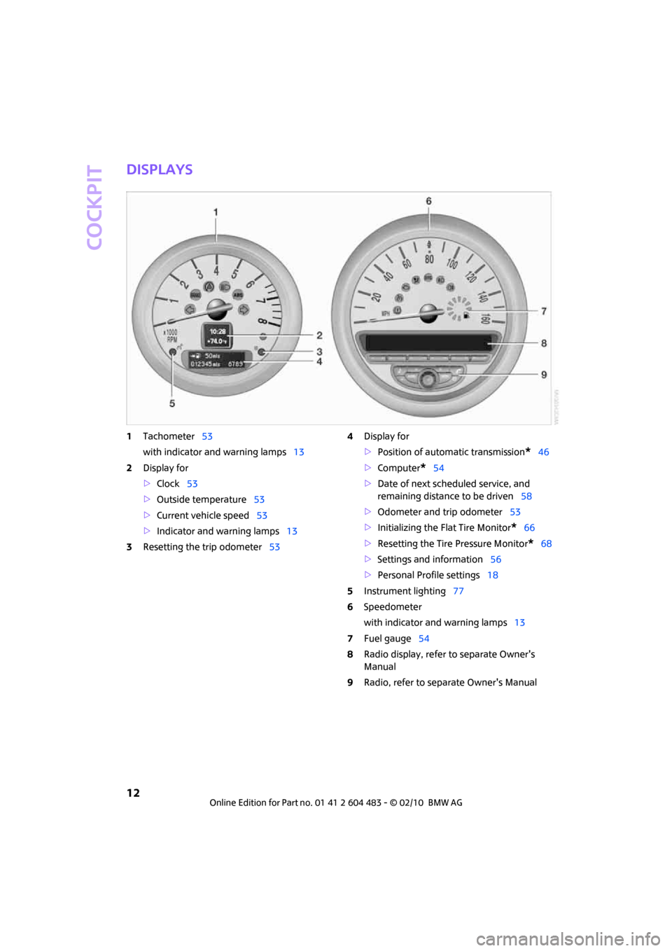
1Tachometer53
with indicator and warning lamps13
2Display for
>Clock53
>Outside temperature53
>Current vehicle speed53
>Indicator and warning lamps13
3Resetting the trip odometer534Display for
>Position of automatic transmission
*46
>Computer
*54
>Date of next scheduled service, and
remaining distance to be driven58
>Odometer and trip odometer53
>Initializing the Flat Tire Monitor
*66
>Resetting the Tire Pressure Monitor
*68
>Settings and information56
>Personal Profile settings18
5Instrument lighting77
6Speedometer
with indicator and warning lamps13
7Fuel gauge54
8Radio display, refer to separate Owner's
Manual
9Radio, refer to separate Owner's Manual
Page 24 of 174
Opening and closing
22
Malfunctions
The remote control may malfunction due to
local radio waves. If this occurs, unlock and lock
the car at the door lock with the integrated key.
If the car can no longer be locked with a remote
control, the battery in the remote control is dis-
charged. Use this remote control during an
extended drive; this will recharge the battery,
page18.
For US owners only
The transmitter and receiver units comply with
part 15 of the FCC/Federal Communications
Commission regulations. Operation is governed
by the following:
FCC ID:
LX8766S
LX8766E
LX8CAS
Compliance statement:
This device complies with part 15 of the FCC
Rules. Operation is subject to the following two
conditions:
>This device must not cause harmful interfer-
ence, and
>this device must accept any interference
received, including interference that may
cause undesired operation.
Any unauthorized modifications or
changes to these devices could void the
user's authority to operate this equipment.<
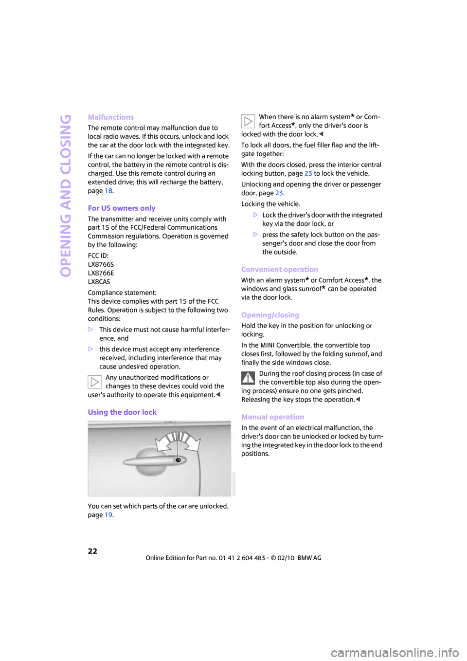
Using the door lock
You can set which parts of the car are unlocked,
page19.When there is no alarm system
* or Com-
fort Access
*, only the driver's door is
locked with the door lock.<
To lock all doors, the fuel filler flap and the lift-
gate together:
With the doors closed, press the interior central
locking button, page23 to lock the vehicle.
Unlocking and opening the driver or passenger
door, page23.
Locking the vehicle.
>Lock the driver's door with the integrated
key via the door lock, or
>press the safety lock button on the pas-
senger's door and close the door from
the outside.
Convenient operation
With an alarm system* or Comfort Access*, the
windows and glass sunroof
* can be operated
via the door lock.
Opening/closing
Hold the key in the position for unlocking or
locking.
In the MINI Convertible, the convertible top
closes first, followed by the folding sunroof, and
finally the side windows close.
During the roof closing process (in case of
the convertible top also during the open-
ing process) ensure no one gets pinched.
Releasing the key stops the operation.<
Manual operation
In the event of an electrical malfunction, the
driver's door can be unlocked or locked by turn-
ing the integrated key in the door lock to the end
positions.
Page 29 of 174
REFERENCEAT A GLANCE CONTROLS DRIVING TIPS MOBILITY
27
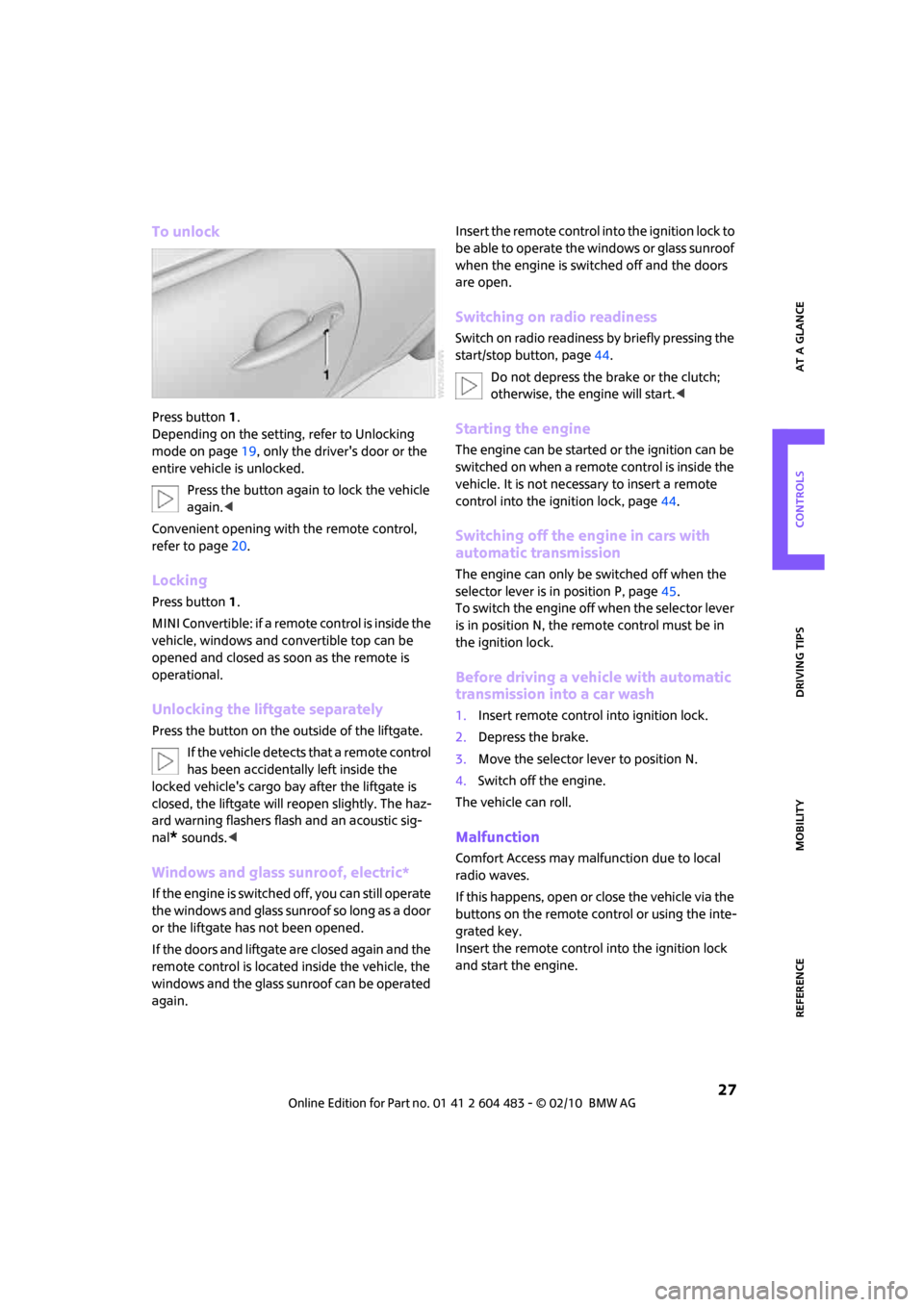
To unlock
Press button 1.
Depending on the setting, refer to Unlocking
mode on page19, only the driver's door or the
entire vehicle is unlocked.
Press the button again to lock the vehicle
again.<
Convenient opening with the remote control,
refer to page20.
Locking
Press button 1.
MINI Convertible: if a remote control is inside the
vehicle, windows and convertible top can be
opened and closed as soon as the remote is
operational.
Unlocking the liftgate separately
Press the button on the outside of the liftgate.
If the vehicle detects that a remote control
has been accidentally left inside the
locked vehicle's cargo bay after the liftgate is
closed, the liftgate will reopen slightly. The haz-
ard warning flashers flash and an acoustic sig-
nal
* sounds.<
Windows and glass sunroof, electric*
If the engine is switched off, you can still operate
the windows and glass sunroof so long as a door
or the liftgate has not been opened.
If the doors and liftgate are closed again and the
remote control is located inside the vehicle, the
windows and the glass sunroof can be operated
again.Insert the remote control into the ignition lock to
be able to operate the windows or glass sunroof
when the engine is switched off and the doors
are open.
Switching on radio readiness
Switch on radio readiness by briefly pressing the
start/stop button, page44.
Do not depress the brake or the clutch;
otherwise, the engine will start.<
Starting the engine
The engine can be started or the ignition can be
switched on when a remote control is inside the
vehicle. It is not necessary to insert a remote
control into the ignition lock, page44.
Switching off the engine in cars with
automatic transmission
The engine can only be switched off when the
selector lever is in position P, page45.
To switch the engine off when the selector lever
is in position N, the remote control must be in
the ignition lock.
Before driving a vehicle with automatic
transmission into a car wash
1.Insert remote control into ignition lock.
2.Depress the brake.
3.Move the selector lever to position N.
4.Switch off the engine.
The vehicle can roll.
Malfunction
Comfort Access may malfunction due to local
radio waves.
If this happens, open or close the vehicle via the
buttons on the remote control or using the inte-
grated key.
Insert the remote control into the ignition lock
and start the engine.
Page 46 of 174

Driving
44
Driving
Ignition lock
Inserting the key into the ignition lock
Insert the key all the way into the ignition lock.
Radio readiness
Individual electrical consumers can operate.
Removing the key from the ignition lock
Press in the key briefly. It is ejected slightly.
At the same time:
>The ignition is switched off if it was on
beforehand.
Automatic transmission
You cannot take out the key unless the selector
lever is in the P position: interlock.
Start/stop button
Press the start/stop button to switch radio readi-
ness or the ignition on and off. Do not depress
the brake or clutch while doing so.When you press the start/stop button and
depress the clutch if the car has manual
transmission or the brake if the car has auto-
matic transmission, the engine starts.<
Radio readiness
Individual electrical consumers can operate. The
time and outside temperature are displayed in
the tachometer.
Radio readiness is switched off automatically:
>When the key is removed from the ignition
lock
>When using Comfort Access
* by pushing
the button on the door handle or the
button on the remote control, refer
to Locking on page27
>after a certain has elapsed
Ignition on
Most indicator and warning lamps in indicator
area 1, page13, light up for varying lengths of
time.
When the engine is off, switch off the igni-
tion and any unnecessary electrical con-
sumers in order to preserve the battery.<
Radio readiness and ignition off
All indicator and warning lamps in the displays
go out.
The ignition automatically turns off
* when the
driver's door is opened. Pressing the start/stop
button again switches the ignition back on.
The ignition is not switched off in situations such
as the following:
>The clutch or brake is depressed
>The low beams are switched on
Page 63 of 174

REFERENCEAT A GLANCE CONTROLS DRIVING TIPS MOBILITY
61
6.Wait for the display to change to minutes.
7.Press the button to set the minutes.
8.Wait for the display to change.
The settings are stored.
Date
Setting the date
To set the dd/mm or mm/dd date format, refer
to Formats and units of measure on page57.
1.Briefly press the button in the turn indicator
lever repeatedly until "SET/INFO" is dis-
played.
2.Press and hold the button until the display
changes.
3.Briefly press the button repeatedly until the
symbol and "SET" are displayed.
4.Press and hold the button until the display
changes.
5.Press the button to set the day of the month.
6.Wait for the display to change to month.
7.Set the month and year in the same way.
8.Wait for the display to change.
The settings are stored.
Check Control
The concept
The Check Control monitors vehicle functions
and alerts you to any malfunctions in the sys-
tems monitored. Check Control messages
involve indicator or warning lamps in the dis-
plays and, in some circumstances, an acoustic
signal. To adjust the volume of the signal, refer
to the Owner's Manual for Radio.
Indicator and warning lamps can light up in var-
ious combinations and colors in the indicator
areas 1 and2.
What to do in case of a malfunction
The meaning of each lamp in the event of a mal-
function and tips on how to respond are listed
starting on page140.
Hiding Check Control messages
Press the button in the turn indicator lever.
Some Check Control messages are displayed
until the malfunctions have been rectified. They
cannot be hidden. If several malfunctions occur
at the same time, they are displayed in succes-
sion.
Page 65 of 174
REFERENCEAT A GLANCE CONTROLS DRIVING TIPS MOBILITY
63
Technology for driving comfort and
safety
Park Distance Control
PDC*
The concept
PDC assists you with parking backwards. Acous-
tic signals warn you of the presence of an object
behind the vehicle. To measure the distance,
there are four ultrasonic sensors in either
bumper.
However, an acoustic warning does not sound
until an object is approx. 24 in/60 cm from the
corner sensors, or approx. 5 ft/1.50 m from the
center sensors.
PDC is a parking aid that can indicate
objects when they are approached slowly,
as is usually the case when parking. Avoid
approaching an object at high speed; otherwise,
physical circumstances may lead to the system
warning being issued too late.<
Automatic mode
With the engine running or the ignition switched
on, the system is activated automatically after
approx. 1 second when you engage reverse gear
or move the automatic transmission selector
lever to position R. Wait this short period before
driving.
Acoustic signals
As the distance between vehicle and object
decreases, the intervals between the tones
become shorter. If the distance to the nearest
object falls to below roughly 1 ft/30 cm, then a
continuous tone sounds.
If the distance remains constant, e.g. when driv-
ing parallel to a wall, the acoustic signal stops
after approx. 3 seconds.
Adjustments
The volume of the acoustic signals can be
adjusted, refer to the Owner's Manual for Radio.
Malfunction
Indicator lamp comes on: PDC has
failed. Have the system checked.
To avoid this problem, keep the sensors
clean and free of ice or snow in order to ensure
that they will continue to operate effectively.
When using a high-pressure cleaner, do not
direct the jet toward the sensors for lengthy
periods and only spray from a distance of at least
4in/10cm.
System limitations
Even with PDC, final responsibility for esti-
mating the distance between the vehicle
and any obstructions always remains with the
driver. Sensors, too, have blind spots in which
objects cannot be detected. Moreover, ultra-
sonic detection can reach its physical limits with
objects such as trailer tow bars and couplings,
thin and wedge-shaped objects, etc. Low
objects already indicated, such as curbs, may
enter the sensors' blind spots before or after a
continuous audible signal is given. Higher, pro-
truding objects, such as wall ledges, may not be
detectable. Therefore, always drive cautiously;
otherwise, there is a risk of personal injury or
property damage. Loud sound sources outside
or inside the car can drown out the PDC signal.<
Driving stability control
systems
Your MINI has a number of systems that help to
maintain the vehicle's stability even in adverse
driving conditions.
The laws of physics cannot be repealed,
even with driving stability control systems.
An appropriate driving style always remains the
responsibility of the driver. Therefore do not
reduce the additional safety margin by engaging
in hazardous driving thereby running the risk of
an accident.<
Page 70 of 174
Technology for driving comfort and safety
68
Tire Pressure Monitor
TPM*
The concept
TPM checks the tire pressure in the four
mounted tires during driving. The system noti-
fies you if there is a significant loss of pressure in
one or more tires.
Functional requirement
In order to assure the reliable reporting of a flat
tire, the system must be reset while all tire infla-
tion pressures are correct.
Always use wheels with TPM electronics. Other-
wise, the system may malfunction.
Each time a tire inflation pressure has
been corrected or a wheel or tire has been
changed, reset the system.<
System limitations
TPM cannot warn you in advance of sud-
d e n s e v e r e t i r e d a m a g e c a u s e d b y o u t s i d e
influences.<
The system does not work correctly if it has not
been reset; for example, a flat tire may be indi-
cated even though the tire inflation pressures
are correct.
The system is inactive and cannot indicate a flat
tire if a wheel without TPM electronics, such as a
compact spare wheel
*, has been mounted, or if
TPM is temporarily malfunctioning due to other
systems or devices using the same radio fre-
quency.
Resetting the system
Each time a tire inflation pressure has
been corrected or a wheel or tire has been
changed, reset the system.<
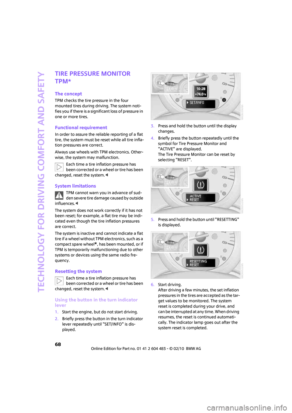
Using the button in the turn indicator
lever
1.Start the engine, but do not start driving.
2.Briefly press the button in the turn indicator
lever repeatedly until "SET/INFO" is dis-
played.3.Press and hold the button until the display
changes.
4.Briefly press the button repeatedly until the
symbol for Tire Pressure Monitor and
"ACTIVE" are displayed.
The Tire Pressure Monitor can be reset by
selecting "RESET".
5.Press and hold the button until "RESETTING"
is displayed.
6.Start driving.
After driving a few minutes, the set inflation
pressures in the tires are accepted as the tar-
get values to be monitored. The system
reset is completed during your drive, and
c a n b e i n t e r r u p t e d a t a n y t i m e . W h e n d r i v i n g
resumes, the reset is continued automati-
cally. The indicator lamp goes out after the
system reset is completed.
Page 71 of 174
REFERENCEAT A GLANCE CONTROLS DRIVING TIPS MOBILITY
69
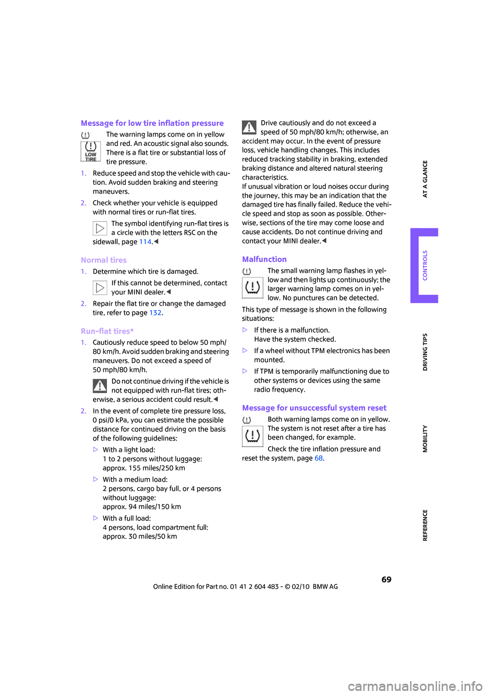
Message for low tire inflation pressure
The warning lamps come on in yellow
and red. An acoustic signal also sounds.
There is a flat tire or substantial loss of
tire pressure.
1.Reduce speed and stop the vehicle with cau-
tion. Avoid sudden braking and steering
maneuvers.
2.Check whether your vehicle is equipped
with normal tires or run-flat tires.
The symbol identifying run-flat tires is
a circle with the letters RSC on the
sidewall, page114.<
Normal tires
1.Determine which tire is damaged.
If this cannot be determined, contact
your MINI dealer.<
2.Repair the flat tire or change the damaged
tire, refer to page132.
Run-flat tires*
1.Cautiously reduce speed to below 50 mph/
80 km/h. Avoid sudden braking and steering
maneuvers. Do not exceed a speed of
50 mph/80 km/h.
Do not continue driving if the vehicle is
not equipped with run-flat tires; oth-
erwise, a serious accident could result.<
2.In the event of complete tire pressure loss,
0 psi/0 kPa, you can estimate the possible
distance for continued driving on the basis
of the following guidelines:
>With a light load:
1 to 2 persons without luggage:
approx. 155 miles/250 km
>With a medium load:
2 persons, cargo bay full, or 4 persons
without luggage:
approx. 94 miles/150 km
>With a full load:
4 persons, load compartment full:
approx. 30 miles/50 kmDrive cautiously and do not exceed a
speed of 50 mph/80 km/h; otherwise, an
accident may occur. In the event of pressure
loss, vehicle handling changes. This includes
reduced tracking stability in braking, extended
braking distance and altered natural steering
characteristics.
If unusual vibration or loud noises occur during
the journey, this may be an indication that the
damaged tire has finally failed. Reduce the vehi-
cle speed and stop as soon as possible. Other-
wise, sections of the tire may come loose and
cause accidents. Do not continue driving and
contact your MINI dealer.<
Malfunction
The small warning lamp flashes in yel-
low and then lights up continuously; the
larger warning lamp comes on in yel-
low. No punctures can be detected.
This type of message is shown in the following
situations:
>If there is a malfunction.
Have the system checked.
>If a wheel without TPM electronics has been
mounted.
>If TPM is temporarily malfunctioning due to
other systems or devices using the same
radio frequency.
Message for unsuccessful system reset
Both warning lamps come on in yellow.
The system is not reset after a tire has
been changed, for example.
Check the tire inflation pressure and
reset the system, page68.