engine MINI COOPER 2002 Service Repair Manual
[x] Cancel search | Manufacturer: MINI, Model Year: 2002, Model line: COOPER, Model: MINI COOPER 2002Pages: 1079, PDF Size: 70.32 MB
Page 25 of 1079

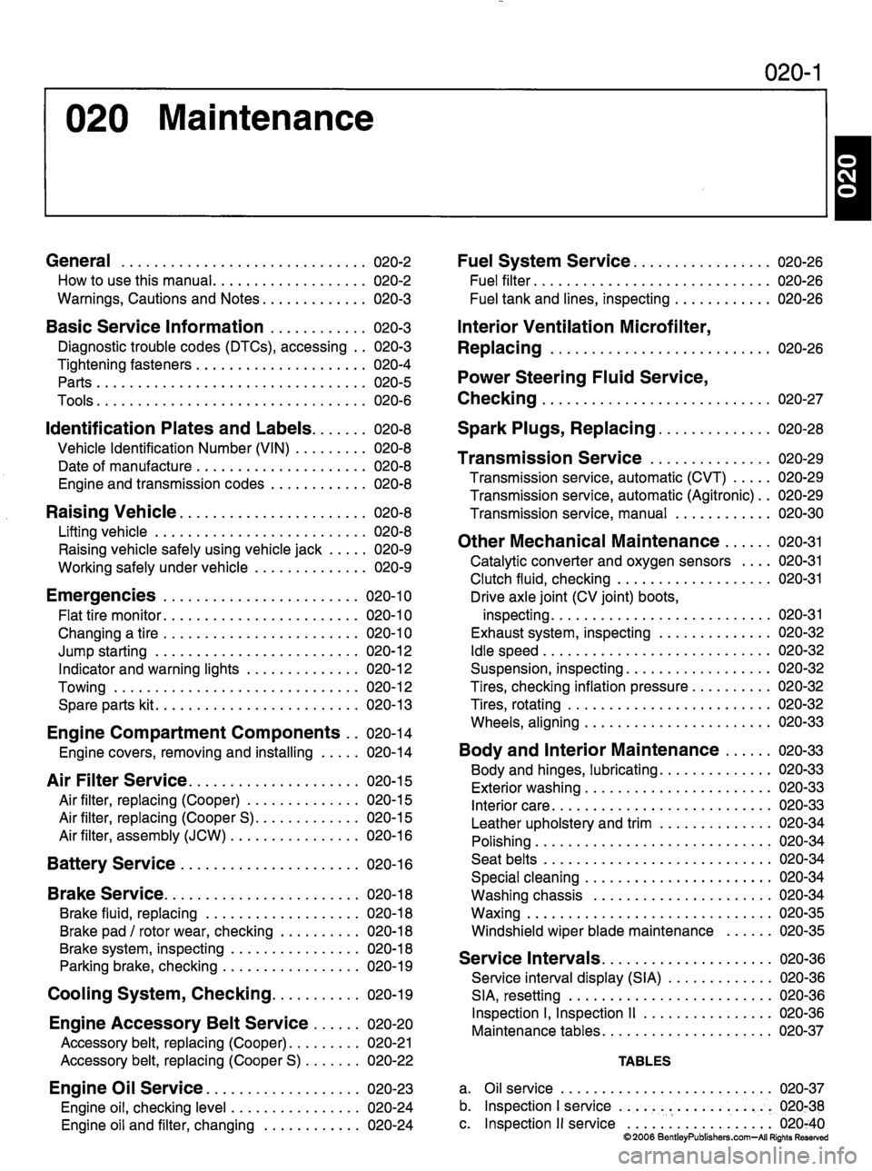
020 Maintenance
020-1
General 020-2
H o w t o u s e t h i s m a n u a l 0 2 0 - 2
W a r n i n g s , C a u t i o n s a n d N o t e s 0 2 0 - 3
B a s i c S e r v i c e I n f o r m a t i o n 0 2 0 - 3
Diagnostic trouble codes (DTCs), accessing .. 020-3
T i g h t e n i n g f a s t e n e r s 0 2 0 - 4
P a r t s 0 2 0 - 5
T o o l s 0 2 0 - 6
I d e n t i fi c a t i o n P l a t e s a n d L a b e l s 0 2 0 - 8
V e h i c l e I d e n t i fi c a t i o n N u m b e r ( V I N ) 0 2 0 - 8
Date of manufacture 020-8
E n g i n e a n d t r a n s m i s s i o n c o d e s 0 2 0 - 8
Raising Vehicle 020-8
Lifting vehicle 020-8
Raising vehicle safely using vehicle jack 020-9
W o r k i n g s a f e l y u n d e r v e h i c l e 0 2 0 - 9
E m e r g e n c i e s 0 2 0 - 1 0
F l a t t i r e m o n i t o r 0 2 0 - 1 0
Changing a tire 020-10
Jump starting 020-12 I n d i c a t o r a n d w a r n i n g l i g h t s 0 2 0 - 1 2
To w i n g 0 2 0 - 1 2
S p a r e p a r t s k i t 0 2 0 - 1 3
Engine Compartment Components .. 020-14
Engine covers, removing and installing 020-14
A i r F i l t e r S e r v i c e 0 2 0 - 1 5
A i r fi l t e r , r e p l a c i n g ( C o o p e r ) 0 2 0 - 1 5
A i r fi l t e r , r e p l a c i n g ( C o o p e r S ) 0 2 0 - 1 5
A i r fi l t e r , a s s e m b l y ( J C W ) 0 2 0 - 1 6
B a t t e r y S e r v i c e 0 2 0 - 1 6
Brake Service 020-18
Brake fluid, replacing 020-18
B r a k e p a d / r o t o r w e a r , c h e c k i n g 0 2 0 - 1 8
Brake system, inspecting 020-18
Parking brake, checking 020-19
Cooling System, Checking 020-19
E n g i n e A c c e s s o r y B e l t S e r v i c e 0 2 0 - 2 0
A c c e s s o r y b e l t , r e p l a c i n g ( C o o p e r ) 0 2 0 - 2 1
Accessory belt, replacing (Cooper S) 020-22
Engine Oil Service 020-23
Engine oil, checking level 020-24
Engine oil and filter, changing 020-24
F u e l S y s t e m S e r v i c e 0 2 0 - 2 6
F u e l fi l t e r 0 2 0 - 2 6
F u e l t a n k a n d l i n e s , i n s p e c t i n g 0 2 0 - 2 6
Interior Ventilation Microfilter,
Replacing 020-26
Power Steering Fluid Service,
Checking 020-27
S p a r k P l u g s , R e p l a c i n g 0 2 0 - 2 8
Transmission Service 020-29
Transmission service, automatic (CVT) 020-29
Transmission service, automatic (Agitronic).. 020-29
Transmission service, manual 020-30
O t h e r M e c h a n i c a l M a i n t e n a n c e 0 2 0 - 3 1
Catalytic converter and oxygen sensors .... 020-31
Clutch fluid, checking 020-31 Drive axle joint (CV joint) boots,
inspecting 020-31
Exhaust system, inspecting 020-32
Idle speed 020-32
Suspension, inspecting 020-32
Tires, checking inflation pressure 020-32
Tires, rotating 020-32
Wheels, aligning 020-33
B o d y a n d I n t e r i o r M a i n t e n a n c e 0 2 0 - 3 3
B o d y a n d h i n g e s , l u b r i c a t i n g 0 2 0 - 3 3
E x t e r i o r w a s h i n g 0 2 0 - 3 3
I n t e r i o r c a r e 0 2 0 - 3 3
L e a t h e r u p h o l s t e r y a n d t r i m 0 2 0 - 3 4
Polishing 020-34
S e a t b e l t s 0 2 0 - 3 4
Special cleaning 020-34
W a s h i n g c h a s s i s 0 2 0 - 3 4
Waxing 020-35
W i n d s h i e l d w i p e r b l a d e m a i n t e n a n c e 0 2 0 - 3 5
S e r v i c e I n t e r v a l s 0 2 0 - 3 6
S e r v i c e i n t e r v a l d i s p l a y ( S I A ) 0 2 0 - 3 6
SIA, resetting 020-36
Inspection I, Inspection II 020-36
M a i n t e n a n c e t a b l e s 0 2 0 - 3 7
TA B L E S
a. Oil service 020-37
b. Inspection I service 020-38
c. Inspection II service 020-40
©2006 BentleyPublishers.com—All Rights Reserved
Page 225 of 1079

130-1
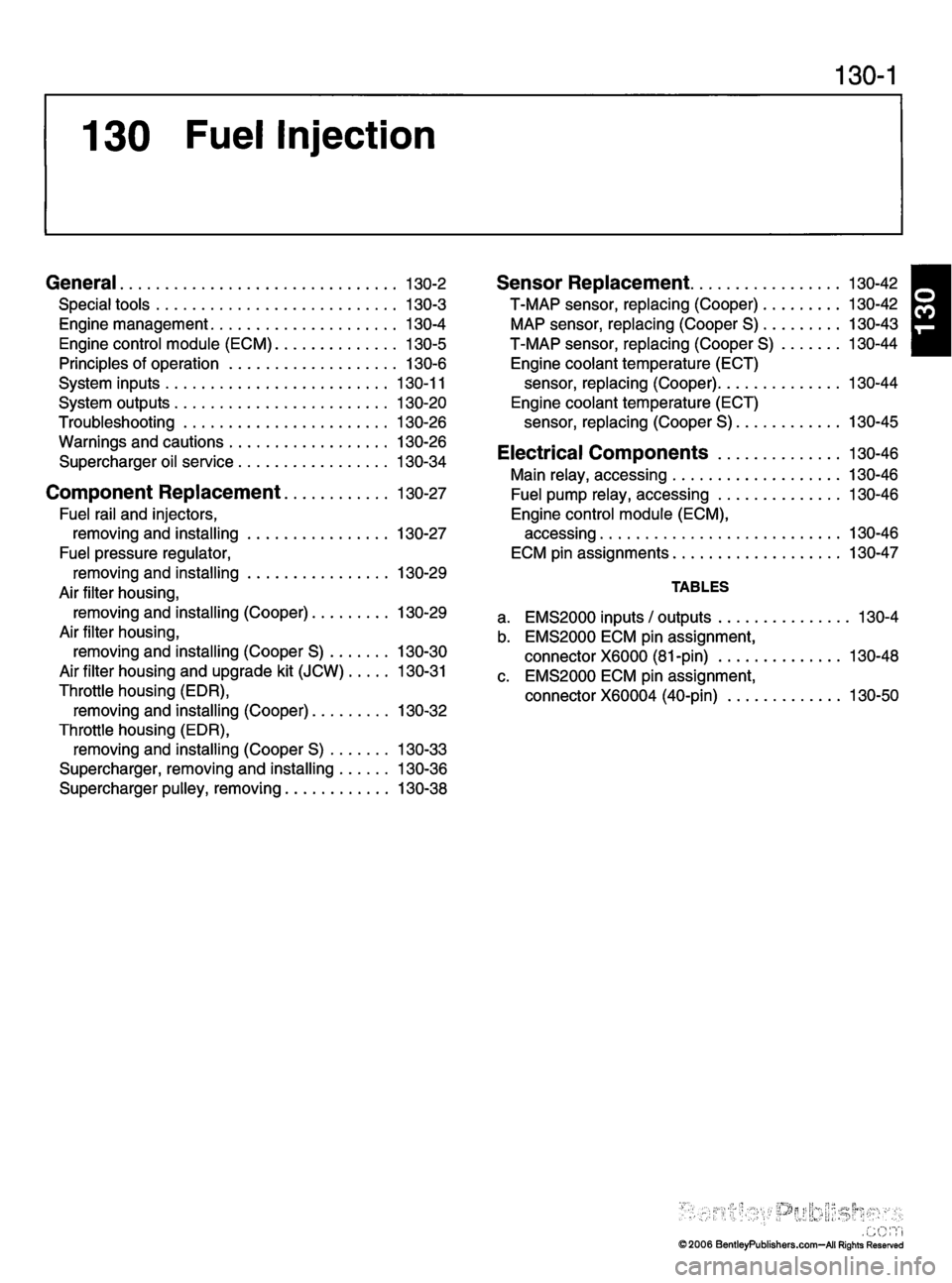
130 Fuel Injection
General 130-2
S p e c i a l t o o l s 1 3 0 - 3
Engine management 130-4
E n g i n e c o n t r o l m o d u l e ( E C M ) 1 3 0 - 5
P r i n c i p l e s o f o p e r a t i o n 1 3 0 - 6
S y s t e m i n p u t s 1 3 0 - 1 1
S y s t e m o u t p u t s 1 3 0 - 2 0
Troubleshooting 130-26
W a r n i n g s a n d c a u t i o n s 1 3 0 - 2 6
S u p e r c h a r g e r o i l s e r v i c e 1 3 0 - 3 4
Component Replacement 130-27Fuel rail and injectors,
removing and installing 130-27
Fuel pressure regulator,
removing and installing 130-29
Air filter housing,
r e m o v i n g a n d i n s t a l l i n g ( C o o p e r ) 1 3 0 - 2 9
Air filter housing,
r e m o v i n g a n d i n s t a l l i n g ( C o o p e r S ) 1 3 0 - 3 0
Air filter housing and upgrade kit (JCW) 130-31
Throttle housing (EDR),
r e m o v i n g a n d i n s t a l l i n g ( C o o p e r ) 1 3 0 - 3 2
Throttle housing (EDR),
r e m o v i n g a n d i n s t a l l i n g ( C o o p e r S ) 1 3 0 - 3 3
Supercharger, removing and installing 130-36
S u p e r c h a r g e r p u l l e y , r e m o v i n g 1 3 0 - 3 8
S e n s o r R e p l a c e m e n t 1 3 0 - 4 2
T - M A P s e n s o r , r e p l a c i n g ( C o o p e r ) 1 3 0 - 4 2 M A P s e n s o r, r e p l a c i n g ( C o o p e r S ) 1 3 0 - 4 3
T- M A P s e n s o r, r e p l a c i n g ( C o o p e r S ) 1 3 0 - 4 4
Engine coolant temperature (ECT) s e n s o r , r e p l a c i n g ( C o o p e r ) 1 3 0 - 4 4
Engine coolant temperature (ECT) s e n s o r , r e p l a c i n g ( C o o p e r S ) 1 3 0 - 4 5
E l e c t r i c a l C o m p o n e n t s 1 3 0 - 4 6
Main relay, accessing 130-46
Fuel pump relay, accessing 130-46
Engine control module (ECM),accessing 130-46
E C M p i n a s s i g n m e n t s 1 3 0 - 4 7
TA B L E S
a . E M S 2 0 0 0 i n p u t s / o u t p u t s 1 3 0 - 4
b. EMS2000 ECM pin assignment,
c o n n e c t o r X 6 0 0 0 ( 8 1 - p i n ) 1 3 0 - 4 8
c. EMS2000 ECM pin assignment, c o n n e c t o r X 6 0 0 0 4 ( 4 0 - p i n ) 1 3 0 - 5 0
1
©2006 BentleyPublishers.com—All Rights Reserved
Page 766 of 1079

ELE-1
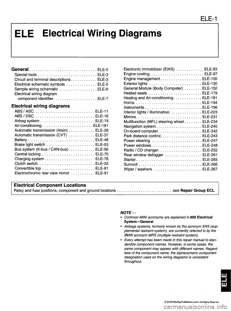
General ele-2
S p e c i a l t o o l s E L E - 3
C i r c u i t a n d t e r m i n a l d e s c r i p t i o n s E L E - 3
E l e c t r i c a l s c h e m a t i c s y m b o l s E L E - 5
S a m p l e w i r i n g s c h e m a t i c E L E - 6
Electrical wiring diagram
c o m p o n e n t i d e n t i fi e r E L E - 7
Electrical wiring diagrams
ABS/ASC ELE-11
A B S / D S C E L E - 1 6
A i r b a g s y s t e m E L E - 1 9
Air-conditioning ELE-181
A u t o m a t i c t r a n s m i s s i o n ( A i s i n ) E L E - 2 8
A u t o m a t i c t r a n s m i s s i o n ( C V T ) E L E - 3 7
B a t t e r y E L E - 4 8
Brake light switch ELE-53
B u s s y s t e m ( K - b u s / C A N - b u s ) E L E - 5 6
Central locking ELE-70
C h a r g i n g s y s t e m E L E - 7 8
Clutch switch ELE-53
Convertible top ELE-81 E l e c t r o c h r o m i c r e a r v i e w m i r r o r E L E - 9 1 E l e c t r o n i c i m m o b i l i z e r ( E W S ) E L E - 9 3
Engine cooling ELE-97
Engine management ELE-100
E x t e r i o r l i g h t s E L E - 1 3 0
G e n e r a l M o d u l e ( B o d y C o m p u t e r ) E L E - 1 5 2
H e a t e d s e a t s E L E - 1 7 9
Heating and Air-conditioning ELE-181
H o r n s
E L E - 1 9 4
I n s t r u m e n t s E L E - 1 9 6
I n t e r i o r l i g h t s / i l l u m i n a t i o n E L E - 2 2 3
M i r r o r s E L E - 2 3 1
M u l t i f u n c t i o n ( M F L ) s t e e r i n g w h e e l E L E - 2 3 4
N a v i g a t i o n s y s t e m E L E - 2 4 0
O n - b o a r d c o m p u t e r E L E - 2 4 2
P a r k d i s t a n c e c o n t r o l E L E - 2 4 3
P o w e r s t e e r i n g E L E - 2 4 7
P o w e r w i n d o w s E L E - 2 4 8 R a d i o / C D c h a n g e r E L E - 2 5 2
R e a r w i n d o w d e f o g g e r E L E - 2 6 1
S t a r t e r E L E - 2 6 5
Sunroof ELE-266
W i p e r / w a s h e r s E L E - 2 6 7
Electrical Component Locations
Relay and fuse positions, component and ground locations .see Repair Group ECL
NOTE—
• Common MINI acronyms are explained in 600 Electrical System—General.
• Airbags systems, formerly known by the acronym SRS (sup
plemental restraint system), are currently referred to by the
BMW acronym MRS (multiple restraint system).
• Every attempt has been made in this repair manual to stan
dardize component names. However, in some cases, the
same component may appear with different names. Regard
less of the component name, the alphanumeric component
designation used on the wiring diagrams is consistentthroughout.
1
©2006 BentleyPublishers.com—All Rights Reserved
Page 886 of 1079

Electrical Wiring Diagrams ELE-121
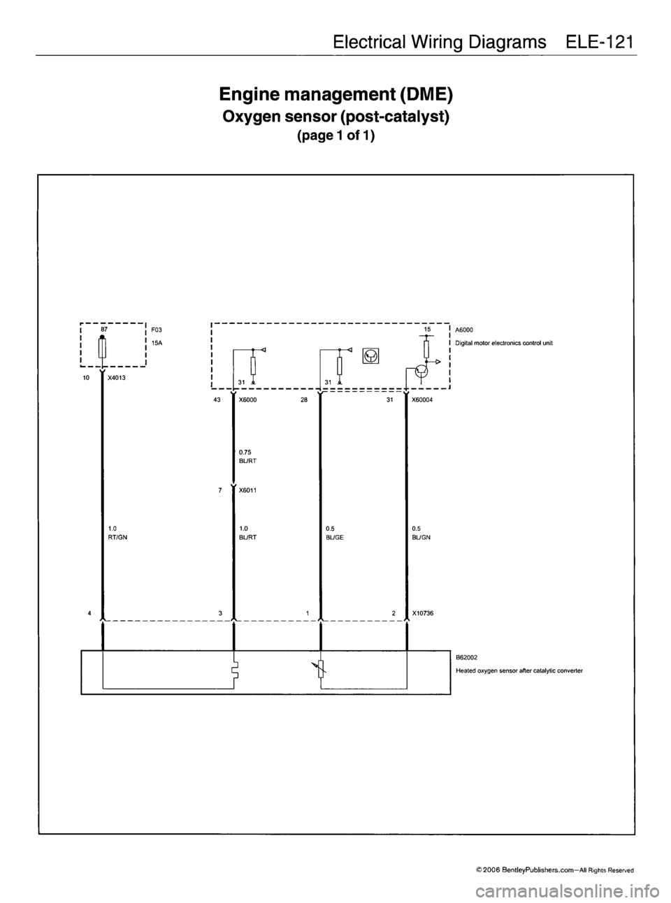
Engine management (DME) Oxygen sensor (post-catalyst)
(pagel of 1)
Of
I
1.0
RT/GN F03
15A
0.75
BURT
1.0
BL/RT
f
0.5
BL/GE0.5
BL/GN
2 X 1 0 7 3 6 A6000
Digital motor electronics control unit
B62002
Heated oxygen sensor after catalytic converter
©2006 BentleyPublishers.com—All Rights Reserved