fuse MINI COOPER 2002 Service Repair Manual
[x] Cancel search | Manufacturer: MINI, Model Year: 2002, Model line: COOPER, Model: MINI COOPER 2002Pages: 1079, PDF Size: 70.32 MB
Page 732 of 1079

ECL-1
ECL Electrical Component Locations
General ecl-2
S p e c i a l t o o l s E C L - 2
E l e c t r i c a l s y s t e m s a f e t y p r e c a u t i o n s E C L - 3
E l e c t r i c a l C o m p o n e n t s e c l - 3
F u s e l o c a t i o n s E C L - 1 3
R e l a y p a n e l s E C L - 1 6
G r o u n d l o c a t i o n s E C L - 1 7
C o m p o n e n t l o c a t i o n i l l u s t r a t i o n s E C L - 2 1
E n g i n e c o m p a r t m e n t c o m p o n e n t s E C L - 2 2
C o m p o n e n t s u n d e r n e a t h v e h i c l e E C L - 2 6
Heating and A/C components
( v e h i c l e i n t e r i o r ) E C L - 2 8 C o m p o n e n t s u n d e r d a s h b o a r d E C L - 2 9
V e h i c l e i n t e r i o r c o m p o n e n t s E C L - 3 0
Convertible top and additional
i n t e r i o r c o m p o n e n t s E C L - 3 2TA B L E S
Electrical component location table ECL-3F u s e p a n e l 2 , b e h i n d l e f t k i c k p a n e l E C L - 1 3
Fuse panel 3, next to left strut tower ECL-15
G r o u n d l o c a t i o n s E C L - 1 8
*&
©2006 BentleyPublishers.com-AII Rights Reserved
Page 766 of 1079

ELE-1
General ele-2
S p e c i a l t o o l s E L E - 3
C i r c u i t a n d t e r m i n a l d e s c r i p t i o n s E L E - 3
E l e c t r i c a l s c h e m a t i c s y m b o l s E L E - 5
S a m p l e w i r i n g s c h e m a t i c E L E - 6
Electrical wiring diagram
c o m p o n e n t i d e n t i fi e r E L E - 7
Electrical wiring diagrams
ABS/ASC ELE-11
A B S / D S C E L E - 1 6
A i r b a g s y s t e m E L E - 1 9
Air-conditioning ELE-181
A u t o m a t i c t r a n s m i s s i o n ( A i s i n ) E L E - 2 8
A u t o m a t i c t r a n s m i s s i o n ( C V T ) E L E - 3 7
B a t t e r y E L E - 4 8
Brake light switch ELE-53
B u s s y s t e m ( K - b u s / C A N - b u s ) E L E - 5 6
Central locking ELE-70
C h a r g i n g s y s t e m E L E - 7 8
Clutch switch ELE-53
Convertible top ELE-81 E l e c t r o c h r o m i c r e a r v i e w m i r r o r E L E - 9 1 E l e c t r o n i c i m m o b i l i z e r ( E W S ) E L E - 9 3
Engine cooling ELE-97
Engine management ELE-100
E x t e r i o r l i g h t s E L E - 1 3 0
G e n e r a l M o d u l e ( B o d y C o m p u t e r ) E L E - 1 5 2
H e a t e d s e a t s E L E - 1 7 9
Heating and Air-conditioning ELE-181
H o r n s
E L E - 1 9 4
I n s t r u m e n t s E L E - 1 9 6
I n t e r i o r l i g h t s / i l l u m i n a t i o n E L E - 2 2 3
M i r r o r s E L E - 2 3 1
M u l t i f u n c t i o n ( M F L ) s t e e r i n g w h e e l E L E - 2 3 4
N a v i g a t i o n s y s t e m E L E - 2 4 0
O n - b o a r d c o m p u t e r E L E - 2 4 2
P a r k d i s t a n c e c o n t r o l E L E - 2 4 3
P o w e r s t e e r i n g E L E - 2 4 7
P o w e r w i n d o w s E L E - 2 4 8 R a d i o / C D c h a n g e r E L E - 2 5 2
R e a r w i n d o w d e f o g g e r E L E - 2 6 1
S t a r t e r E L E - 2 6 5
Sunroof ELE-266
W i p e r / w a s h e r s E L E - 2 6 7
Electrical Component Locations
Relay and fuse positions, component and ground locations .see Repair Group ECL
NOTE—
• Common MINI acronyms are explained in 600 Electrical System—General.
• Airbags systems, formerly known by the acronym SRS (sup
plemental restraint system), are currently referred to by the
BMW acronym MRS (multiple restraint system).
• Every attempt has been made in this repair manual to stan
dardize component names. However, in some cases, the
same component may appear with different names. Regard
less of the component name, the alphanumeric component
designation used on the wiring diagrams is consistentthroughout.
1
©2006 BentleyPublishers.com—All Rights Reserved
Page 916 of 1079

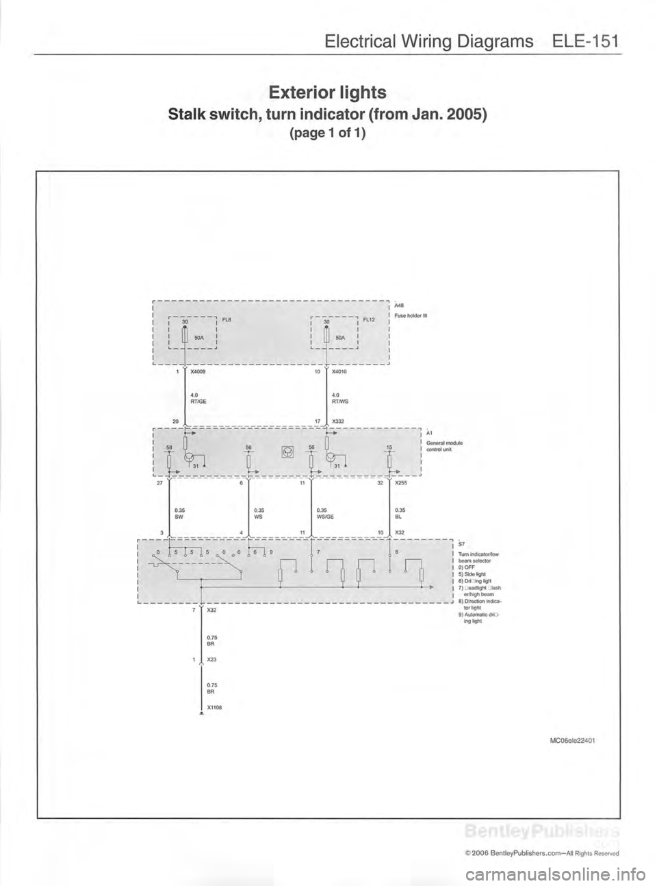
Electrical Wiring Diagrams ELE-151
Exterior lights
Stalk switch, turn indicator (from Jan. 2005)
(pagel of 1)
A48
Fuse holder II
General module
control unitS7
Turn indicator/lowbeam selector
0)OFF 5) Side light
6) Dri -ing light
7) jeadlight :tash er/high beam
8) Direction Indica tor light
9} Automatic dri;> ing light
MC06ele22401
C S f c ■■ !
'£ 2006 BentleyPublishers.com-AII Rights Reserved
Page 948 of 1079
![MINI COOPER 2002 Service Repair Manual Electrical Wiring Diagrams ELE-183
Heating and A/C
Power supply (from March 2003 to Sept. 2005)
r A47■"]
Fuse
holder
II S241
Switch panel
ii
, " J F 2 9
l I
5A I 1 r " " K 4
1
1
1 1
1 MINI COOPER 2002 Service Repair Manual Electrical Wiring Diagrams ELE-183
Heating and A/C
Power supply (from March 2003 to Sept. 2005)
r A47■"]
Fuse
holder
II S241
Switch panel
ii
, " J F 2 9
l I
5A I 1 r " " K 4
1
1
1 1
1](/img/30/57083/w960_57083-947.png)
Electrical Wiring Diagrams ELE-183
Heating and A/C
Power supply (from March 2003 to Sept. 2005)
r A47■"]
Fuse
holder
II S241
Switch panel
ii
, " J F 2 9
'l I
5A I 1 r " " K 4
1
1
1 1
1 1
1 i r
i
1 1
1 1
1 1
I i
2' X1879
4 ' X10207
4
-' X10201
X10659
4.0
RT/GN , F "
2
fX146
4.0 0.50.35
■RT
X01114 14GR/RT
15WS/RT/GE
X1527
<
>——— ▶
0.5
VI/BL/GE
0.75
RT 0.5
GR/RT0.35
WS/GR/GE
9 3 1416X610
*i
1 A11
1
1
lB| Heating and A/C control module
26 ' ' X610
0.5BR/SW
13 ' X1527
0.5BR/SW
X3361
JLBM06ele20763
J2006 BentleyPublishers.com—All Rights Reserved