light MINI COOPER 2002 Service Repair Manual
[x] Cancel search | Manufacturer: MINI, Model Year: 2002, Model line: COOPER, Model: MINI COOPER 2002Pages: 1079, PDF Size: 70.32 MB
Page 346 of 1079

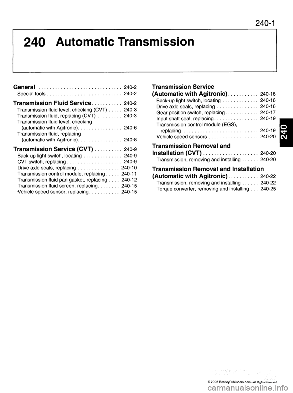
240-1
240 Automatic Transmission
General 240-2
S p e c i a l t o o l s 2 4 0 - 2
Transmission Fluid Service 240-2
Transmission fluid level, checking (CVT) 240-3
Transmission fluid, replacing (CVT) 240-3
Transmission fluid level, checking
( a u t o m a t i c w i t h A g i t r o n i c ) 2 4 0 - 6
Transmission fluid, replacing
( a u t o m a t i c w i t h A g i t r o n i c ) 2 4 0 - 8
T r a n s m i s s i o n S e r v i c e ( C V T ) 2 4 0 - 9
Back-up light switch, locating 240-9
CVT switch, replacing 240-9
Drive axle seals, replacing 240-10
Transmission control module, replacing 240-11
Transmission fluid pan gasket, replacing .... 240-12
Transmission fluid screen, replacing 240-15
Ve h i c l e s p e e d s e n s o r, r e p l a c i n g 2 4 0 - 1 5
Transmission Service
( A u t o m a t i c w i t h A g i t r o n i c ) 2 4 0 - 1 6
Back-up light switch, locating 240-16
Drive axle seals, replacing 240-16
G e a r p o s i t i o n s w i t c h , r e p l a c i n g 2 4 0 - 1 7
Input shaft seal, replacing 240-19
Transmission control module (EGS),
replacing 240-19
V e h i c l e s p e e d s e n s o r s 2 4 0 - 2 0
Transmission Removal and
I n s t a l l a t i o n ( C V T ) 2 4 0 - 2 0
Transmission, removing and installing 240-20
Transmission Removal and Installation
( A u t o m a t i c w i t h A g i t r o n i c ) 2 4 0 - 2 2
Transmission, removing and installing 240-22
To r q u e c o n v e r t e r , r e m o v i n g a n d i n s t a l l i n g . . . 2 4 0 - 2 5
1
©2006 BentleyPublishers.com-AII Rights Reserved
Page 766 of 1079

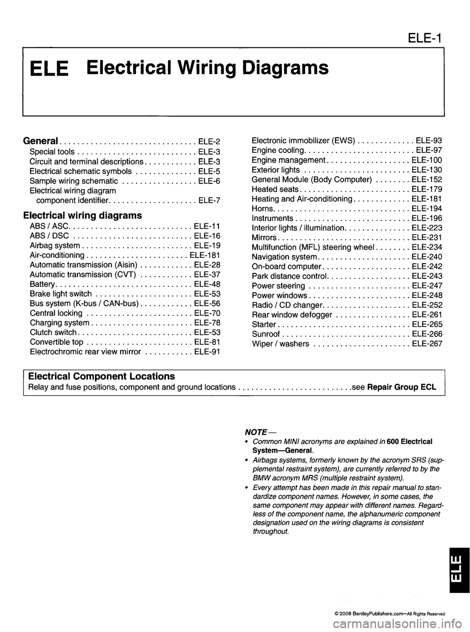
ELE-1
General ele-2
S p e c i a l t o o l s E L E - 3
C i r c u i t a n d t e r m i n a l d e s c r i p t i o n s E L E - 3
E l e c t r i c a l s c h e m a t i c s y m b o l s E L E - 5
S a m p l e w i r i n g s c h e m a t i c E L E - 6
Electrical wiring diagram
c o m p o n e n t i d e n t i fi e r E L E - 7
Electrical wiring diagrams
ABS/ASC ELE-11
A B S / D S C E L E - 1 6
A i r b a g s y s t e m E L E - 1 9
Air-conditioning ELE-181
A u t o m a t i c t r a n s m i s s i o n ( A i s i n ) E L E - 2 8
A u t o m a t i c t r a n s m i s s i o n ( C V T ) E L E - 3 7
B a t t e r y E L E - 4 8
Brake light switch ELE-53
B u s s y s t e m ( K - b u s / C A N - b u s ) E L E - 5 6
Central locking ELE-70
C h a r g i n g s y s t e m E L E - 7 8
Clutch switch ELE-53
Convertible top ELE-81 E l e c t r o c h r o m i c r e a r v i e w m i r r o r E L E - 9 1 E l e c t r o n i c i m m o b i l i z e r ( E W S ) E L E - 9 3
Engine cooling ELE-97
Engine management ELE-100
E x t e r i o r l i g h t s E L E - 1 3 0
G e n e r a l M o d u l e ( B o d y C o m p u t e r ) E L E - 1 5 2
H e a t e d s e a t s E L E - 1 7 9
Heating and Air-conditioning ELE-181
H o r n s
E L E - 1 9 4
I n s t r u m e n t s E L E - 1 9 6
I n t e r i o r l i g h t s / i l l u m i n a t i o n E L E - 2 2 3
M i r r o r s E L E - 2 3 1
M u l t i f u n c t i o n ( M F L ) s t e e r i n g w h e e l E L E - 2 3 4
N a v i g a t i o n s y s t e m E L E - 2 4 0
O n - b o a r d c o m p u t e r E L E - 2 4 2
P a r k d i s t a n c e c o n t r o l E L E - 2 4 3
P o w e r s t e e r i n g E L E - 2 4 7
P o w e r w i n d o w s E L E - 2 4 8 R a d i o / C D c h a n g e r E L E - 2 5 2
R e a r w i n d o w d e f o g g e r E L E - 2 6 1
S t a r t e r E L E - 2 6 5
Sunroof ELE-266
W i p e r / w a s h e r s E L E - 2 6 7
Electrical Component Locations
Relay and fuse positions, component and ground locations .see Repair Group ECL
NOTE—
• Common MINI acronyms are explained in 600 Electrical System—General.
• Airbags systems, formerly known by the acronym SRS (sup
plemental restraint system), are currently referred to by the
BMW acronym MRS (multiple restraint system).
• Every attempt has been made in this repair manual to stan
dardize component names. However, in some cases, the
same component may appear with different names. Regard
less of the component name, the alphanumeric component
designation used on the wiring diagrams is consistentthroughout.
1
©2006 BentleyPublishers.com—All Rights Reserved
Page 916 of 1079

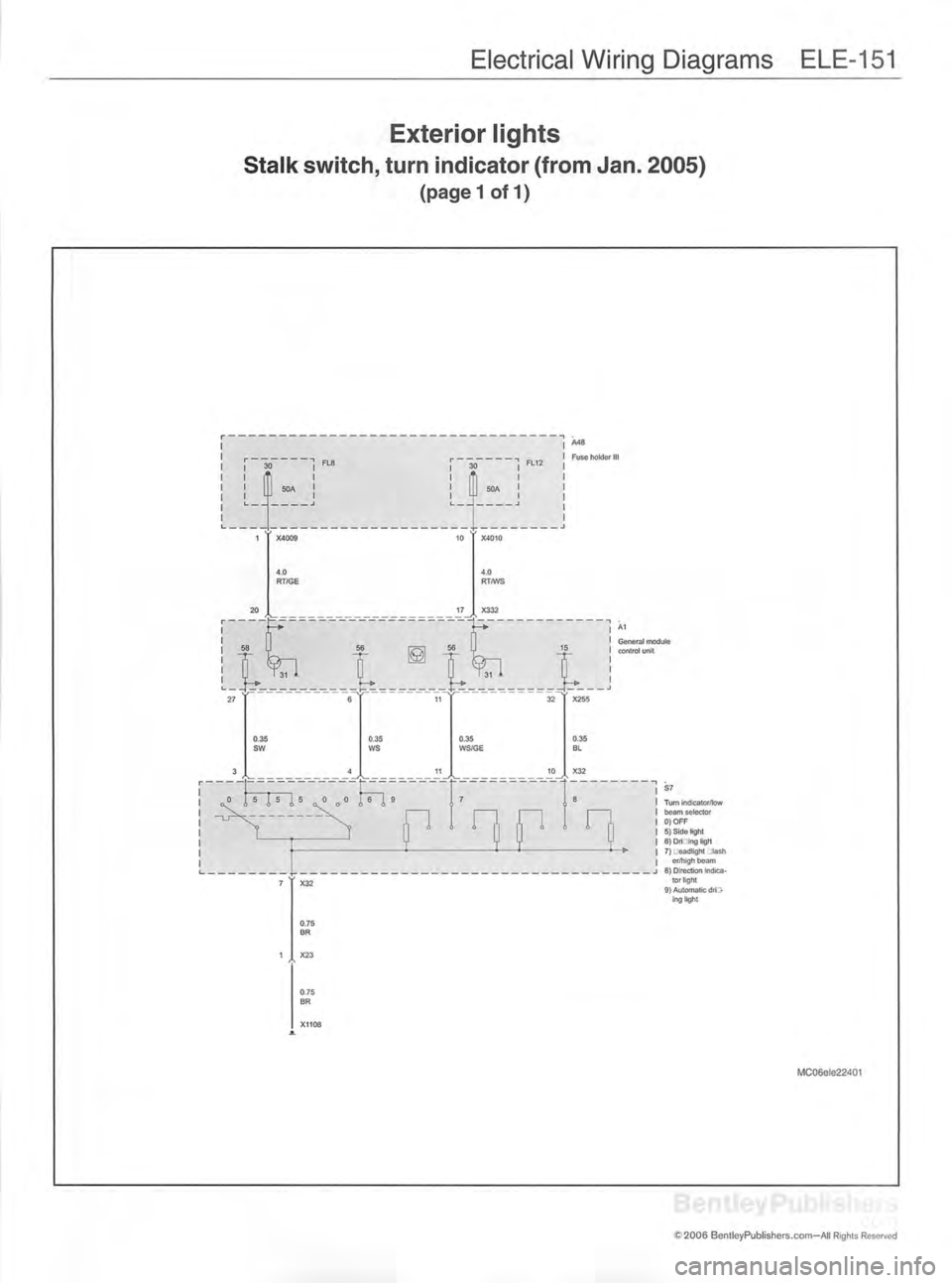
Electrical Wiring Diagrams ELE-151
Exterior lights
Stalk switch, turn indicator (from Jan. 2005)
(pagel of 1)
A48
Fuse holder II
General module
control unitS7
Turn indicator/lowbeam selector
0)OFF 5) Side light
6) Dri -ing light
7) jeadlight :tash er/high beam
8) Direction Indica tor light
9} Automatic dri;> ing light
MC06ele22401
C S f c ■■ !
'£ 2006 BentleyPublishers.com-AII Rights Reserved
Page 980 of 1079

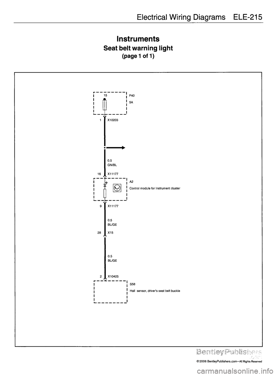
Electrical Wiring Diagrams ELE-215
Instruments
Seat belt warning light
(pagel of 1)
F40
I 1 5
| i L
5A
i_ _ —r
1X10203
<
0.5
GN/BL
16
iX11177
s
'•A21 1
!mControl module for instrument cluster
i LJ
9 X11177
0.5
B17GE
28
tX15
0.5
BL/GE
2
ir — — ■X10425
s
S58
Hall sensor, driver's seat belt buckle
•;. p^r'.pr >,?? ■&£ ;. 'r'v'"< ; '
©2006 BentleyPublishers.com—All Rights Reserved