lock MINI COOPER 2002 Service Repair Manual
[x] Cancel search | Manufacturer: MINI, Model Year: 2002, Model line: COOPER, Model: MINI COOPER 2002Pages: 1079, PDF Size: 70.32 MB
Page 418 of 1079

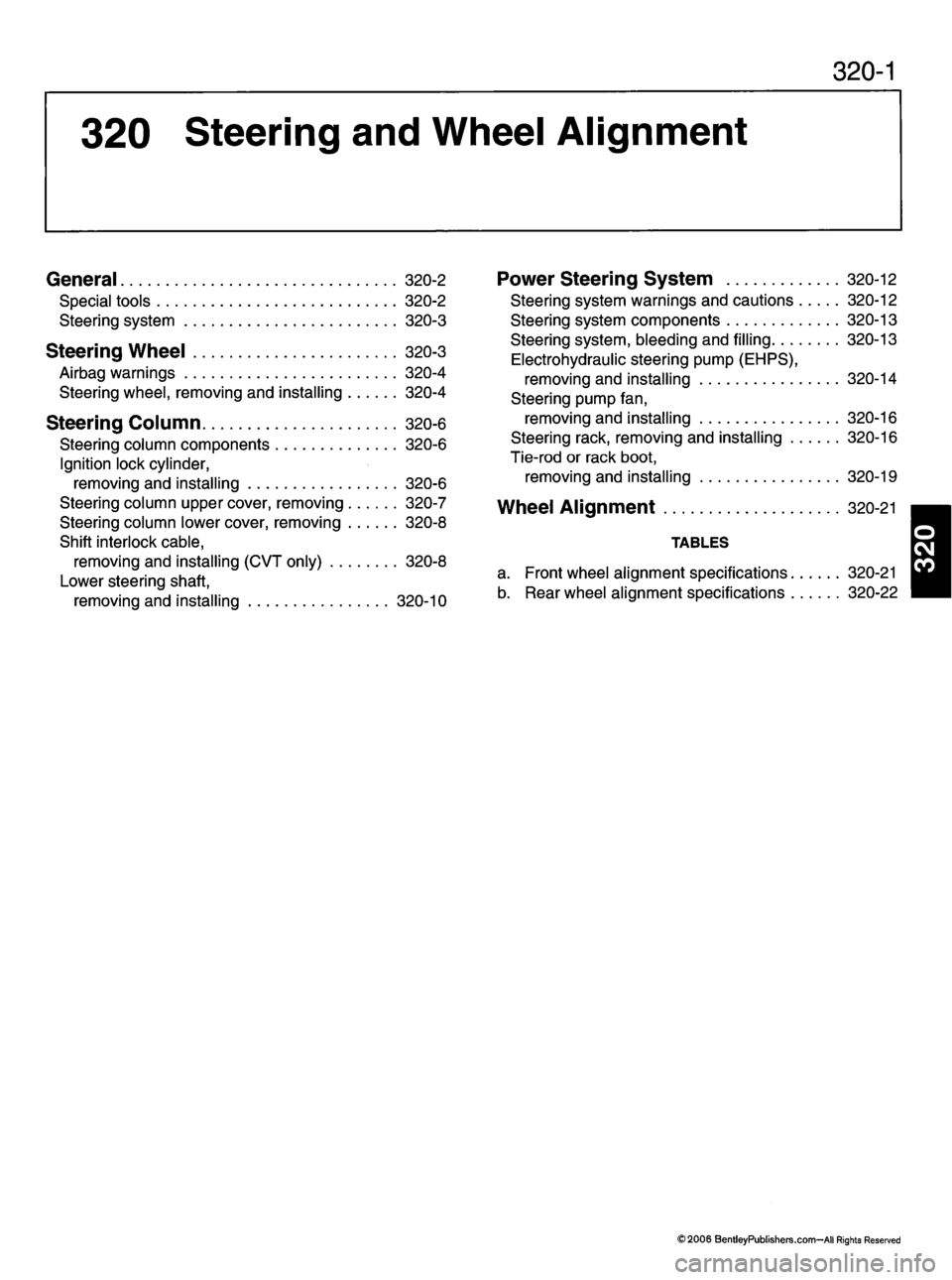
320-1
320 Steering and Wheel Alignment
General 320-2
S p e c i a l t o o l s 3 2 0 - 2
S t e e r i n g s y s t e m 3 2 0 - 3
Steering Wheel 320-3
A i r b a g w a r n i n g s 3 2 0 - 4 Steering wheel, removing and installing 320-4
Steering Column 320-6
S t e e r i n g c o l u m n c o m p o n e n t s 3 2 0 - 6
Ignition lock cylinder, removing and installing 320-6
Steering column upper cover, removing 320-7
Steering column lower cover, removing 320-8
Shift interlock cable,
r e m o v i n g a n d i n s t a l l i n g ( C V T o n l y ) 3 2 0 - 8
Lower steering shaft,
removing and installing 320-10
P o w e r S t e e r i n g S y s t e m 3 2 0 - 1 2
Steering system warnings and cautions 320-12
S t e e r i n g s y s t e m c o m p o n e n t s 3 2 0 - 1 3
Steering system, bleeding and filling 320-13Electrohydraulic steering pump (EHPS), removing and installing 320-14
Steering pump fan, removing and installing 320-16
Steering rack, removing and installing 320-16
Tie-rod or rack boot,
removing and installing 320-19
Wheel Alignment 320-21
TA B L E S
a. Front wheel alignment specifications 320-21
b. Rear wheel alignment specifications 320-22
1
©2006 BentleyPublishers.com-AII Rights Reserved
Page 521 of 1079

Rear Hatch 412-9
Rear Lid (Convertible)
CI
FaJW&\
; Ib :(bj
3pfe:
min412017 I
<
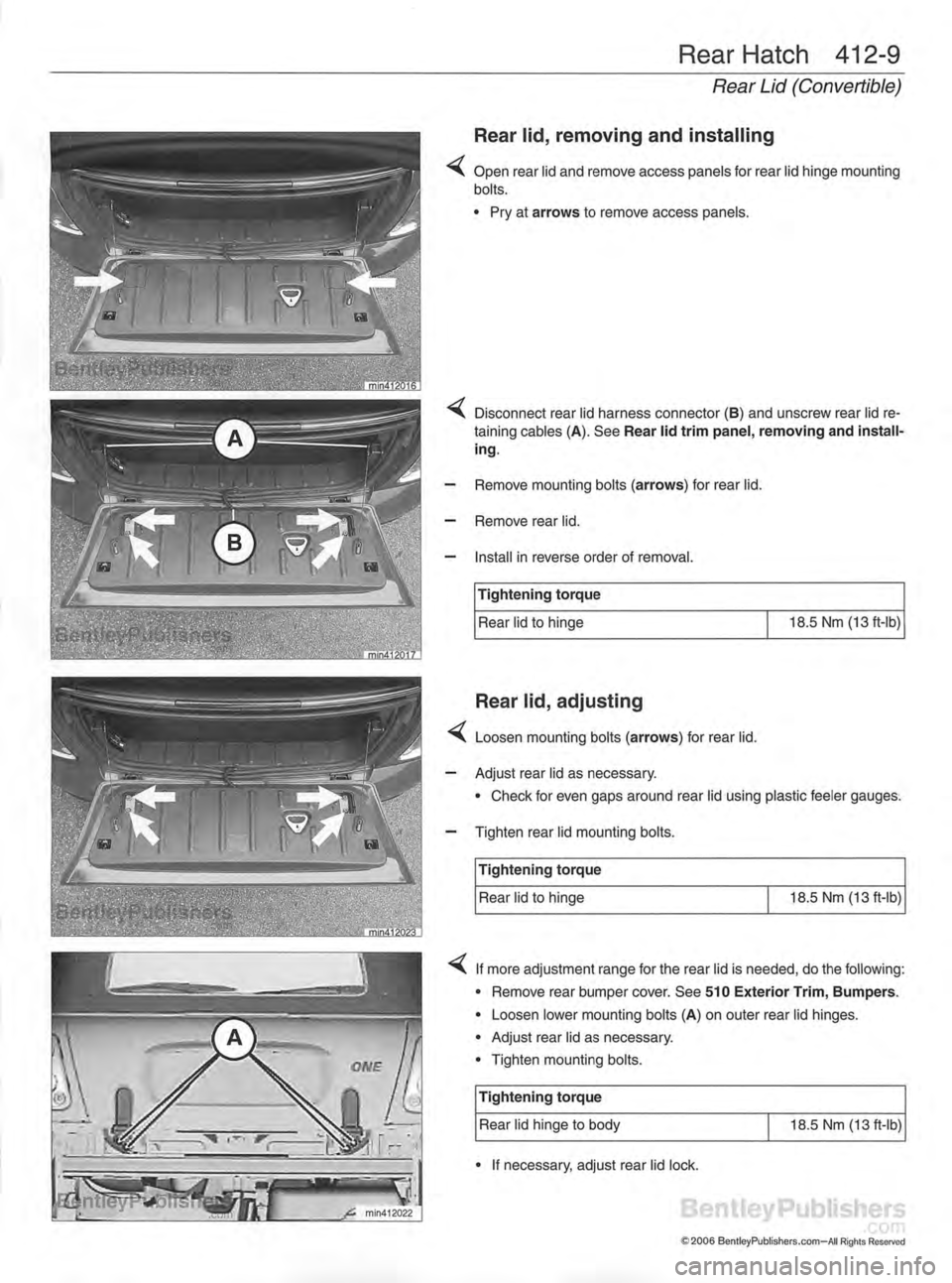
Rear lid, removing and installing
Open rear lid and remove access panels for rear lid hinge mounting
bolts.
• Pry at arrows to remove access panels.
"^C Disconnect rear lid harness connector (B) and unscrew rear lid re taining cables (A). See Rear lid trim panel, removing and installing.
— Remove mounting bolts (arrows) for rear lid.
— Remove rear lid.
— Install in reverse order of removal.
Tightening torqueRear lid to hinge 18.5Nm(13ft-lb)
Rear lid, adjusting
^ Loosen mounting bolts (arrows) for rear lid.
— Adjust rear lid as necessary. • Check for even gaps around rear lid using plastic feeler gauges.
— Tighten rear lid mounting bolts.
Tightening torque
Rear lid to hinge 18.5Nm(13ft-lb)
^K. If more adjustment range for the rear lid is needed, do the following: • Remove rear bumper cover. See 510 Exterior Trim, Bumpers.
• Loosen lower mounting bolts (A) on outer rear lid hinges.
• Adjust rear lid as necessary.
• Tighten mounting bolts.
Tightening torqueRear lid hinge to body 18.5 Nm(13ft-lb)
• If necessary, adjust rear lid lock.
S2006 BentleyPublishers.com—All Rights Reserved
Page 562 of 1079

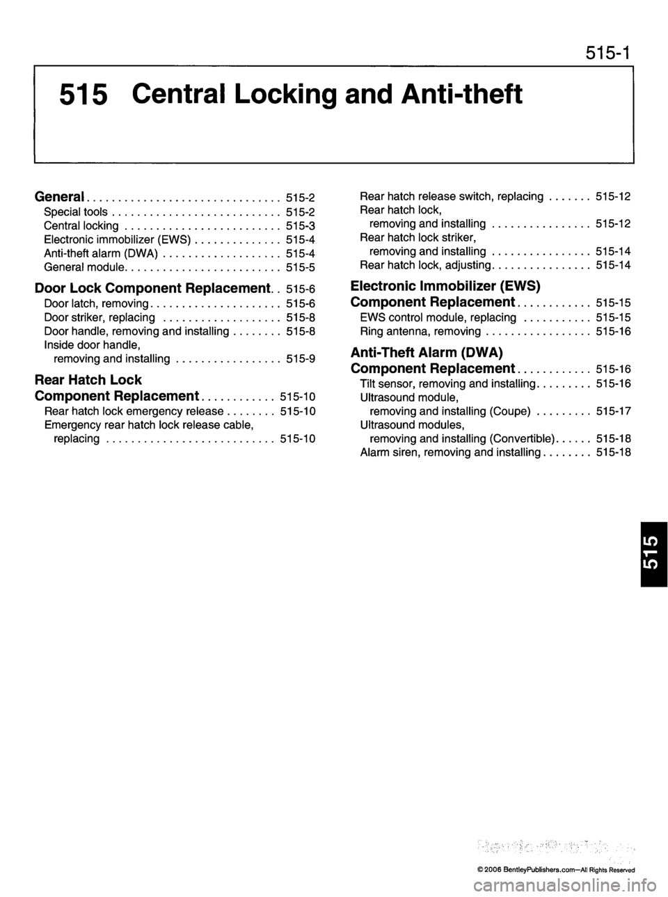
515 Central Locking and Anti-theft
515-1
General 515-2
S p e c i a l t o o l s 5 1 5 - 2
Central locking 515-3
E l e c t r o n i c i m m o b i l i z e r ( E W S ) 5 1 5 - 4
A n t i - t h e f t a l a r m ( D W A ) 5 1 5 - 4
General module 515-5
Door Lock Component Replacement.. 515-6
D o o r l a t c h , r e m o v i n g 5 1 5 - 6
D o o r s t r i k e r , r e p l a c i n g 5 1 5 - 8
Door handle, removing and installing 515-8
Inside door handle,
removing and installing 515-9
Rear Hatch Lock
Component Replacement 515-10
Rear hatch lock emergency release 515-10
Emergency rear hatch lock release cable,replacing 515-10Rear hatch release switch, replacing 515-12
Rear hatch lock,
removing and installing 515-12
Rear hatch lock striker,
removing and installing 515-14
R e a r h a t c h l o c k , a d j u s t i n g 5 1 5 - 1 4
Electronic Immobilizer (EWS)
Component Replacement 515-15
E W S c o n t r o l m o d u l e , r e p l a c i n g 5 1 5 - 1 5
Ring antenna, removing 515-16
Anti-Theft Alarm (DWA)
Component Replacement 515-16
Tilt sensor, removing and installing 515-16
Ultrasound module,
removing and installing (Coupe) 515-17
Ultrasound modules,
removing and installing (Convertible) 515-18
Alarm siren, removing and installing 515-18
1
©2006 BentleyPublishers.com—All Rights Reserved
Page 654 of 1079

620 Instruments
620-1
General 620-2
I n s t r u m e n t C l u s t e r a n d C a r r i e r 6 2 0 - 2
Instrument cluster, removing and installing 620-2
Instrument carrier,
removing and installing 620-3 Navigation system carrier,
removing and installing 620-3
C l o c k 6 2 0 - 4
Roof mounted clock,
removing and installing 620-4
©2006 BentleyPublishers.com—All Rights Reserved
Page 766 of 1079

ELE-1
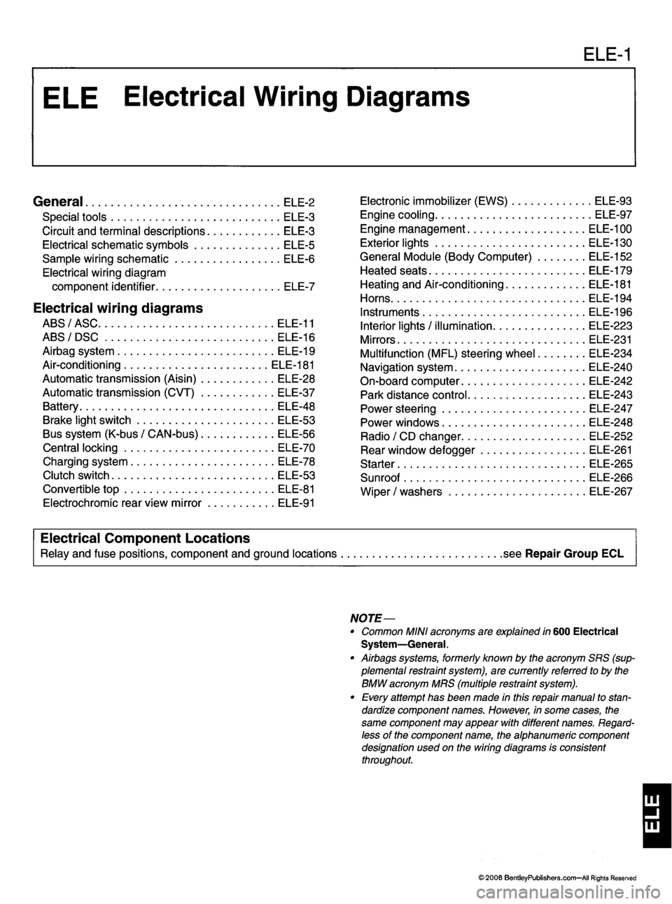
General ele-2
S p e c i a l t o o l s E L E - 3
C i r c u i t a n d t e r m i n a l d e s c r i p t i o n s E L E - 3
E l e c t r i c a l s c h e m a t i c s y m b o l s E L E - 5
S a m p l e w i r i n g s c h e m a t i c E L E - 6
Electrical wiring diagram
c o m p o n e n t i d e n t i fi e r E L E - 7
Electrical wiring diagrams
ABS/ASC ELE-11
A B S / D S C E L E - 1 6
A i r b a g s y s t e m E L E - 1 9
Air-conditioning ELE-181
A u t o m a t i c t r a n s m i s s i o n ( A i s i n ) E L E - 2 8
A u t o m a t i c t r a n s m i s s i o n ( C V T ) E L E - 3 7
B a t t e r y E L E - 4 8
Brake light switch ELE-53
B u s s y s t e m ( K - b u s / C A N - b u s ) E L E - 5 6
Central locking ELE-70
C h a r g i n g s y s t e m E L E - 7 8
Clutch switch ELE-53
Convertible top ELE-81 E l e c t r o c h r o m i c r e a r v i e w m i r r o r E L E - 9 1 E l e c t r o n i c i m m o b i l i z e r ( E W S ) E L E - 9 3
Engine cooling ELE-97
Engine management ELE-100
E x t e r i o r l i g h t s E L E - 1 3 0
G e n e r a l M o d u l e ( B o d y C o m p u t e r ) E L E - 1 5 2
H e a t e d s e a t s E L E - 1 7 9
Heating and Air-conditioning ELE-181
H o r n s
E L E - 1 9 4
I n s t r u m e n t s E L E - 1 9 6
I n t e r i o r l i g h t s / i l l u m i n a t i o n E L E - 2 2 3
M i r r o r s E L E - 2 3 1
M u l t i f u n c t i o n ( M F L ) s t e e r i n g w h e e l E L E - 2 3 4
N a v i g a t i o n s y s t e m E L E - 2 4 0
O n - b o a r d c o m p u t e r E L E - 2 4 2
P a r k d i s t a n c e c o n t r o l E L E - 2 4 3
P o w e r s t e e r i n g E L E - 2 4 7
P o w e r w i n d o w s E L E - 2 4 8 R a d i o / C D c h a n g e r E L E - 2 5 2
R e a r w i n d o w d e f o g g e r E L E - 2 6 1
S t a r t e r E L E - 2 6 5
Sunroof ELE-266
W i p e r / w a s h e r s E L E - 2 6 7
Electrical Component Locations
Relay and fuse positions, component and ground locations .see Repair Group ECL
NOTE—
• Common MINI acronyms are explained in 600 Electrical System—General.
• Airbags systems, formerly known by the acronym SRS (sup
plemental restraint system), are currently referred to by the
BMW acronym MRS (multiple restraint system).
• Every attempt has been made in this repair manual to stan
dardize component names. However, in some cases, the
same component may appear with different names. Regard
less of the component name, the alphanumeric component
designation used on the wiring diagrams is consistentthroughout.
1
©2006 BentleyPublishers.com—All Rights Reserved