ECO mode MINI COOPER 2003 Owners Manual
[x] Cancel search | Manufacturer: MINI, Model Year: 2003, Model line: COOPER, Model: MINI COOPER 2003Pages: 148, PDF Size: 3.17 MB
Page 10 of 148

8
NOTES
Installation and operation of non-MINI
approved accessories such as alarms,
radios, amplifiers, radar detectors, wheels,
suspension components, brake dust
shields, telephones – including operation of
any portable cellular phone from within
the vehicle without using an externally
mounted antenna – or transceiver equip-
ment – e.g. CB, walkie-talkie, ham radio or
similar – may cause extensive damage to
the vehicle, compromise its safety, inter-
fere with the vehicle's electrical system or
affect the validity of the MINI Limited
Warranty. See your MINI Dealer for addi-
tional information.
<
Maintenance, replacement, or repair
of the emission control devices and
systems may be performed by any auto-
motive repair establishment or individual
using any certified automotive part.
<
Symbol on vehicle parts
Indicates that you should consult the
relevant section of this Owner's Man-
ual for information on a particular part or
assembly.
Service and warranty
This manual is supplemented by a Service
and Warranty Information Booklet for US
models or a Warranty and Service Guide
Booklet for Canadian models.
We recommend that you read this publica-
tion thoroughly.
Your MINI is covered by the following
warranties:
>
New Vehicle Limited Warranty
>
Rust Perforation Limited Warranty
>
Federal Emissions System Defect
Warranty
>
Federal Emissions Performance
Warranty
>
California Emission Control System Lim-
ited Warranty
Detailed information about these warran-
ties is listed in the Service and Warranty
Information Booklet for US models or in the
Warranty and Service Guide Booklet for
Canadian models.
Reporting safety defects
The following only applies to vehicles
owned and operated in the US.
If you believe that your vehicle has a defect
which could cause a crash or could cause
injury or death, you should immediately
inform the National Highway Traffic Safety
Administration NHTSA in addition to
notifying the MINI Division of BMW of
North America, LLC, P.O. Box 1227, West-
wood, New Jersey 07675-1227,
Telephone toll-free 1-866-275-6464.
If NHTSA receives similar complaints, it
may open an investigation, and if it finds
that a safety defect exists in a group of
vehicles, it may order a recall and remedy
campaign. However, NHTSA cannot
become involved in individual problems
between you, your dealer, or BMW of North
America, LLC.
To contact NHTSA, you may either
call the Auto Safety Hotline toll-free
at 1-800-424-9393 or 366-0123 in
Washington, D.C. area, or write to:
NHTSA, U.S. Department of Transportation,
Washington, D.C. 20590. You can also
obtain other information about motor
vehicle safety from the Hotline.
ba.book Seite 8 Montag, 5. August 2002 8:09 20
ProCarManuals.com
Page 18 of 148

16
INDICATOR AND WARNING LAMPS
Yellow: stop immediately
Flat Tire Monitor
●
Flashes: tire failure.
Reduce speed immediately and
stop the vehicle.
With Run Flat tires:
Carefully reduce the driving speed to below
50 mph / 80 km/h and continue to a safe
location.
In both cases, avoid hard brake applications
and steering maneuvers. Check the tire
inflation pressures.
Conduct in the event of a flat tire, refer to
pages 112, 116.
General information on the system, refer to
page 64
Red and yellow: continue driving
cautiously
Brake warning lamp together with
the gold indicator lamp for ABS,
EBD and ASC+T/DSC:
The control system ABS, EBD and
ASC+T/DSC has failed. Drive cau-
tiously and defensively. Avoid full
brake applications. Please have the
system checked by your MINI
Dealer as soon as possible.
More information on pages 62, 63
Brake warning lamp together with
the yellow indicator warning lamps
ABS, EBD and ASC+T/DSC for
Canadian models.
Red: an important reminder
Brake warning lamp
with parking brake applied.
More information on the parking
brake on page 47
Brake warning lamp for Canadian
models.
Fasten safety belts
●
Lights up for several seconds or,
depending on the version, until
after the safety belts are fastened. A sig-
nal
*
also sounds depending on the version.
More information on page 38
Depending on the level of equipment,
the indicator lamp is in the vicinity of
the navigation system.
<
Airbags
●
Please have the system inspected
at your MINI Dealer.
More information on pages 33, 40
Depending on the level of equipment,
the indicator lamp is in the vicinity of
the navigation system.
<
Bonnet/Tailgate
Lights up when the bonnet and/or
tailgate are open.
More information on pages 27, 91
ba.book Seite 16 Montag, 5. August 2002 8:09 20
ProCarManuals.com
Page 30 of 148

28
ELECTRIC POWER WINDOWSTo open and close windowsFrom ignition key position 1:
To open:
Press the switch downwards.
The window opens until you release the
switch
or
briefly press the switch downwards.
The window opens automatically.
Pressing the switch again stops the opera-
tion.
To close:
Press the switch upwards.
The window closes until you release the
switch.
The window on the front passenger
side cannot be closed automati-
cally.<
Watch during the closing process to
be sure that no one is injured.<
After the ignition has been switched off:
You can use the electric power windows as
long as no one opens any of the doors.
If a door is opened during operation, the
opening/closing process stops immedi-
ately.
When leaving the vehicle, always
remove the ignition key from the lock
and remember to close the doors, e.g. to
prevent children from operating the power
windows and injuring themselves.<
For the convenience mode via the door
lock, refer to page 25.
To initialize power windows
If the battery is disconnected, e.g. for
changing batteries or vehicle storage,
re-initialize the power windows. Other-
wise the windows will not be lowered
when the door is opened.<
1. Close the doors
2. Close both windows
3. Hold both switches of the power win-
dows up for approx. one second.
In the event of a system malfunction,
please contact your MINI Dealer.<
ba.book Seite 28 Montag, 5. August 2002 8:09 20
ProCarManuals.com
Page 48 of 148

46
STARTING THE ENGINE Do not allow the engine to warm up with
the vehicle at a standstill. Move off imme-
diately at a moderate engine speed.
Do not allow the engine to run in
enclosed spaces. The exhaust gases
contain carbon monoxide, an odorless and
colorless, but highly toxic gas. Breathing
the exhaust gases poses an extreme health
risk, and can lead to unconsciousness and
death.
Do not leave the vehicle unattended with
the engine running. This is a safety hazard.
When driving, standing at idle or parking
the vehicle, take care to avoid contact
between the hot exhaust system and flam-
mable materials – e.g. hay, leaves, grass,
etc. Such contact could lead to a fire, result-
ing in serious personal injury and property
damage.<
StartingWhen starting the engine, do not press the
accelerator pedal.
Do not actuate the starter for too
short a time. Do not turn it for more
than approx. 20 seconds. Release the igni-
tion key immediately when the engine
starts.
Extended starting attempts, characterized
by excessively frequent or long periods
with the starter engaged, can lead to dam-
age in the catalytic converter.<
If the engine does not start on the first
attempt, for instance if the engine is very
hot or cold:
>When starting the engine, press the gas
pedal down halfway.
When first starting the engine at very low
temperatures – from +5 7 / –15 6:
>When starting the engine, press the gas
pedal down halfway
>For the initial start attempt, allow the
starter to remain engaged somewhat
longer, approx. 10 seconds.
Manual transmission1. Engage the parking brake
2. Put the manual gearshift lever in neutral
3. Press the clutch pedal
4. Start the engine.Continuously Variable automatic
Transmission (CVT)*1. Press the footbrake
2. Put the selector lever in position P or N
3. Start the engine.
Move the selector lever to position P
and engage the parking brake before
leaving your vehicle with the engine run-
ning.
Do not leave the vehicle unattended with
the engine running. This is a safety haz-
ard.<
ba.book Seite 46 Montag, 5. August 2002 8:09 20
ProCarManuals.com
Page 62 of 148

60
SERVICE INTERVAL DISPLAY CLOCK COMPUTER
*
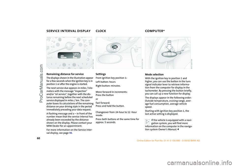
Remaining distance for service
The displays shown in the illustration appear
for a few seconds when the ignition key is in
position 1 or after the engine is started.
The next service due appears in miles / kilo-
meters with the message "inspection"
and/or "oil service", together with the dis-
tance remaining before the next scheduled
service displayed in miles / km. The com-
puter bases its calculations of the remaining
distance on your driving style in the period
immediately preceding your data request.
A flashing message and a – in front of the
number mean that the service interval has
already been exceeded by the distance
shown on the display. Please contact your
MINI Dealer for an appointment.
For more information on the Service inter-
val display, see page 98.
SettingsFrom ignition key position 1:
Left button: hours
Right button: minutes.
Move forward in increments:
Press the button
or
fast forward:
Press and hold the button.
Changeover from 24-hour to 12 -hour
mode:
Press both buttons at the same time for
approx. 5 seconds.
Mode selectionWith the ignition key in position 1 and
higher, you can use the button in the turn
signal indicator lever to retrieve informa-
tion from the computer for display in the
tachometer. By pressing the button briefly,
you can call up a new function for display.
The displays appear in the following order:
Outside temperature, cruising range, aver-
age fuel consumption, average vehicle
speed.
Starting with ignition key position 1, the
last active setting is displayed.
If the vehicle is equipped with a navi-
gation system, you will find more
information on the computer in the naviga-
tion system Owner‘s Manual.<
ba.book Seite 60 Montag, 5. August 2002 8:09 20
ProCarManuals.com
Page 84 of 148

82
REFUELING
Always switch off the engine before
refueling. If you do not, fuel cannot
be filled into the tank and the "Service
Engine Soon" lamp may come on.<
1. Open the fuel filler door
2. Turn the filler cap counterclockwise
3. Put the filler cap in the bracket attached
to the fuel filler door.
Always observe all applicable precau-
tions and regulations when handling
fuels. Never carry spare fuel containers in
your vehicle. Whether empty or full, these
containers can leak, cause an explosion,
and lead to fire in the event of a collision.<
Simple and environmentally friendly
Always observe all safety precautions
posted at the service station when
handling fuel.<
When refueling, insert the filler nozzle
completely into the filler pipe. Pulling the
nozzle out of the pipe during refueling
>results in premature pump shutoff
>will reduce the effect of the fuel vapor
recovery system on the pump.
As long as the filler nozzle is used properly,
the fuel tank is full whenever the nozzle
shuts off the first time.
Close tank:
1. Put on filler cap
2. Turn filler cap clockwise until it clicks
3. Close fuel filler door.
Fuel tank capacity:
approx. 13.2 gallons / 50 liters, of which
approx. 2.1 gallons / 8 liters are reserve
capacity.
Close the filler cap carefully after
refueling until a click is heard.
While closing, be sure not to squeeze the
strap which is fastened to the filler cap.
US models only:
A loose or missing cap will activate the
message CHECK FILLER CAP in the Check
Control* or the Check Filler Cap lamp
*.<
Do not drive until the fuel tank is
totally empty, otherwise engine oper-
ations are not guaranteed and damage
could occur.<
ba.book Seite 82 Montag, 5. August 2002 8:09 20
ProCarManuals.com
Page 86 of 148

84
BRAKE SYSTEMBrake fluid level If the brake fluid level is too low and brake
pedal travel has become longer, there may
be a defect in one of the brake system's
hydraulic circuits.
Proceed to the nearest MINI Dealer.
Higher brake application pressure
may be necessary under these conditions,
there may be a slight pull to one side, and
brake pedal travel may be longer. Please
remember to adapt your driving style
accordingly.<
Disc brakesWhen the vehicle is driven only occasion-
ally, during extended periods when the
vehicle is not used at all, and in operating
conditions where brake applications are
less frequent, there is an increased ten-
dency for corrosion of the brake rotors and
accumulation of contamination on the
brake pads. This occurs because the mini-
mal pressure that must be exerted by the
pads to clean the rotors by brake applica-
tions is not reached.
Corrosion on brake rotors is signaled by a
running or pulsation during braking; even
extended subsequent braking will not cure
this phenomenon.
It is a good idea to periodically dry the
brakes with a gentle application when driv-
ing in rain and on wet roads. Monitor traffic
conditions to ensure that this maneuver
does not endanger other road users. The
resulting heat dries the brake rotor and the
brake pads. Then if braking effect is
needed, it is immediately available.
Extended or steep mountain descents
should be driven in the gear or in the driv-
ing position in which only minimal periodic
brake application is required. This helps
avoid placing excessive loads on the brake system. Stay within the allowable speed
range, refer to page 58.
Do not coast with the clutch pressed
or with the transmission or selector
lever in Neutral. Do not coast with the
engine switched off. The engine provides
no braking effect when the transmission is
in Neutral, and there is no power-assist for
braking when the engine is switched off.<
Brake pads
For your own safety: use brake pads
which the manufacturer of your MINI
has approved for your particular vehicle
model. The manufacturer of your MINI can-
not evaluate non-approved brake pads to
determine if they are suitable for use, and
therefore cannot ensure the operating
safety of the vehicle in the event of their
use.<
ba.book Seite 84 Montag, 5. August 2002 8:09 20
ProCarManuals.com
Page 88 of 148

86
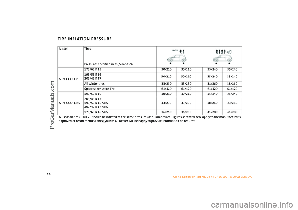
TIRE INFLATION PRESSUREModel Tires
Pressures specified in psi/kilopascal
MINI COOPER175/65 R 15 30/210 30/210 35/240 35/240
195/55 R 16
205/45 R 1730/210 30/210 35/240 35/240
All winter tires 33/230 33/230 38/260 38/260
Space-saver spare tire 61/420 61/420 61/420 61/420
MINI COOPER S195/55 R 16 30/210 30/210 35/240 35/240
205/45 R 17
195/55 R 16 M+S
205/45 R 17 M+S33/230 33/230 38/260 38/260
175/60 R 16 M+S 36/250 36/250 41/280 41/280
All-season tires – M+S – should be inflated to the same pressures as summer tires. Figures as stated here apply to the manufacturer’s
approved or recommended tires; your MINI Dealer will be happy to provide information on request.
ba.book Seite 86 Montag, 5. August 2002 8:09 20
ProCarManuals.com
Page 91 of 148

89
OVERVIEW REPAIRSOPERATIONCONTROLS DATA INDEX
WHEEL AND TIRE COMBINATIONS WINTER TIRESThe right choiceThe factory-approved normal and Run Flat
tires are matched to your vehicle and have
been selected to provide optimum safety
and driving comfort if used properly.
The manufacturer of your MINI rec-
ommends never mounting wheels
and tires that have not been specifically
approved by the manufacturer for use on
your particular model. Although other
wheels and tires may theoretically have the
same dimensions, variations in factors such
as manufacturing tolerances can result in
contact between tire and bodywork, ulti-
mately leading to serious accidents. The
manufacturer of your MINI cannot evaluate
non-approved wheels and tires to deter-
mine if they are suited for use, and there-
fore cannot ensure the operating safety of
the vehicle if they are fitted.<
The manufacturer of your MINI has tested
certain tire brands in each size, categorized
them as safe for use on the road, and
approved them. Contact your MINI Dealer
for more details.
The correct wheel and tire combina-
tion affects various systems that
would otherwise be impaired, e.g. ABS,
ASC+T and DSC. For this reason, use only
tires of the same manufacture and tread
configuration. In the event of a flat tire, for
example, remount the approved wheel and
tire combination as soon as possible.<
StorageStore tires in a cool, dry place, protecting
them against light whenever possible.
Protect the tires against contact with oil,
grease and fuel.
Choosing the right tireThe manufacturer of your MINI recom-
mends winter tires – M+S radial tires – for
driving in adverse winter road conditions.
While so-called all-season tires with M+S
designation provide better winter traction
than summer tires with the load ratings S,
T, H, V, W, they do not achieve the perfor-
mance of winter tires.
In the interest of safe tracking and steering
response, install winter tires made by the
same manufacturer having the same tread
configuration on all four wheels.
Before purchasing winter tires, check
whether your MINI is fitted with Run Flat
tires. You will recognize Run Flat tires by a
circular symbol containing the letters RSC
on the side of the tire, see page 116. In this
case, use only Run Flat tires, as in the event
of a flat tire there is no space-saver spare
tire.
Any MINI Dealer will be glad to advise you
on the selection of the right winter tires for
the relevant operating conditions.
ba.book Seite 89 Montag, 5. August 2002 8:09 20
ProCarManuals.com
Page 142 of 148

EVERYTHING FROM A TO Z
140
turn signal indicators108
xenon lamps107
Lashing eyes75
LATCH
child seat fastening
system43
identification43
Leather care101
LED light-emitting diodes54
Length131
License plate lamp
bulb replacement110
Lifting handle, space-saver
spare tire112
Light-alloy wheels100
Lighting
cargo area lamps53
"Lights on" warning52
Liquid sealant
filling119
Load securing devices75
Loading75
Loading cargo75
Low beams52,107
Lug bolts114
Luggage compartment
see Cargo area
Luggage compartment cover,
see Cargo area cover74
Luggage compartment lamps,
see Cargo area lamps111 Luggage rack,
see Roof-mounted luggage
rack76
Lumbar support35
M
M+S tires89
Maintenance60,98
Maintenance System98
Manual operation
driver's door25
sliding/tilt sunroof30
tailgate27
Manual transmission48
Manufacturer6
Master key
initialization22
with remote control22
Mechanical key22
MINI Maintenance System98
MINI manufacturer6
MINI Mobility System
compressor120
liquid sealant119
on-board tools118
Mirror heater39
Mirrors39
Modifications, technical103
Multifunction steering
wheel19
Multifunction switch52 N
Navigation system, see
separate Owner's
Manual14
Non-smoker's equipment
package, see Cigarette lighter
socket73
Nozzles69,72
Nylon rope126
O
OBD interface socket102
Odometer58
Oil94
additives95
consumption94
dipstick94
High Performance Synthetic
Oil96
level15
pressure15
recommended grades of
oil95
viscosities96
Oil change intervals, see Service
and Warranty Booklet for US
models, or Warranty and
Service Guide Booklet for
Canadian models
Oil service60
Old batteries122 On-board tool kit106
On-board tools112,118
Opening
from inside26
from outside23
Outside temperature
display61
P
Park Distance Control
(PDC)66
Parking brake16,47
Parking lamps52
bulb replacement108
Parking lamps/Low beams52
Parking vehicle81
Particle filter69,72
PDC (Park Distance
Control)66
Phillips screwdriver118
Plastic100
Pollen69,72
Power output17,130
Power supply 12 V73
Power windows
electric power windows28
initialize28
Pressure, tires85,115,120
Pushing/Towing126
ba.book Seite 140 Montag, 5. August 2002 8:09 20
ProCarManuals.com