check engine MINI COOPER 2004 Owners Manual
[x] Cancel search | Manufacturer: MINI, Model Year: 2004, Model line: COOPER, Model: MINI COOPER 2004Pages: 152, PDF Size: 1.53 MB
Page 17 of 152

15
OVERVIEW REPAIRS OPERATION CONTROLS DATA INDEX
INDICATOR AND WARNING LAMPS
Technology that monitors itself
The system runs a check on the indicator
and warning lamps marked by
+
each time
you switch on the ignition. They each light
up once for different periods of time.
If a malfunction should occur in one of
these systems, the corresponding lamp
does not go out after the engine is started
or it lights up while the vehicle is moving.
You will see below the correct way to react
to this.
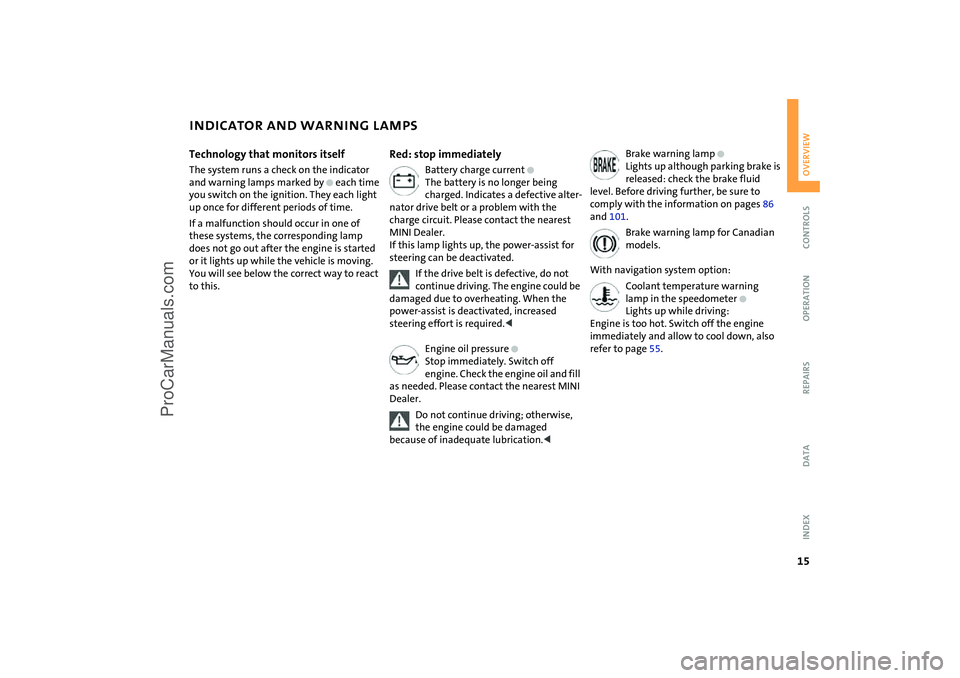
Red: stop immediately
Battery charge current
+
The battery is no longer being
charged. Indicates a defective alter-
nator drive belt or a problem with the
charge circuit. Please contact the nearest
MINI Dealer.
If this lamp lights up, the power-assist for
steering can be deactivated.
If the drive belt is defective, do not
continue driving. The engine could be
damaged due to overheating. When the
power-assist is deactivated, increased
steering effort is required.
<
Engine oil pressure
+
Stop immediately. Switch off
engine. Check the engine oil and fill
as needed. Please contact the nearest MINI
Dealer.
Do not continue driving; otherwise,
the engine could be damaged
because of inadequate lubrication.
<
Brake warning lamp
+
Lights up although parking brake is
released: check the brake fluid
level. Before driving further, be sure to
comply with the information on pages 86
and 101.
Brake warning lamp for Canadian
models.
With navigation system option:
Coolant temperature warning
lamp in the speedometer
+
Lights up while driving:
Engine is too hot. Switch off the engine
immediately and allow to cool down, also
refer to page 55.
ProCarManuals.com
Page 19 of 152

17
OVERVIEW REPAIRS OPERATION CONTROLS DATA INDEX
INDICATOR AND WARNING LAMPS
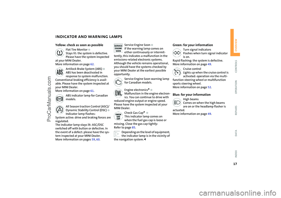
Yellow: check as soon as possible
Flat Tire Monitor
+
Stays lit: the system is defective.
Please have the system inspected
at your MINI Dealer.
More information on page 62.
Antilock Brake System (ABS)
+
ABS has been deactivated in
response to system malfunction.
Conventional braking efficiency is avail-
able. Please have the system inspected at
your MINI Dealer.
More information on page 61.
ABS indicator lamp for Canadian
models.
All Season traction Control (ASC)/
Dynamic Stability Control (DSC)
+
Indicator lamp flashes:
System active: drive and braking forces are
regulated.
The indicator lamp stays lit: ASC/DSC
switched off with button or defective. In
the event of a defect: please have the sys-
tem inspected at your MINI Dealer.
More information on pages 59, 60.
Service Engine Soon
+
If the warning lamp comes on
either continuously or intermit-
tently, this indicates a malfunction in the
emissions-related electronic systems.
Although the vehicle remains operational,
you should have the systems checked by
your MINI Dealer at the earliest possible
opportunity.
Service Engine Soon warning lamp
for Canadian models.
Engine electronics
*
+
Malfunction in the engine electron-
ics. You can continue to drive with
reduced engine output or engine speed.
Please have the system inspected at your
MINI Dealer.
Check Gas Cap
*
+
This indicator lamp comes on
when the fuel gas cap is loose or
missing. Close the gas cap tightly:
Refer to page 85.
Depending on the level of equipment,
the indicator lamp is in the vicinity of
the navigation system.
<
Green: for your information
Turn signal indicators
Flashes when turn signal indicator
is on.
Rapid flashing: the system is defective.
More information on page 49.
Cruise control
Lights up when the cruise control is
activated: operation via the multi-
function steering wheel or multifunction
sports steering wheel.
More information on page 52.
Blue: for your information
High beams
Comes on when the high beams
are on or the headlamp flasher is
actuated.
More information on page 49.
ProCarManuals.com
Page 57 of 152

55
OVERVIEW REPAIRS OPERATIONCONTROLS DATA INDEX
FUEL GAUGE COOLANT TEMPERATURE GAUGEIn the navigation system
Please also comply with the instruc-
tions in the previous section.<
If the indicator light 1 changes from orange
to red, there are approx. 2.1 gallons /
8 liters of fuel in the tank.
Low temperature The needle is at the bottom or on the right
of the range.
The engine is still cold. Drive at moderate
engine and vehicle speeds.Center positionNormal operating temperature of the
engine.High temperatureAs soon as there is a deviation from the
center position upwards or to the left:
Drive moderately and at low engine speed.
If necessary, switch off the engine and
allow it to cool down.
Checking coolant level, refer to page 100.
1Red indicator lampWhen you switch on the ignition, warning
lamp 1 comes on briefly to confirm that the
system is operational.
Lights up while driving:
Engine is too hot. Switch off the engine
immediately and allow it to cool down.Navigation system option
Coolant temperature warning
lamp in the speedometer lights up
while driving:
Engine is too hot. Switch off the engine
immediately and allow it to cool down.
ProCarManuals.com
Page 64 of 152

62
FLAT TIRE MONITOR The conceptAs you drive, the Flat Tire Monitor keeps
track of the tire inflation pressure in all four
tires. The system alerts you when there is a
substantial pressure loss in one of the tires
relative to another.
The tire inflation pressures are monitored
based on the speeds of the four wheels in
relation to one another. A flat tire is
detected as the result of differences in cer-
tain speed ratios, and a warning is gener-
ated.System requirementsSo that the system can 'familiarize' itself
with the correct inflation pressure, please
do the following:
1. Check the tire inflation pressure in all
tires
2. Compare them with the inflation pres-
sure table, refer to page 88, and adjust
the pressures if necessary
3. Initializing the system.
System limitations
The Flat Tire Monitor cannot alert you
to severe and sudden tire damage
caused by external factors, nor does it
detect the gradual and minor loss of pres-
sure in all four tires.<
On the other hand, the following situations
could lead to a delayed detection of pres-
sure loss or to the system not functioning:
>Driving on snow-covered or slippery
roads
>Performance-oriented driving: slip at the
drive wheels, high rates of lateral accel-
eration
>When driving with snow chains, false
warnings and undetected pressure loss
may occur
>When driving with a space-saver spare
tire, the Flat Tire Monitor cannot func-
tion.
Initializing the system
The system must be re-initialized
immediately after changing a tire
and wheel, or after correcting the pressure
in any tire. This requires a bit of driving.<
1. Before a journey, start the engine, but do
not start driving
2. Press the button long enough for the
indicator lamp in the display elements to
light up for a few seconds
3. Drive off.
It takes a few minutes before the Flat Tire
Monitor can detect a flat tire and issue an
alert.
Do not initialize the system if you are
driving with snow chains or a space-
saver spare tire.<
ProCarManuals.com
Page 87 of 152

85
OVERVIEW REPAIRSOPERATIONCONTROLS DATA INDEX
REFUELING FUEL SPECIFICATIONS Close the tank1. Put on gas cap
2. Turn gas cap clockwise until it clicks
3. Close fuel filler door.
Fuel tank capacity:
Approx. 13.2 gallons / 50 liters, of which
approx. 2.1 gallons / 8 liters are reserve
capacity.
Close the gas cap carefully after refu-
elling until a click is heard.
While closing, be sure not to squeeze the
strap which is fastened to the cap.
US models only:
A loose or missing cap will activate the
message CHECK GAS CAP in the Check Con-
trol
* or the Check Gas Cap lamp
*.<
Do not drive until the fuel tank is
totally empty. Otherwise engine
operations are not guaranteed and damage
could occur.<
The engine uses lead-free gasoline only.
Required fuel:
>Premium Unleaded Gasoline,
min. 91 AKI.
AKI = Anti Knock Index.
Do not use leaded fuels. The use of
leaded fuels will cause permanent
damage to the emissions-control system's
oxygen sensor and the catalytic con-
verter.<
ProCarManuals.com
Page 102 of 152

100
COOLANT
Do not add coolant to the cooling sys-
tem when the engine is hot. Escaping
coolant can cause burns.
Antifreeze and anti-corrosion agents are
hazardous to health. Always store these
agents in tightly-closed original containers
kept well away from the reach of children.
Antifreeze and anti-corrosion agents are
flammable. Therefore, do not spill them
over hot engine parts; otherwise they may
ignite and cause burns. Always observe the
instructions for use provided on the con-
tainer.<
Comply with the applicable environ-
mental laws regulating the disposal
of antifreeze and anti-corrosion agents.<
The illustration shows as an example the
coolant tank on the MINI COOPER.Checking coolant level Correct coolant level with cold engine,
approx. 687/206:
Up to the MAX mark of the transparent
expansion tank.
Only open the cap of the expansion
tank when the engine has cooled
down. The needle on the coolant tempera-
ture gauge in the display elements must be
no higher than in the first quarter; other-
wise there is a danger of scalding.<
To add coolantMINI COOPER:
1. Slowly open the cap by pulling at the tab
to allow accumulated pressure to escape
2. Pull open the cap completely
3. If the coolant is low, slowly add coolant
until the correct level is reached; do not
overfill.
MINI COOPER S:
1. Open the cap by turning it slightly coun-
terclockwise to allow accumulated pres-
sure to escape
2. Unscrew and open the cap completely
3. If the coolant is low, slowly add coolant
until the correct level is reached; do not
overfill.
The coolant is made up of water and an
antifreeze with corrosion resistance. The
mixture ratio of 50 to 50 must be kept the
entire year due to the required anti-corro-
sion property. No other additives are
required.
Replace the coolant every four years.
ProCarManuals.com
Page 104 of 152

102
MINI MAINTENANCE SYSTEMThe MINI Maintenance System has been
designed as a reliable means of providing
maximum driving and operating safety,
and as cost-effective for you as possible.
Please bear in mind that regular mainte-
nance is not only necessary for the safety of
your vehicle, but also plays a significant
role in maintaining the resale value of the
vehicle.
Service interval displayWhile conventional systems specify main-
tenance according to fixed distances
driven, the MINI Maintenance System takes
account of the operating conditions of the
vehicle, for distances can be driven in many
different ways:
60,000 miles / 100,000 km short distance
operation can not be equated with
60,000 miles / 100,000 km long distance
operation from a maintenance standpoint.
The condition-based MINI Maintenance
System includes the Engine Oil Service and
Inspections I and II.
Determining the maintenance intervals
according to the actual use of the vehicle
covers every kind of operating situation.
People who drive very little, i.e. much less
than 6,000 miles / 10,000 km per year,
should have the engine oil changed at least
every 2 years since oil deteriorates over
time, regardless of use.
For more information on the service inter-
val display, refer to page 56.
Service and Warranty Information
Booklet for US models, Warranty and
Service Guide Booklet for Canadian
models For additional information on maintenance
intervals and procedures, please refer to
the Service and Warranty Information
Booklet for US models or the Warranty and
Service Guide Booklet for Canadian models.
As a precaution against rust, it is advisable
to have the body checked for damage from
rocks or gravel at the same time, depending
upon operating conditions.
Have your vehicle's maintenance and
repairs performed at your MINI
Dealer. Be sure that all maintenance work
is confirmed in the Service and Warranty
Information Booklet for US models or the
Warranty and Service Guide Booklet for
Canadian models. These entries are your
proof that the vehicle has received regular
maintenance. They are also a requirement
for warranty claims.<
ProCarManuals.com
Page 108 of 152

106
OBD SOCKETThe Onboard Diagnostic OBD interface
socket is located on the left of the driver's
side under the instrument panel and under
a cover.
The cover has the letters OBD on it.
The purpose of the OBD system is to ensure
proper operation of the emission control
system for the vehicle's lifetime. The sys-
tem monitors emission-related compo-
nents for deterioration and malfunction.
An illuminated lamp informs you of
the need for service, not of the
need to stop the vehicle.
However, the system should be checked by
your MINI Dealer at the earliest possible
opportunity.
Indicator lamp for Canadian mod-
els.
Under certain conditions, the indicator will
blink or flash. This indicates a rather severe
level of engine misfire. When this occurs,
you should reduce speed and consult the
nearest MINI Dealer as soon as possible.
Severe engine misfire over only a short
period of time can seriously damage emis-
sion control components, especially the
catalytic converter.
When the gas cap is not properly
tightened, the OBD system can detect
the vapor leak and the indicator will light
up. If the cap is subsequently tightened, the
indicator lamp should go out within a few
days.<
ProCarManuals.com
Page 128 of 152

126
JUMP-STARTINGWhen your battery is discharged, you can
use two jumper cables to start your MINI
with power from the battery in a second
vehicle. Correspondingly you can help start
another vehicle. Only use jumper cables
with fully insulated handles on the termi-
nal clamps.Preparing for jump-starting
Do not touch live wiring and cables
on a running engine. There is a risk of
fatal injury if you do this. Carefully observe
the following instructions to avoid personal
injury and/or damage to either vehicle or
both vehicles. Make sure that there is no
contact between the bodywork of the two
vehicles to avoid a short circuit hazard.<
1. Check whether the battery of the sup-
port vehicle has 12 Volts and approxi-
mately the same capacity measured in
Ah. These data are printed on the bat-
tery
2. Switch off the engine of the support
vehicle
3. Switch off any electrical systems and
components in both vehicles.
Connect the jumper cables
Always adhere to this sequence when
connecting the jumper cables; failure
to observe this procedure can lead to spark-
ing and pose an injury hazard.<
ProCarManuals.com
Page 129 of 152

127
OVERVIEW REPAIRSOPERATION CONTROLS DATA INDEX
JUMP-STARTINGThe illustration shows the auxiliary jump-
starting terminal on the MINI COOPER S.
In the MINI COOPER S, the auxiliary jump-
starting terminal, arrow 1, acts as the posi-
tive battery terminal, refer to view of
engine compartment on page 97.
1. Remove the cover of the battery or open
the cover of the auxiliary jump-starting
terminal:
>MINI COOPER:
Remove the battery cover.
To do so, press the two clips simulta-
neously.
>MINI COOPER S:
Open the cover of the auxiliary jump-
starting terminal, arrow 1
2. Connect one terminal clamp of the
plus/+ jumper cable to the positive bat-
tery terminal or to an auxiliary jump-
starting terminal of the support vehicle
3. Connect the other terminal clamp of the
plus/+ jumper cable to the positive bat-
tery terminal or to an auxiliary jump-
starting terminal of the vehicle to be
started
Engine or body ground in your MINI:
arrow 2.
4. Connect one terminal clamp of the
minus/– jumper cable to the negative
battery terminal or to an engine or body
ground of the support vehicle
5. Connect the second terminal clamp of
the minus/– jumper cable to the nega-
tive terminal of the battery or to the
engine or body ground of the vehicle to
be started.
Performing the jump-start1. Start the engine of the support vehicle
and allow it to run at a fast idle speed for
several minutes
2. Start the engine of the other vehicle in
the usual manner.
If the first start attempt is not success-
ful, wait a few minutes before another
attempt in order to allow the discharged
battery to recharge
3. Allow the engines of both vehicles to run
for several minutes
On the MINI: before disconnecting
the jumper cables, switch on the
lighting, the rear window defroster and
the highest blower speed to prevent a
voltage surge from the regulator to the
electrical systems and components.<
4. Then disconnect the jumper cables in
the reverse order.
If necessary have the battery checked and
completely charged at a MINI Dealer.
Do not use spray starter fluids to start
the engine.<
ProCarManuals.com