maintenance MINI COOPER 2012 Owners Manual
[x] Cancel search | Manufacturer: MINI, Model Year: 2012, Model line: COOPER, Model: MINI COOPER 2012Pages: 207, PDF Size: 3.18 MB
Page 4 of 207
Contents
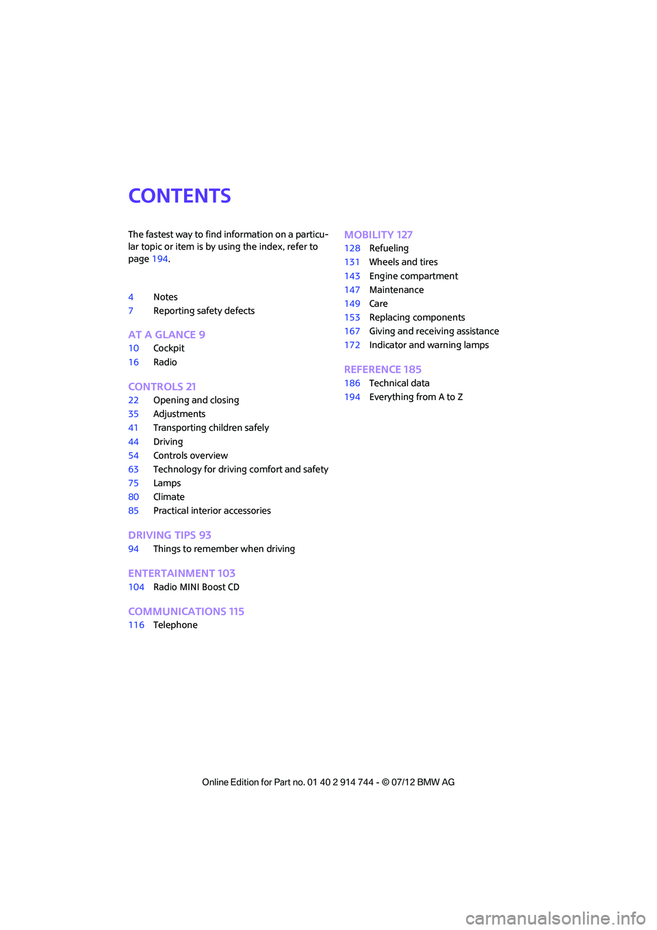
The fastest way to find information on a particu-
lar topic or item is by using the index, refer to
page194.
4 Notes
7 Reporting safety defects
AT A GLANCE 9
10Cockpit
16 Radio
CONTROLS 21
22Opening and closing
35 Adjustments
41 Transporting children safely
44 Driving
54 Controls overview
63 Technology for drivin g comfort and safety
75 Lamps
80 Climate
85 Practical interior accessories
DRIVING TIPS 93
94Things to remember when driving
ENTERTAINMENT 103
104Radio MINI Boost CD
COMMUNICATIONS 115
116Telephone
MOBILITY 127
128Refueling
131 Wheels and tires
143 Engine compartment
147 Maintenance
149 Care
153 Replacing components
167 Giving and receiving assistance
172 Indicator and warning lamps
REFERENCE 185
186Technical data
194 Everything from A to Z
Online Edition for Part no. 01 40 2 914 744 - \251 07/12 BMW AG
Page 5 of 207
Notes
4
Notes
Using this Owner's
Manual
We have tried to make all the information in this
Owner's Manual easy to find. The fastest way to
find specific topics is to refer to the detailed
index at the back of the manual. If you wish to
gain an initial overview of your vehicle, you will
find this in the first chapter.
Should you wish to sell yo ur MINI at some time in
the future, remember to hand over this Owner's
Manual to the new owner; it is an important part
of the vehicle.
Additional sources of information
Should you have any other questions, your MINI
dealer will be glad to advise you at any time.
You can find more information about the MINI,
for example on its technology, on the Internet at
www.MINI.com.
Symbols used
Indicates precautions that must be
followed precisely in order to avoid the
possibility of personal injury and serious
damage to the vehicle. <
Indicates information that will assist you in
gaining the optimum benefit from your
vehicle and enable you to care more effectively
for your vehicle. <
Refers to measures that can be taken to
help protect the environment. <
< Marks the end of a specific item of informa-
tion.
"..." Identifies radio display texts used to select
individual functions.
Symbols on vehicle components
Indicates that you should consult the rele-
vant section of this Owner's Manual for
information on a particular part or assembly.
Vehicle equipment
The manufacturer of your MINI is the Bayerische
Motoren Werke Aktien gesellschaft, BMW AG.
This Owner's Manual describes all models as well
as all production, country and special equip-
ment that is offered in the model range. Equip-
ment is also described that is not available
because of, for example, selected options or
country version. This also applies to safety
related functions and systems. For equipment
and models that are not described in this
Owner's Manual, please see the supplementary
Owner's Manuals that are provided.
Status of this Owner's
Manual at time of
printing
The high level of safety and quality of the MINI
vehicles is ensured through continuous develop-
ment. In rare cases, there may be differences
between the description and the vehicle.
For your safety
Maintenance and repair
Advanced technology, e.g. the use of
modern materials and high-performance
electronics, requires specially adapted mainte-
nance and repair methods. Therefore, have the
necessary work on your MI NI only carried out by
a MINI dealer or a work shop that has specially
trained personnel workin g in accordance with
Online Edition for Part no. 01 40 2 914 744 - \251 07/12 BMW AG
Page 6 of 207
Notes
5
the specifications of the MINI manufacturer. If
this work is not carried out properly, there is a
danger of subsequent damage and related
safety hazards.<
Parts and accessories
For your own safety, use genuine parts
and accessories approved by the manu-
facturer of the MINI.
When you purchase accessories tested
and approved by the manufacturer of the MINI
and Original MINI Parts, you simultaneously
acquire the assurance that they have been thor-
oughly tested by the manufacturer of the MINI
to ensure optimum performance when installed
on your vehicle.
The manufacturer of the MINI warrants these
parts to be free from defects in material and
workmanship.
The manufacturer of the MINI will not accept any
liability for damage result ing from installation of
parts and accessories not approved by the
manufacturer of the MINI.
The manufacturer of the MINI cannot test every
product made by other manufacturers to verify
if it can be used on a MINI safely and without risk
to either the vehicle, its operation, or its occu-
pants.
Original MINI Parts, MINI Accessories and other
products approved by the manufacturer of the
MINI, together with professional advice on using
these items, are available from all MINI dealers.
Installation and operation of accessories that
have not been approved by the manufacturer of
your MINI, such as alarms, radios, amplifiers,
radar detectors, wheels, suspension compo-
nents, brake dust shield s, telephones, including
operation of any mobile phone from within the
vehicle without using an externally mounted
antenna, or transceiver equipment, for instance,
CBs, walkie-talkies, ham radios or similar acces-
sories, may cause extensiv e damage to the vehi-
cle, compromise its safe ty, interfere with the
vehicle's electrical s y s t e m o r a f f e c t t h e v a l i d i t y o f the MINI Limited Warranty. See your MINI dealer
for additional information.
<
Maintenance, replacement, or repair of
the emission control devices and systems
may be performed by any automotive repair
establishment or individu al using any certified
automotive part. <
California Proposition 65 warning
California law requires us to issue the following
warning:
Engine exhaust and a wide variety of
automobile components and parts,
including components foun d in the interior fur-
nishings in a vehicle, contain or emit chemicals
known to the State of California to cause cancer
and birth defects and reproductive harm. In
addition, certain fluids co ntained in vehicles and
certain products of component wear contain or
emit chemicals known to the State of California
to cause cancer and birth defects or other repro-
ductive harm.
Battery posts, terminals and related accessories
contain lead and lead compounds. Wash your
hands after handling.
Used engine oil contains chemicals that have
caused cancer in laboratory animals. Always
protect your skin by washing thoroughly with
soap and water.<
Service and warranty
We recommend that you read this publication
thoroughly.
Your MINI is covered by the following warran-
ties:
> New Vehicle Limited Warranty
> Rust Perforation Limited Warranty
> Federal Emissions System Defect Warranty
> Federal Emissions Performance Warranty
> California Emission Control System Limited
Warranty
Online Edition for Part no. 01 40 2 914 744 - \251 07/12 BMW AG
Page 7 of 207
Notes
6
Detailed information about these warranties is
listed in the Service and Warranty Information
Booklet for US models or in the Warranty and
Service Guide Booklet for Canadian models.
Your vehicle has been specifically adapted and
designed to meet the particular operating con-
ditions and registration requirements in your
country and continental region in order to
deliver the full driving pleasure while the vehicle
is operated under those conditions. If you wish
to operate your vehicle in another country or
region, you may be requ ired to adapt your
vehicle to meet different prevailing operating
conditions and registration requirements. You
should also be aware of any applicable warranty
limitations or exclusions for such country or
region. In such a case, please contact Customer
Relations for further information.
Maintenance
Maintain the vehicle regularly to sustain road
safety, operational reliability and the New
Vehicle Limited Warranty.
Specifications for required maintenance mea-
sures:
> MINI Maintenance System
> Service and Warranty Information Booklet
for US models
> Warranty and Service Guide Booklet for
Canadian models
If the vehicle is not ma intained according to
these specifications, this could result in serious
damage to the vehicle. Such damage is not cov-
ered by the MINI New Vehicle Limited Warranty.
Data memory
A variety of electronic components in your vehi-
cle include data storage devices, which store
technical information on the condition of your
vehicle, events and errors, either temporarily or
permanently. In general, this technical informa-
tion documents the condition of a component, a
module, a system or the surroundings: >
Operating conditions of system compo-
nents, e.g., fill levels.
> Status messages regarding the vehicle and
of its individual comp onents, such as wheel
rpm/vehicle speed, response delay, lateral
acceleration.
> Malfunctions and defects in the major
system components, such as the lights and
brakes.
> Responses of the vehicle in special driving
situations, such as th e deployment of an
airbag, the utilization of stability control
systems.
> Environmental conditio ns, such as tempera-
ture.
These data are exclusively of a technical nature
and are used for the detection and correction of
errors, as well as the optimization of vehicle
functions. Motion profiles of traveled routes can
not be deduced from these data. If services are
required, such as repair services, service pro-
cesses, warranty claims an d quality assurance,
then this technical info rmation can be read out
by employees of service departments, including
the manufacturer, from the event and error data
storage devices by usin g special diagnostic
equipment. There, if necessary, you will receive
further information. Afte r remedying an error,
the information in the error memory is deleted
or progressively overwritten.
When using the vehicle, situations are conceiv-
able in which this techni cal data, in conjunction
with other information, su ch as accident reports,
vehicle damage, witness statements, etc. - pos-
sibly with the assistance of an expert - could be
traced to particular individuals. Additional func-
tions that are agreed upon contractually with
the customer, such as vehi cle tracking in case of
emergency, permit the transmission of certain
vehicle data from the vehicle.
Online Edition for Part no. 01 40 2 914 744 - \251 07/12 BMW AG
Page 61 of 207

CONTROLSControls overview
60
Displaying vehicle check
For certain maintenance operations, you can
view the respective distance remaining or due
date individually in the tachometer.
1.Switch on the ignition, refer to page 44.
2. Press the button in the turn signal indicator
as often as necessary until "SET/INFO" is
displayed.
3. Press and hold the button until the display
changes.
4. Press the button repeatedly until the corre-
sponding symbol and "SERVICE- INFO" are
displayed.
5. Press and hold the button until the display
changes.
6. Press the button to display the individual
service items, refer to the following informa-
tion.
Possible displays
1 Button for selecting information
SymbolFunction
Engine oil
Front brakes
Rear brakes
Road worthiness test
Vehicle check
Online Edition for Part no. 01 40 2 914 744 - \251 07/12 BMW AG
Page 62 of 207
Controls overviewCONTROLS
61
More information on the MINI Maintenance
System can be found on page 147.
Clock
Setting the time
Radio MINI Boost CD:
1.Press the MENU button.
2. Press the button.
3. Press the button.
4. Select the desired menu item, "FORMAT",
"HRS" or "MIN", and then press the button.
5. Turn the knob on the right to set values.
6. Press the knob on the right to store values.
7. Press the button to exit setting
values.
Date
Setting date
Radio MINI Boost CD:
1. Press the MENU button.
2. Press the button.
3. Press the button.
4. Select the desired menu item "DD", "MM" or
"YY".
5. Turn the knob on the right to set values.
6. Press the knob on the right to store values.
7. Press the button to exit setting
values.
Check Control
The concept
The Check Control monitors vehicle functions
and alerts you to any malfunctions in the
systems monitored. Check Control messages
involve indicator or warning lamps in the
displays and, in some circumstances, an acoustic
signal.
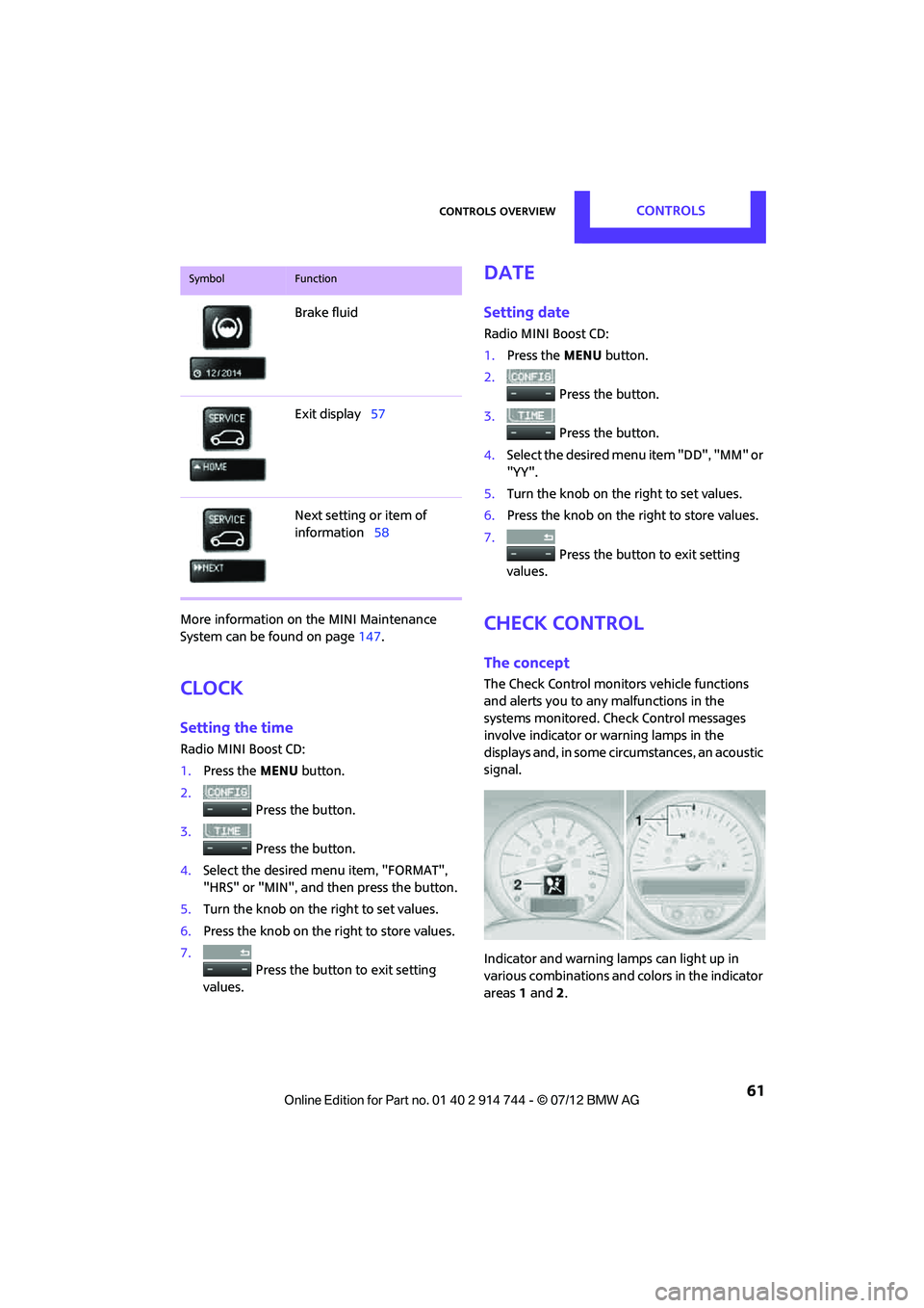
Indicator and warning lamps can light up in
various combinations and colors in the indicator
areas 1 and 2.
Brake fluid
Exit display
57
Next setting or item of
information 58
SymbolFunction
Online Edition for Part no. 01 40 2 914 744 - \251 07/12 BMW AG
Page 72 of 207

Technology for driving comfort and safetyCONTROLS
71
Drive cautiously and do not exceed a
speed of 50 mph/80 km/h.
A loss of tire inflation pressure results in a
change in the handling characteristics, e.g.
reduced lane stability du ring braking, a longer
braking distance and altered self-steering
properties. <
Vibrations or loud noises while driving can
indicate complete failure of the tire.
Reduce your speed and bring the vehicle to a
stop; otherwise, pieces of tire may come off,
which could result in an accident. Do not con-
tinue driving and contact your MINI dealer. <
Malfunction
The small warning lamp flashes in
yellow and then lights up continuously;
the larger warning lamp lights up in
yellow.
No punctures can be detected.
Display in the following situations:
> Wheel without TPM electronics is mounted:
If need be, have it checked by your MINI
dealer.
> Malfunction:
Have the system checked.
> TPM was unable to complete the resetting
procedure; reset the system again.
The small warning lamp flashes in
yellow and then lights up continuously;
the larger warning lamp lights up in
yellow. No punctures can be detected.
Display in the following situation:
> Malfunction because of other equipment or
devices, same radio frequency:
After leaving the interference area, the
system is again active automatically.
Declaration according to NHTSA/
FMVSS 138 Tire Pressure Monitoring
Systems
Each tire, including the spare, should be
checked monthly when cold and inflated to the
inflation pressure recommended by the vehicle manufacturer on the vehicle placard or tire infla-
tion pressure label. If your vehicle has tires of a
different size than the
size indicated on the
vehicle placard or tire in flation pressure label,
you should determine the proper tire inflation
pressure for those tires. As an added safety fea-
ture, your vehicle has been equipped with a tire
pressure monitoring syst em TPMS that illumi-
nates a low tire pressure telltale when one or
more of your tires are significantly underin-
flated. Accordingly, when the low tire pressure
telltale illuminates, you should stop and check
your tires as soon as po ssible, and inflate them
to the proper pressure. Driving on a significantly
underinflated tire causes the tire to overheat
and can lead to tire failure. Underinflation also
reduces fuel efficiency and tire tread life, and
may affect the vehicle's handling and stopping
ability. Please note that the TPMS is not a substi-
tute for proper tire maintenance, and it is the
driver's responsibility to maintain correct tire
pressure, even if underi nflation has not reached
the level at which the TPMS low tire pressure tell-
tale illuminates.
The TPMS malfunction indicator is combined
with the low tire pressure telltale. When the sys-
tem detects a malfunction, the telltale will flash
for approximately one minute and then remain
continuously lit. This sequence will continue
upon subsequent vehicle startups as long as the
malfunction exists. When the malfunction indi-
cator is illuminated, the system may not be able
to detect or signal low tire pressure as intended.
TPMS malfunctions may occur for a variety of
reasons, including the in stallation of replace-
ment or alternate tires or wheels on the vehicle
that prevent the TPMS from functioning prop-
erly. Always check the TP MS malfunction telltale
after replacing one or mo re tires or wheels on
your vehicle to ensure that the replacement or
alternate tires and wheels allow the TPMS to
continue to function properly.
Online Edition for Part no. 01 40 2 914 744 - \251 07/12 BMW AG
Page 83 of 207
CONTROLSClimate
82
Air distribution
Direct the flow of air to the
windows , to the upper body
area or to the footwell .
Intermediate settings are possible.
Windshield heating
The windshield heating is switched
off automatically after a short time.
The front window heating is
lowered or switched off entirely to reduce the
drain on the battery.
Defrosting windows and removing
condensation
1. Set air flow rate to the maximum level.
2. Set air distribution to position .
Condensation is removed from the windows
more quickly when the cooling function is
also activated.
3. Set to the highest temperature, red.
4. Deactivate recirculated-air mode.
5. Turn on windshield heating if necessary.
6. Turn on rear window defroster if necessary.
Microfilter
The microfilter captures dust and pollen. The
microfilter is changed by your MINI dealer
during routine maintenance work.
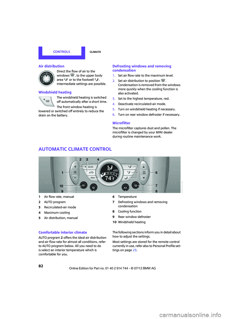
Automatic climate control
1Air flow rate, manual
2 AUTO program
3 Recirculated-air mode
4 Maximum cooling
5 Air distribution, manual 6
Temperature
7 Defrosting windows and removing
condensation
8 Cooling function
9 Rear window defroster
10 Windshield heating
Comfortable interior climate
AUTO program 2 offers the ideal air distribution
and air flow rate for almo st all conditions, refer
to AUTO program below. All you need to do
is select an interior temperature which is
comfortable for you. The following sections inform you in detail about
how to adjust the settings.
Most settings are stored
for the remote control
currently in use, refer also to Personal Profile set-
tings on page 23.
Online Edition for Part no. 01 40 2 914 744 - \251 07/12 BMW AG
Page 85 of 207
CONTROLSClimate
84
Defrosting windows and removing
condensation
Quickly removes ice and condensa-
tion from the windshield and front
side windows.
For this purpose, also switch on the
cooling function.
The windshield heating is switched on auto-
matically.
Windshield heating
The windshield heating is switched
off automatically after a certain
time.
Cooling function
When the cooling function is on,
the air is cooled, dried, then
reheated according to the
temperature setting. The passen-
ger compartment can only be
cooled while the engine is running.
The cooling function helps prevent condensa-
tion on the windows or removes it quickly.
Depending on the weather, the windshield may
fog over briefly when the engine is started. The
recirculated-air mode may be switched on auto-
matically.
When the AUTO button is pressed, the cooling
function switches on automatically.
Microfilter/activated-charcoal filter
The microfilter captures dust and pollen. The
activated-charcoal filter provides additional
protection by filtering gaseous pollutants from
the outside air. Your MINI dealer replaces this
combined filter as a standard part of your
scheduled maintenance.
You can call up further in formation in the service
requirements display, page 59.
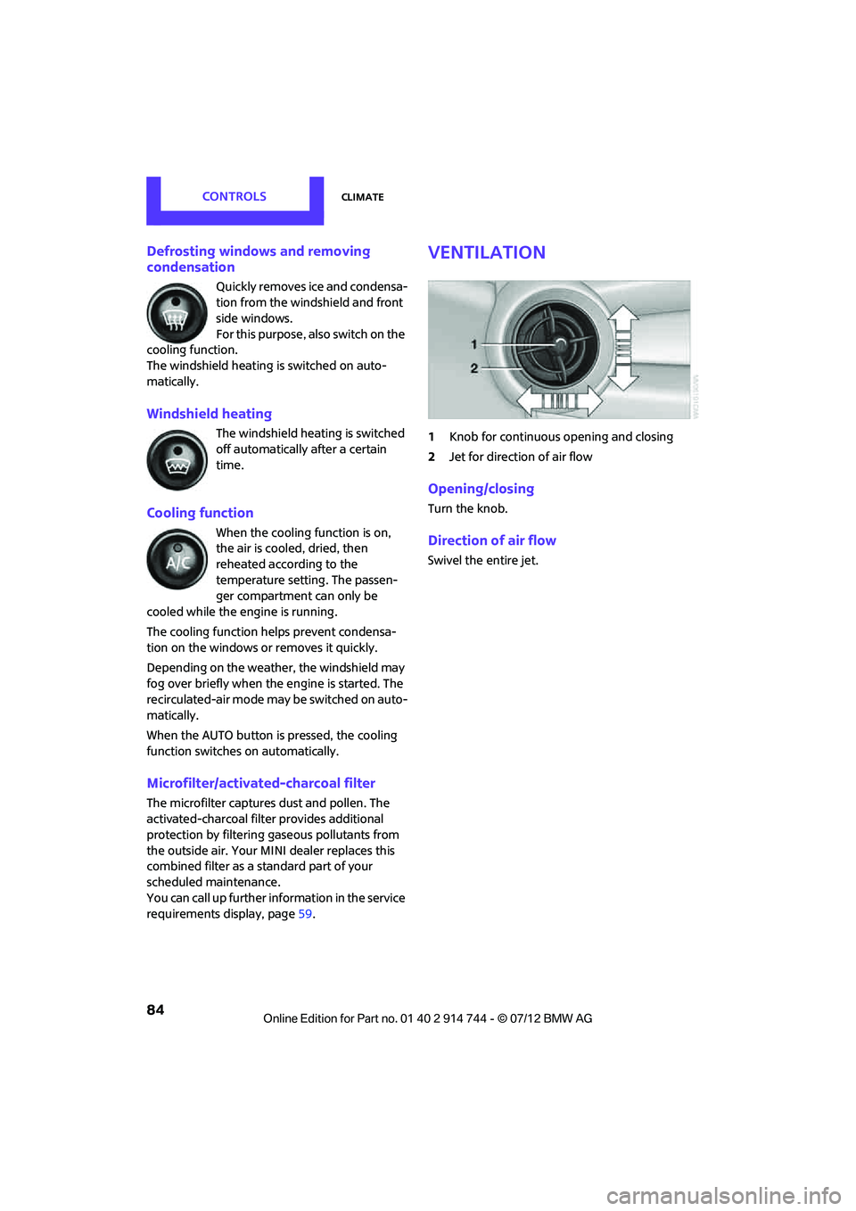
Ventilation
1 Knob for continuous opening and closing
2 Jet for direction of air flow
Opening/closing
Turn the knob.
Direction of air flow
Swivel the entire jet.
Online Edition for Part no. 01 40 2 914 744 - \251 07/12 BMW AG
Page 101 of 207
DRIVING TIPSThings to remember when driving
100
for attaching the cargo straps. Two of them
are located on the forward wall of the cargo
area.
Comply with the information enclosed with
the load-securing devices.
Always position and secure the cargo as
described above, so that it cannot endan-
ger the car's occupants, for example if sudden
braking or swerves are necessary.
Do not exceed the approved gross vehicle
weight and axle loads, page 191; otherwise, the
operating safety of the vehicle is no longer
assured and the vehicle will not be in compli-
ance with the construction and use regulations.
Heavy or hard objects should not be carried
loose inside the car, since they could be thrown
around, for example as a result of heavy braking,
sudden swerves, etc., and endanger the occu-
pants. Do not secure cargo using the fastening
points for the tether strap, page 42; they may
become damaged. <
Roof-mounted luggage
rack
A special rack system is available as an option for
your MINI. Your MINI dealer will be glad to
advise you. Comply with the installation instruc-
tions supplied with the rack system.
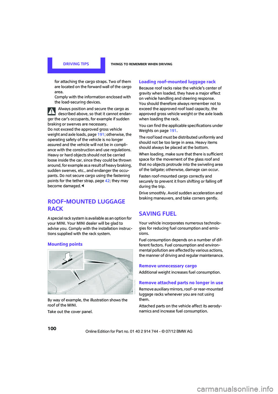
Mounting points
By way of example, the illustration shows the
roof of the MINI.
Take out the cover panel.
Loading roof-mounted luggage rack
Because roof racks raise the vehicle's center of
gravity when loaded, they have a major effect
on vehicle handling and steering response.
You should therefore always remember not to
exceed the approved roof load capacity, the
approved gross vehicle we ight or the axle loads
when loading the rack.
You can find the applicable specifications under
Weights on page 191.
The roof load must be distributed uniformly and
should not be too large in area. Heavy items
should always be placed at the bottom.
When loading, make sure that there is sufficient
space for the movement of the glass roof and
that no objects protrude into the swiveling area
of the tailgate; otherwise, damage can occur.
Fasten roof-mounted cargo correctly and
securely to prevent it from shifting or falling off
during the trip.
Drive smoothly. Avoid su dden acceleration and
braking maneuvers, and take corners gently.
Saving fuel
Your vehicle incorporates numerous technolo-
gies for reducing fuel consumption and emis-
sions.
Fuel consumption depends on a number of dif-
ferent factors. Fuel consumption and environ-
mental pollution are affect ed by various actions,
the manner of driving and regular maintenance.
Remove unnecessary cargo
Additional weight increases fuel consumption.
Remove attached parts no longer in use
Remove auxiliary mirrors, roof- or rear-mounted
luggage racks whenever you are not using
them.
Attached parts on the ve hicle affect its aerody-
namics and increase fuel consumption.
Online Edition for Part no. 01 40 2 914 744 - \251 07/12 BMW AG