sensor MINI COOPER 2013 Owners Manual
[x] Cancel search | Manufacturer: MINI, Model Year: 2013, Model line: COOPER, Model: MINI COOPER 2013Pages: 267, PDF Size: 3.53 MB
Page 34 of 267
Opening and closingCONTROLS
33
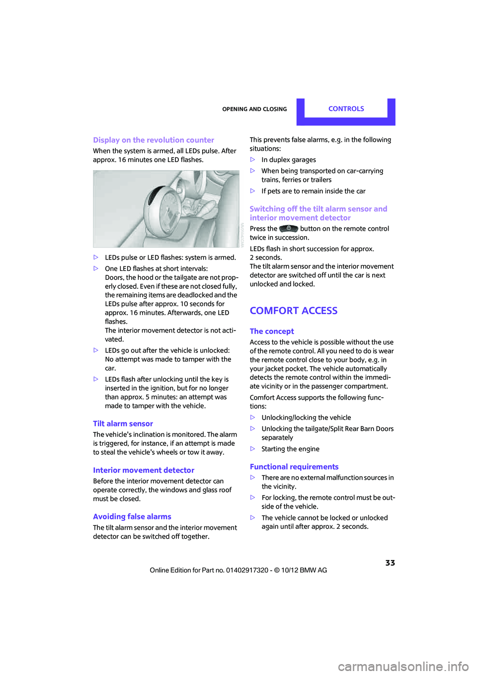
Display on the revolution counter
When the system is armed, all LEDs pulse. After
approx. 16 minutes one LED flashes.
>LEDs pulse or LED flashes: system is armed.
> One LED flashes at short intervals:
Doors, the hood or the tailgate are not prop-
erly closed. Even if these are not closed fully,
the remaining items are deadlocked and the
LEDs pulse after approx. 10 seconds for
approx. 16 minutes. Afterwards, one LED
flashes.
The interior movement detector is not acti-
vated.
> LEDs go out after the vehicle is unlocked:
No attempt was made to tamper with the
car.
> LEDs flash after unlocking until the key is
inserted in the ignition, but for no longer
than approx. 5 minutes: an attempt was
made to tamper with the vehicle.
Tilt alarm sensor
The vehicle's inclination is monitored. The alarm
is triggered, for instance, if an attempt is made
to steal the vehicle's wheels or tow it away.
Interior movement detector
Before the interior mo vement detector can
operate correctly, the windows and glass roof
must be closed.
Avoiding false alarms
The tilt alarm sensor an d the interior movement
detector can be swit ched off together. This prevents false alarms, e.g. in the following
situations:
>
In duplex garages
> When being transported on car-carrying
trains, ferries or trailers
> If pets are to remain inside the car
Switching off the tilt alarm sensor and
interior movement detector
Press the button on the remote control
twice in succession.
LEDs flash in short succession for approx.
2 seconds.
The tilt alarm sensor an d the interior movement
detector are switched of f until the car is next
unlocked and locked.
Comfort Access
The concept
Access to the vehicle is po ssible without the use
of the remote control. All you need to do is wear
the remote control close to your body, e.g. in
your jacket pocket. Th e vehicle automatically
detects the remote control within the immedi-
ate vicinity or in the passenger compartment.
Comfort Access supports the following func-
tions:
> Unlocking/locking the vehicle
> Unlocking the tailgate/Split Rear Barn Doors
separately
> Starting the engine
Functional requirements
>There are no external malfunction sources in
the vicinity.
> For locking, the remote control must be out-
side of the vehicle.
> The vehicle cannot be locked or unlocked
again until after approx. 2 seconds.
00320051004F004C00510048000300280047004C0057004C005200510003
Page 44 of 267
AdjustmentsCONTROLS
43
Interior and exterior mirrors,
automatic dimming feature
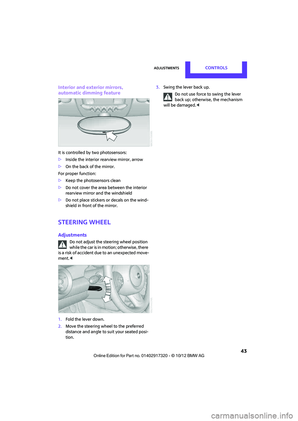
It is controlled by two photosensors:
>Inside the interior rearview mirror, arrow
> On the back of the mirror.
For proper function:
> Keep the photosensors clean
> Do not cover the area between the interior
rearview mirror and the windshield
> Do not place stickers or decals on the wind-
shield in front of the mirror.
Steering wheel
Adjustments
Do not adjust the steering wheel position
while the car is in motion; otherwise, there
is a risk of accident due to an unexpected move-
ment. <
1. Fold the lever down.
2. Move the steering wheel to the preferred
distance and angle to su it your seated posi-
tion. 3.
Swing the lever back up.
Do not use force to swing the lever
back up; otherwise, the mechanism
will be damaged. <
00320051004F004C00510048000300280047004C0057004C005200510003
Page 53 of 267
CONTROLSDriving
52
5.Move the selector lever into the desired
position by pressing the button on the front
of the selector lever.
Before manually unlo cking the selector
lever lock, firmly set the parking brake to
prevent the vehicle from rolling away. <
Turn signals/
headlamp flasher
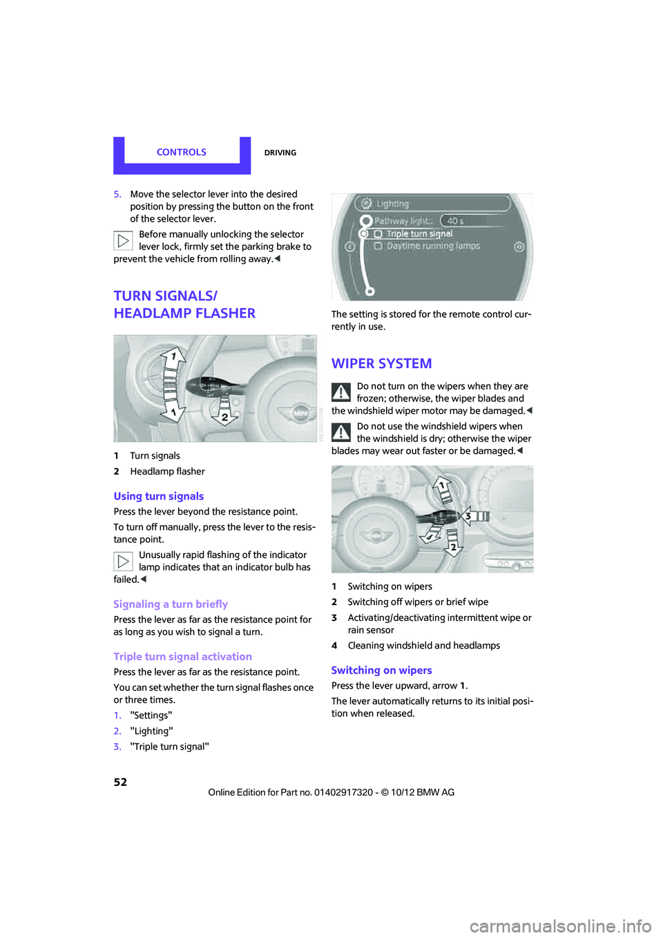
1Turn signals
2 Headlamp flasher
Using turn signals
Press the lever beyond the resistance point.
To turn off manually, press the lever to the resis-
tance point. Unusually rapid flashing of the indicator
lamp indicates that an indicator bulb has
failed. <
Signaling a turn briefly
Press the lever as far as the resistance point for
as long as you wish to signal a turn.
Triple turn signal activation
Press the lever as far as the resistance point.
You can set whether the turn signal flashes once
or three times.
1."Settings"
2. "Lighting"
3. "Triple turn signal" The setting is stored fo
r the remote control cur-
rently in use.
Wiper system
Do not turn on the wipers when they are
frozen; otherwise, th e wiper blades and
the windshield wiper motor may be damaged. <
Do not use the windshield wipers when
the windshield is dry; otherwise the wiper
blades may wear out faster or be damaged.<
1 Switching on wipers
2 Switching off wipers or brief wipe
3 Activating/deactivating intermittent wipe or
rain sensor
4 Cleaning windshield and headlamps
Switching on wipers
Press the lever upward, arrow 1.
The lever automatically returns to its initial posi-
tion when released.
00320051004F004C00510048000300280047004C0057004C005200510003
Page 54 of 267
DrivingCONTROLS
53
Normal wiper speed
Press once.
The system switches to intermittent operation
when the vehicle is stationary.
Fast wiper speed
Press twice or press beyo nd the resistance point.
The system switches to normal speed when the
vehicle is stationary.
Intermittent wipe or rain sensor
If the car is not equipped with a rain sensor, the
intermittent-wipe time is preset.
If the car is equipped with a rain sensor, the time
between wipes is contro lled automatically and
depends on the intensity of the rainfall. The rain
sensor is mounted on the windshield, directly in
front of the interior rearview mirror.
Activating intermittent wipe or rain
sensor
Press button, arrow 3.
This symbol is displayed in the
tachometer.
Deactivate the rain sensor before entering
an automatic car wash. Failure to do so
could result in damage caused by undesired
wiper activation. <
Adjusting the sensitivity of the rain
sensor
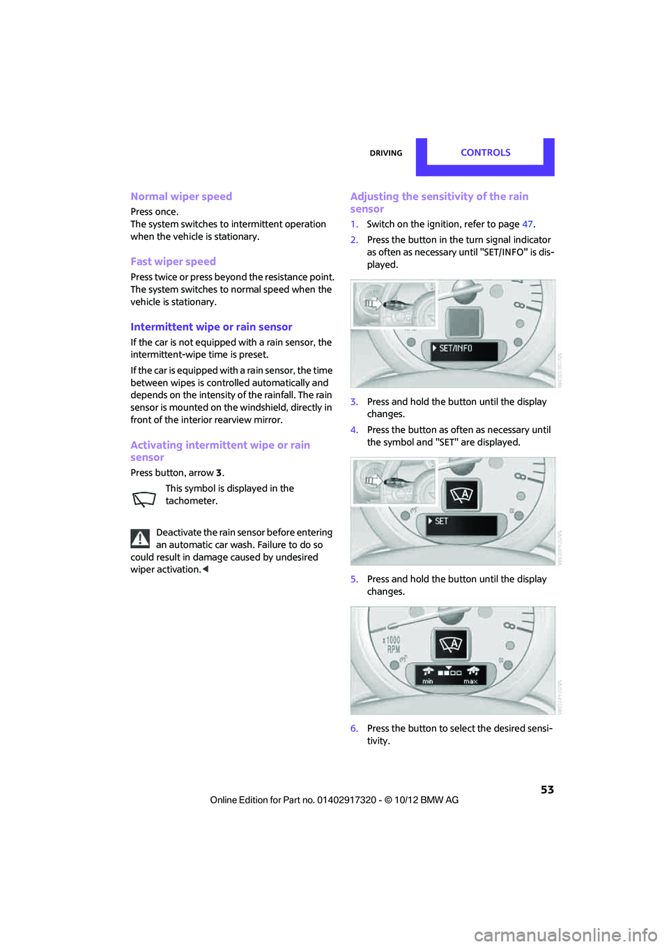
1.Switch on the ignition, refer to page 47.
2. Press the button in the turn signal indicator
as often as necessary until "SET/INFO" is dis-
played.
3. Press and hold the butt on until the display
changes.
4. Press the button as of ten as necessary until
the symbol and "SET" are displayed.
5. Press and hold the butt on until the display
changes.
6. Press the button to select the desired sensi-
tivity.
00320051004F004C00510048000300280047004C0057004C005200510003
Page 55 of 267

CONTROLSDriving
54
7.Wait, or press and hold the button until the
display changes.
The settings are stored.
Deactivating intermittent wipe or rain
sensor
Press the button again, arrow 3.
Brief wipe
Press the lever downward once, arrow 2.
Cleaning windshield and headlamps
Pull the lever, arrow 4.
Washer fluid is sprayed onto the windshield and
the wipers are operated briefly.
When the vehicle lighting system is switched on,
the headlamps are cleaned at regular and
appropriate intervals.
In cars equipped with an alarm system, the
headlamps cannot be cleaned when the hood is
open. Do not use the washers when the washer
fluid reservoir is emp ty; otherwise, you will
damage the washer pump.
Only use the washers if the hood has been com-
pletely closed; otherwise, the headlamp washer
system may be damaged. Do not use the wash-
ers if there is any danger that the fluid will freeze
on the windshield. If you do, your vision could be
obscured. For this reason, use antifreeze. <
Window washer nozzles
The window washer nozzles are heated auto-
matically while the engine is running or the igni-
tion is switched on.
Rear window wiper
0Rear wipers parked
1 To switch on intermittent wipe :
Turn the cap to level 1.
Operation is continuous in reverse gear.
The rear wiper does not move if the cap is in
interval stage 1 before the ignition is switched
on.
Cleaning the rear window
2 To clean the rear window during intermit-
tent wipe :
Turn the cap further to level 2 and hold it
there.
3 To clean the rear window when wipers are
parked :
Turn the cap to level 3 and hold it there.
Do not use the washers when the washer
fluid reservoir is emp ty; otherwise, you will
damage the washer pump. <
Washer fluid
Washer fluid is flammable. Keep it away
from ignition sources, only store it in the
closed, original container, and keep out of reach
of children; otherwise, there is a danger of
injury. Comply with the instructions on the con-
tainer. <
00320051004F004C00510048000300280047004C0057004C005200510003
Page 61 of 267
CONTROLSControls overview
60
Settings and information
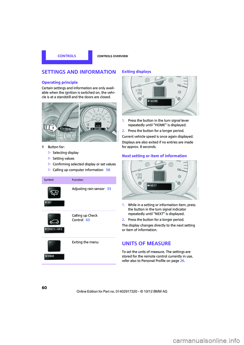
Operating principle
Certain settings and information are only avail-
able when the ignition is switched on, the vehi-
cle is at a standstill and the doors are closed.
1 Button for:
>Selecting display
> Setting values
> Confirming selected display or set values
> Calling up computer information 58
Exiting displays
1.Press the button in the turn signal lever
repeatedly until "HOME" is displayed.
2. Press the button for a longer period.
Current vehicle speed is once again displayed.
Displays are also exited if no entries are made
for approx. 8 seconds.
Next setting or item of information
1. While in a setting or information item, press
the button in the turn signal indicator
repeatedly until "NEXT" is displayed.
2. Press the button for a longer period.
The display changes direct ly to the next setting
or item of information.
Units of measure
To set the units of measure. The settings are
stored for the remote co ntrol currently in use,
refer also to Personal Profile on page 26.
SymbolFunction
Adjusting rain sensor53
Calling up Check
Control 63
Exiting the menu
00320051004F004C00510048000300280047004C0057004C005200510003
Page 69 of 267
CONTROLSTechnology for driving comfort and safety
68
Technology for driving comfort and
safety
Vehicle equipment
In this chapter, all production, country, and
optional equipment that is offered in the model
range is described. Equipment is also described
that is not available because of, for example,
selected options or coun try version. This also
applies to safety relate d functions and systems.
Park Distance Control
PDC
The concept
PDC assists you with parking in reverse. Acoustic
signals and a visual indi cator warn you of the
presence of an object behind the vehicle. To
measure the distance, there are four ultrasonic
sensors in either bumper.
These sensors have a range of approx.
6.5 ft/2 m. However, an acoustic warning
does not sound until an object is approx. 24 in/
60 cm from the rear corner sensors, or approx.
5 ft/1.50 m from the rear center sensors.PDC is a
parking aid that can indicate objects when they
are approached slowly, as is usually the case
when parking. Avoid appr oaching an object at
high speed; otherwise, physical circumstances
may lead to the system warning being issued
too late. <
Automatic mode
With the engine running or the ignition switched
on, the system is activated automatically after
approx. 1 second when you engage reverse
gear or move the automatic transmission selec-
tor lever to position R. Wait this short period
before driving.
Acoustic signals
As the distance between vehicle and object
decreases, the intervals between the tones
become shorter. If the distance to the nearest
object falls to below roughly 1 ft/30 cm, then a
continuous tone sounds.
If the distance remains co nstant, e.g. when driv-
ing parallel to a wall, the acoustic signal stops
after approx. 3 seconds.
Malfunction
Indicator lamp lights up. PDC has failed.
A message appears on the Control Dis-
play. Have the system checked.
To avoid this problem, keep the sensors clean
and free of ice or snow in order to ensure that
they will continue to operate effectively. When
using a high-pressure cleaner, do not direct the
jet toward the sensors for lengthy periods and
only spray from a distance of at least 4 in/10 cm.
PDC with visual warning
To have the system show distances to objects on
the Control Display. The contours of distant
objects are shown on the Control Display even
before the acoustic sign al sounds. The display
appears on the Control Display as soon as the
transmission is shifted into reverse or the selec-
tor lever is moved into the R position.
System limitations
Even with PDC, final responsibility for esti-
mating the distance between the vehicle
and any obstructions always remains with the
driver. Sensors, too, have blind spots in which
objects cannot be dete cted. Moreover, ultra-
sonic detection can reach its physical limits with
objects such as trailer tow bars and couplings,
thin and wedge-shaped objects, etc. Low
objects already indicated, such as curbs, may
00320051004F004C00510048000300280047004C0057004C005200510003
Page 70 of 267
Technology for driving comfort and safetyCONTROLS
69
enter the sensors' blind spots before or after a
continuous audible signal is given. Higher, pro-
truding objects, such as wall ledges, may not be
detectable. Therefore, always drive cautiously;
otherwise, there is a risk of personal injury or
property damage. Loud sound sources outside
or inside the car can drown out the PDC signal. <
Driving stability control
systems
Your MINI has a number of systems that help to
maintain the vehicle's st ability even in adverse
driving conditions.
The laws of physics cannot be repealed,
even with driving stability control systems.
An appropriate driving style always remains the
responsibility of the driver. Therefore do not
reduce the additional safety margin by engaging
in hazardous driving thereby running the risk of
an accident. <
Antilock Brake System ABS
ABS prevents locking of the wheels during brak-
ing. Safe steering respon se is maintained even
during full braking. Act ive safety is thus
increased.
Braking safely, refer to page 101.
ABS is operational every time you start the
engine.
Cornering Brake Control CBC
Driving stability and steering characteristics are
further enhanced while braking in turns or dur-
ing a lane change.
Electronic brake-forc e distribution EBV
The system controls the brake pressure in the
rear wheels to ensure stable braking behavior.
Brake Assist
Rapidly depressing the brake causes this system
to automatically develop maximum braking force. Thus, the system helps keep braking dis-
tance to a minimum. At the same time, all the
benefits provided by ABS are exploited.
Do not reduce the pressure on the brake for the
duration of the full braking application.
Dynamic Stability Control DSC
The concept
DSC prevents the driving wheels from losing
traction when you pull away from rest or accel-
erate.
DSC also detects unstable driving conditions
such as when the vehicle'
s rear end fishtails or
the vehicle is sliding on its front wheels. In these
cases, DSC helps the vehicle maintain a safe
course within physical limits by reducing engine
output and through brakin g actions at the indi-
vidual wheels.
Every time that the engine is started, DSC is
ready to operate.
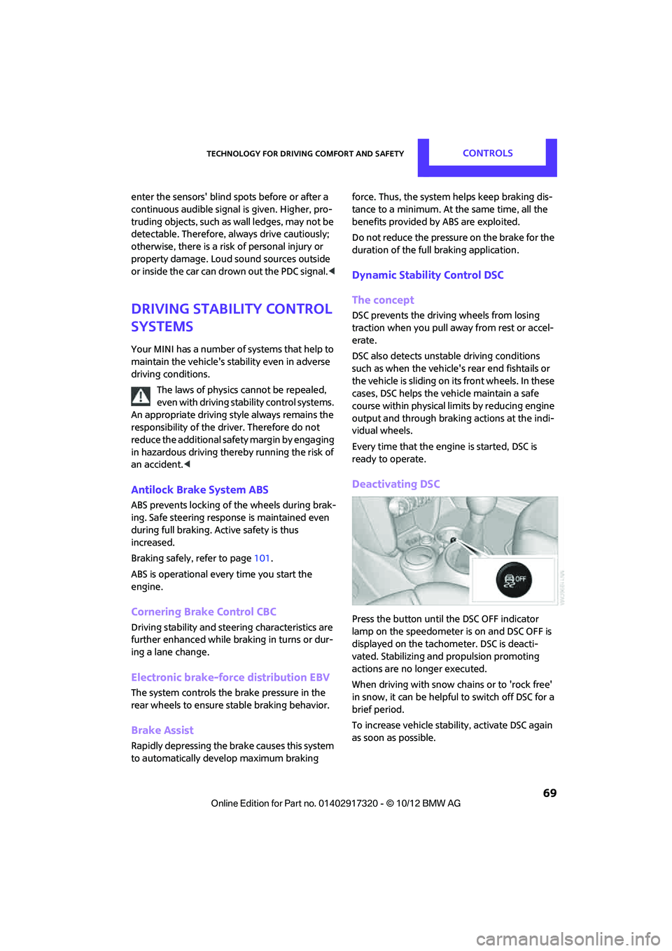
Deactivating DSC
Press the button until the DSC OFF indicator
lamp on the speedometer is on and DSC OFF is
displayed on the tachometer. DSC is deacti-
vated. Stabilizing and propulsion promoting
actions are no longer executed.
When driving with snow chains or to 'rock free'
in snow, it can be helpfu l to switch off DSC for a
brief period.
To increase vehicle stability, activate DSC again
as soon as possible.
00320051004F004C00510048000300280047004C0057004C005200510003
Page 111 of 267
NAVIGATIONNavigation system
110
Navigation system
Vehicle equipment
In this chapter, all production, country, and
optional equipment that is offered in the model
range is described. Equipment is also described
that is not available because of, for example,
selected options or coun try version. This also
applies to safety relate d functions and systems.
General information
The navigation system can determine the pre-
cise position of the vehicle, with the aid of satel-
lites and vehicle sensors, and can reliably guide
you to every entered destination.
Enter data only with the vehicle station-
ary, and always give priority to the appli-
cable traffic regulations in the event of any con-
tradiction between traffic and road conditions
and the instructions issu ed by the navigation
system. Failure to take to this precaution can
place you in violation of the law and put vehicle
occupants and other ro ad users in danger.<
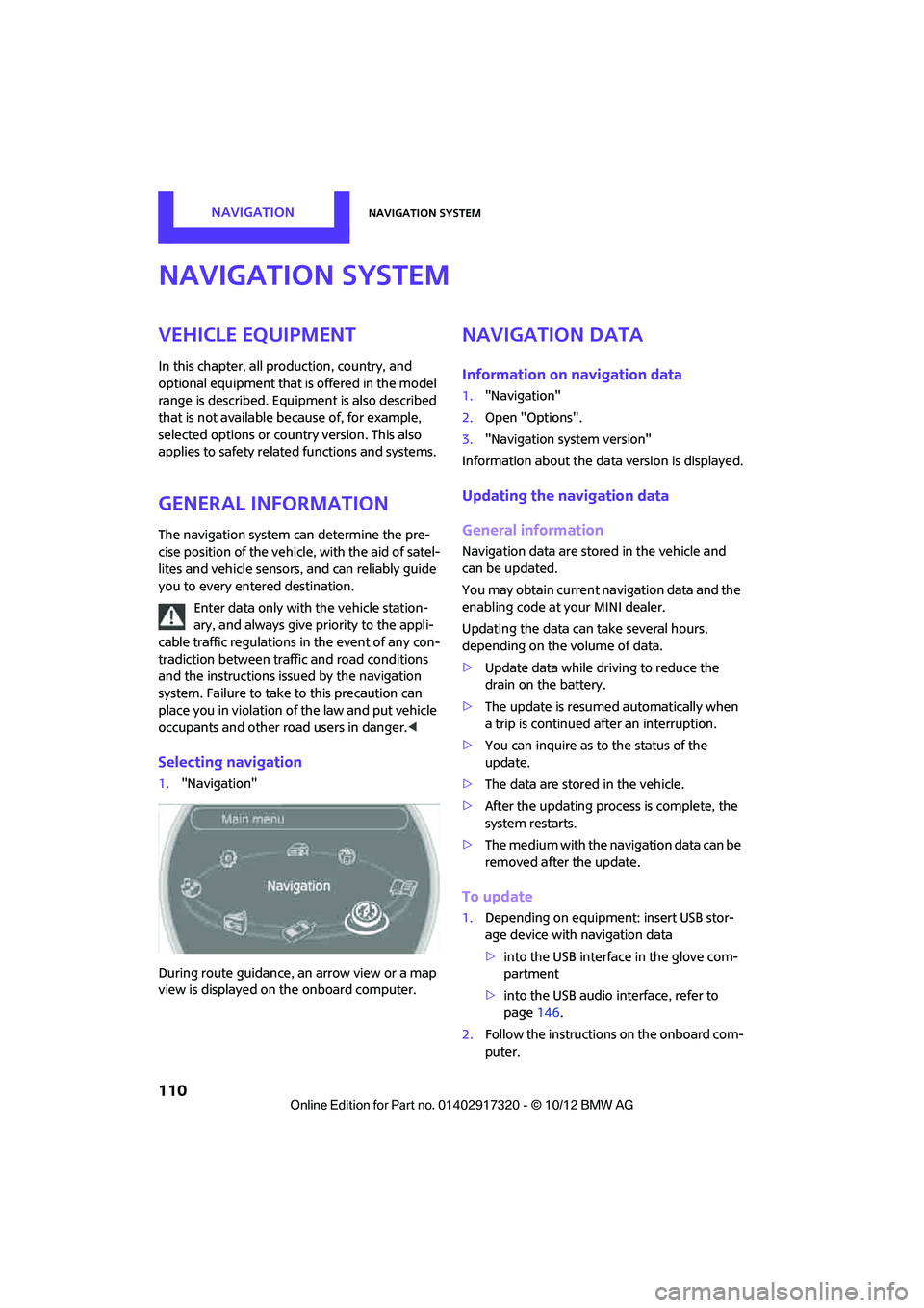
Selecting navigation
1."Navigation"
During route guidance, an arrow view or a map
view is displayed on the onboard computer.
Navigation data
Information on navigation data
1. "Navigation"
2. Open "Options".
3. "Navigation system version"
Information about the data version is displayed.
Updating the navigation data
General information
Navigation data are stored in the vehicle and
can be updated.
You may obtain current navigation data and the
enabling code at your MINI dealer.
Updating the data can take several hours,
depending on the volume of data.
> Update data while driving to reduce the
drain on the battery.
> The update is resumed automatically when
a trip is continued after an interruption.
> You can inquire as to the status of the
update.
> The data are stored in the vehicle.
> After the updating process is complete, the
system restarts.
> The medium with the na vigation data can be
removed after the update.
To update
1. Depending on equipment: insert USB stor-
age device with navigation data
>into the USB interface in the glove com-
partment
> into the USB audio interface, refer to
page 146.
2. Follow the instructions on the onboard com-
puter.
00320051004F004C00510048000300280047004C0057004C005200510003
Page 212 of 267

MaintenanceMOBILITY
211
Maintenance
Vehicle equipment
In this chapter, all production, country, and
optional equipment that is offered in the model
range is described. Equipment is also described
that is not available because of, for example,
selected options or count ry version. This also
applies to safety related functions and systems.
MINI Maintenance System
The MINI Maintenance System will remind you
of necessary maintenance measures and by
doing so, will assist you in maintaining the traffic
and operating safety of your vehicle.
If and when you come to sell your MINI, a com-
prehensive record of servicing will prove a signif-
icant benefit.
Condition Based Service CBS
Sensors and special algori thms take the different
driving conditions of your MINI into account.
Condition Based Service uses this to determine
the current and future se rvice requirements. By
letting you define a service and maintenance
regimen that reflects your own individual
requirements, the system builds the basis for
trouble-free driving.
On the Control Display, you can have the
remaining times or distan ces for selected main-
tenance tasks and any legally prescribed dates
displayed, page 61.
Service data in the remote control
Your vehicle continuously stores service-
requirement info rmation in the remote control
while you are driving. Your MINI dealer can read
out this data from the remote control unit, and
propose an optimized maintenance approach.
Whenever you take your car in for servicing you
should therefore hand your MINI dealer the
remote control unit that you last used.
Make sure that the date is always set cor-
rectly, page 63; otherwise, the effective-
ness of Condition Based Service CBS is not
assured. <
Service and Warranty Information
Booklet for US models and Warranty and
Service Guide Booklet for Canadian
models
Please consult your Service and Warranty Infor-
mation Booklet for US models and Warranty and
Service Guide Booklet for Canadian models for
additional information on service requirements.
The manufacturer of the MINI recom-
mends that you have service and repair
operations performed at your MINI dealer.
Take the time to ensure that these service pro-
cedures are confirmed by entries in your vehi-
cle's Service and Warranty Information Booklet
for US models and Warranty and Service Guide
Booklet for Canadian models. These entries ver-
ify that your vehicle has received the specified
regular maintenance. <
00320051004F004C00510048000300280047004C0057004C005200510003