brake MINI COOPER 2013 Owners Manual
[x] Cancel search | Manufacturer: MINI, Model Year: 2013, Model line: COOPER, Model: MINI COOPER 2013Pages: 267, PDF Size: 3.53 MB
Page 6 of 267
Notes
5
nance and repair methods. Therefore, have the
necessary work on your MINI only carried out by
a MINI dealer or a work shop that has specially
trained personnel workin g in accordance with
the specifications of the MINI manufacturer. If
this work is not carried out properly, there is a
danger of subsequent damage and related
safety hazards. <
Parts and accessories
For your own safety, use genuine parts
and accessories approved by the manu-
facturer of the MINI.
When you purchase accessories tested
and approved by the manufacturer of the MINI
and Original MINI Parts, you simultaneously
acquire the assurance that they have been thor-
oughly tested by the manufacturer of the MINI
to ensure optimum performance when installed
on your vehicle.
The manufacturer of the MINI warrants these
parts to be free from defects in material and
workmanship.
The manufacturer of the MINI will not accept any
liability for damage result ing from installation of
parts and accessories not approved by the man-
ufacturer of the MINI.
The manufacturer of the MINI cannot test every
product made by other manufacturers to verify
if it can be used on a MINI safely and without risk
to either the vehicle, its operation, or its occu-
pants.
Original MINI Parts, MINI Accessories and other
products approved by the manufacturer of the
MINI, together with professional advice on using
these items, are available from all MINI dealers.
Installation and operation of accessories that
have not been approved by the manufacturer of
your MINI, such as alarms, radios, amplifiers,
radar detectors, wheels, suspension compo-
nents, brake dust shield s, telephones, including
operation of any mobile phone from within the
vehicle without using an externally mounted
antenna, or transceiver equipment, for instance,
CBs, walkie-talkies, ham radios or similar acces- sories, may cause extensiv
e damage to the vehi-
cle, compromise its safety, interfere with the
vehicle's electrical s y s t e m o r a f f e c t t h e v a l i d i t y o f
the MINI Limited Warranty. See your MINI dealer
for additional information. <
Maintenance, replacement, or repair of
the emission control devices and systems
may be performed by any automotive repair
establishment or individu al using any certified
automotive part. <
California Proposition 65 warning
California law requires us to issue the following
warning:
Engine exhaust and a wide variety of
automobile components and parts,
including components foun d in the interior fur-
nishings in a vehicle, contain or emit chemicals
known to the State of California to cause cancer
and birth defects and reproductive harm. In
addition, certain fluids co ntained in vehicles and
certain products of component wear contain or
emit chemicals known to the State of California
to cause cancer and birth defects or other repro-
ductive harm.
Battery posts, terminals and related accessories
contain lead and lead compounds. Wash your
hands after handling.
Used engine oil contains chemicals that have
caused cancer in laboratory animals. Always
protect your skin by washing thoroughly with
soap and water.<
Service and warranty
We recommend that you read this publication
thoroughly.
Your MINI is covered by the following warran-
ties:
> New Vehicle Limited Warranty
> Rust Perforation Limited Warranty
> Federal Emissions System Defect Warranty
> Federal Emissions Performance Warranty
00320051004F004C00510048000300280047004C0057004C005200510003
Page 7 of 267
Notes
6
>California Emission Control System Limited
Warranty
Detailed information about these warranties is
listed in the Service and Warranty Information
Booklet for US models or in the Warranty and
Service Guide Booklet for Canadian models.
Your vehicle has been specifically adapted and
designed to meet the pa rticular operating con-
ditions and registration requirements in your
country and continental region in order to
deliver the full driving pleasure while the vehicle
is operated under those conditions. If you wish
to operate your vehicle in another country or
region, you may be required to adapt your vehi-
cle to meet different prevailing operating condi-
tions and registration re quirements. You should
also be aware of any a pplicable warranty limita-
tions or exclusions for such country or region. In
such a case, please contact Customer Relations
for further information.
Maintenance
Maintain the vehicle regularly to sustain road
safety, operational reliab ility and the New Vehi-
cle Limited Warranty.
Specifications for required maintenance mea-
sures:
> MINI Maintenance System
> Service and Warranty Information Booklet
for US models
> Warranty and Service Guide Booklet for
Canadian models
If the vehicle is not ma intained according to
these specifications, this could result in serious
damage to the vehicle. Such damage is not cov-
ered by the MINI New Vehicle Limited Warranty.
Data memory
A variety of electronic components in your vehi-
cle include data storage devices, which store
technical information on the condition of your
vehicle, events and errors, either temporarily or
permanently. In general, this technical informa- tion documents the condition of a component, a
module, a system or
the surroundings:
> Operating conditions of system compo-
nents, e.g., fill levels.
> Status messages regarding the vehicle and
of its individual comp onents, such as wheel
rpm/vehicle speed, response delay, lateral
acceleration.
> Malfunctions and defects in the major sys-
tem components, such as the lights and
brakes.
> Responses of the vehicle in special driving
situations, such as the deployment of an air-
bag, the utilization of stability control sys-
tems.
> Environmental conditio ns, such as tempera-
ture.
These data are exclusively of a technical nature
and are used for the detection and correction of
errors, as well as the optimization of vehicle
functions. Motion profiles of traveled routes can
not be deduced from these data. If services are
required, such as repair services, service pro-
cesses, warranty claims an d quality assurance,
then this technical info rmation can be read out
by employees of service departments, including
the manufacturer, from the event and error data
storage devices by usin g special diagnostic
equipment. There, if necessary, you will receive
further information. Afte r remedying an error,
the information in the error memory is deleted
or progressively overwritten.
When using the vehicle, situations are conceiv-
able in which this techni cal data, in conjunction
with other information, su ch as accident reports,
vehicle damage, witness statements, etc. - pos-
sibly with the assistance of an expert - could be
traced to particular individuals. Additional func-
tions that are agreed upon contractually with
the customer, such as vehi cle tracking in case of
emergency, permit the transmission of certain
vehicle data from the vehicle.
00320051004F004C00510048000300280047004C0057004C005200510003
Page 8 of 267
Notes
7
Event data recorder EDR
This vehicle is equipped with an event data
recorder EDR. The main purpose of an EDR is to
record, in certain crash or crash-like situations
such as an air bag deployment or collision with a
road obstacle, data that will assist in under-
standing how a vehicle' s systems performed.
The EDR is designed to record data related to
vehicle dynamics and safe ty systems for a short
period of time, typically 30 seconds or less.
The EDR in this vehicle is designed to record data
such as:
> How various systems in your vehicle were
operating.
> Whether or not the driver and passenger
safety belts were fastened.
> How far, if at all, the driver was depressing
the accelerator and/or brake pedal.
> How fast the vehicle was traveling.
These data can help provide a better under-
standing of the circumstances in which crashes
and injuries occur.
EDR data are recorded by your vehicle only if a
nontrivial crash situation occurs; no data are
recorded by the EDR un der normal driving con-
ditions and no personal data, e. g., name, gen-
der, age, and crash location, are recorded.
However, other parties, such as law enforce-
ment, could combine the EDR data with the type
of personally identifying data routinely acquired
during a crash investigation.
Reading the data recorded by an EDR requires
special equipment and access to the vehicle or
the EDR. In addition to the vehicle manufac-
turer, other parties that have the special equip-
ment such as law enforcement, can read the
information if they have access to the vehicle or
the EDR.
Reporting safety defects
For US customers
The following applies only to vehicles owned
and operated in the US.
If you believe that your vehicle has a defect that
could cause a crash or could cause injury or
death, you should immediately inform the
National Highway Traffic Safety Administration,
NHTSA, in addition to notifying MINI of North
America, LLC, P.O. Box 1227, Westwood, New
Jersey 07675-1227, Telephone 1-800-831-
1117.
If NHTSA receives simi lar complaints, it may
open an investigation, and if it finds that a safety
defect exists in a group of vehicles, it may order
a recall and remedy campaign. However, NHTSA
cannot become involved in individual problems
between you, your dealer, or MINI of North
America, LLC.
To contact NHTSA, you may call the Vehicle
Safety Hotline toll-free at 1-888-327-4236 (TTY:
1-800-424-9153); go to http://www.safer-
car.gov; or write to: Administrator, NHTSA, 400
Seventh Street, SW., Washington, DC 20590. You
can also obtain other information about motor
vehicle safety from http://www.safercar.gov
For Canadian customers
Canadian customers who wish to report a
safety-related defect to Transport Canada,
Defect Investigations and Recalls, may tele-
phone the toll-free hotline 1-800-333-0510.
You can also obtain ot her information about
motor vehicle safety from http://www.tc.gc.ca/
roadsafety
00320051004F004C00510048000300280047004C0057004C005200510003
Page 14 of 267
CockpitAT A GLANCE
13
Indicator and warning
lamps
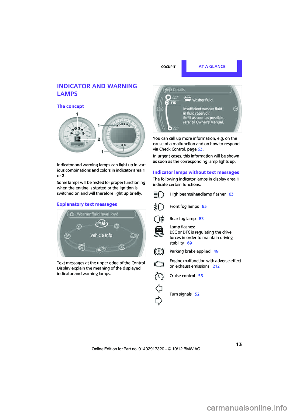
The concept
Indicator and warning lamps can light up in var-
ious combinations and colors in indicator area1
or 2.
Some lamps will be tested for proper functioning
when the engine is started or the ignition is
switched on and will therefore light up briefly.
Explanatory text messages
Text messages at the uppe r edge of the Control
Display explain the mean ing of the displayed
indicator and warning lamps. You can call up more information, e.g. on the
cause of a malfunction and on how to respond,
via Check Control, page
63.
In urgent cases, this information will be shown
as soon as the corresponding lamp lights up.
Indicator lamps without text messages
The following indicator lamps in display area 1
indicate certain functions:
High beams/headlamp flasher 83
Front fog lamps 83
Rear fog lamp 83
Lamp flashes:
DSC or DTC is regulating the drive
forces in order to maintain driving
stability 69
Parking brake applied 49
Engine malfunction with adverse effect
on exhaust emissions 212
Cruise control 55
Turn signals 52
00320051004F004C00510048000300280047004C0057004C005200510003
Page 35 of 267
CONTROLSOpening and closing
34
>The engine can only be started if the remote
control is in the vehicle.
> The doors and tailgate/Split Rear Barn Doors
must be closed to be able to operate the
windows and glass roof.
Comparison to standard remote controls
The indicated function can be operated by
pressing the buttons or via Comfort Access.
Instructions on opening and closing are found
starting on page 26.
If you notice a brief delay while opening or
closing the windows or glass roof, the sys-
tem is checking whether a remote control is
inside the vehicle. Repeat the opening or closing
procedure, if necessary. <
Unlocking
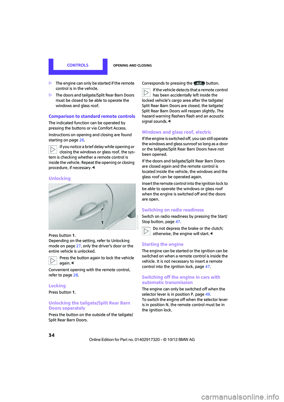
Press button 1.
Depending on the setting, refer to Unlocking
mode on page 27, only the driver's door or the
entire vehicle is unlocked.
Press the button again to lock the vehicle
again. <
Convenient opening with the remote control,
refer to page 28.
Locking
Press button 1.
Unlocking the tailgate/Split Rear Barn
Doors separately
Press the button on the outside of the tailgate/
Split Rear Barn Doors. Corresponds to pressing the button.
If the vehicle detects that a remote control
has been accidentally left inside the
locked vehicle's cargo area after the tailgate/
Split Rear Barn Doors are closed, the tailgate/
Split Rear Barn Doors will reopen slightly. The
hazard warning flashers flash and an acoustic
signal sounds. <
Windows and glass roof, electric
If the engine is switched off, you can still operate
the windows and glass sunr oof so long as a door
or the tailgate/Split Rear Barn Doors have not
been opened.
If the doors and tailgate /Split Rear Barn Doors
are closed again and th e remote control is
located inside the vehicle, the windows and the
glass roof can be operated again.
Insert the remote control into the ignition lock to
be able to operate the windows or glass roof
when the engine is swit ched off and the doors
are open.
Switching on radio readiness
Switch on radio readines s by pressing the Start/
Stop button, page 47.
Do not depress the brake or the clutch;
otherwise, the engine will start. <
Starting the engine
The engine can be started or the ignition can be
switched on when a remote control is inside the
vehicle. It is not necessary to insert a remote
control into the ignition lock, page 47.
Switching off the engine in cars with
automatic transmission
The engine can only be switched off when the
selector lever is in position P, page 49.
To switch the engine off when the selector lever
is in position N, the remote control must be in
the ignition lock.
00320051004F004C00510048000300280047004C0057004C005200510003
Page 36 of 267
Opening and closingCONTROLS
35
Before driving a vehicle with automatic
transmission into a car wash
1.Insert remote control into ignition lock.
2. Depress the brake.
3. Move the selector lever to position N.
4. Switch off the engine.
The vehicle can roll.
Malfunction
Comfort Access may malfunction due to local
radio waves, e. g. due to the presence of a
mobile phone in the immediate vicinity of the
remote control or the charging of a mobile
phone in the vehicle.
If this happens, open or close the vehicle via the
buttons on the remote control or using the inte-
grated key.
Insert the remote control into the ignition lock
and start the engine.
Warning lamps
The warning lamp lights up when an
attempt is made to start the engine: the
engine cannot be started. The remote
control is not inside the vehicle or is malfunc-
tioning. Take the remote control with you inside
the vehicle or have it checked. If necessary,
insert another remote co ntrol into the ignition
lock.
The warning lamp lights up when the
engine is running: th e remote control is
no longer inside the vehicle. After the
engine is switched off, the engine can only be
restarted within approx. 10 seconds.
The indicator lamp comes on and a mes-
sage appears on the Control Display:
replace the battery in the remote con-
trol.
Replacing the battery
The remote control for Comfort Access contains
a battery that will need to be replaced from time
to time.
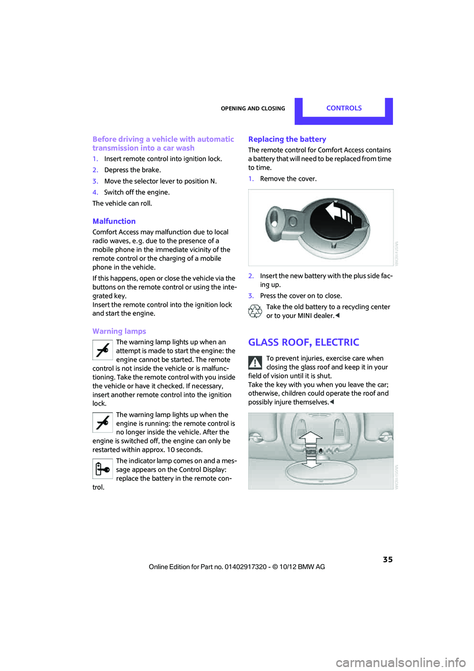
1. Remove the cover.
2. Insert the new battery with the plus side fac-
ing up.
3. Press the cover on to close.
Take the old battery to a recycling center
or to your MINI dealer. <
Glass roof, electric
To prevent injuries, exercise care when
closing the glass roof and keep it in your
field of vision until it is shut.
Take the key with you when you leave the car;
otherwise, children could operate the roof and
possibly injure themselves. <
00320051004F004C00510048000300280047004C0057004C005200510003
Page 48 of 267
DrivingCONTROLS
47
Driving
Vehicle equipment
In this chapter, all production, country, and
optional equipment that is offered in the model
range is described. Equipment is also described
that is not available because of, for example,
selected options or count ry version. This also
applies to safety related functions and systems.
Ignition lock
Inserting the key into the ignition lock
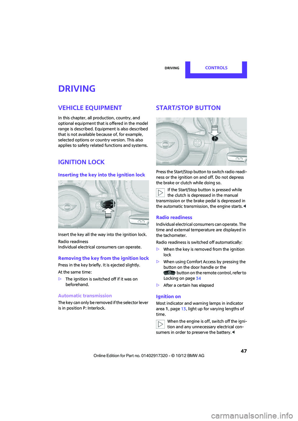
Insert the key all the way into the ignition lock.
Radio readiness
Individual electrical consumers can operate.
Removing the key from the ignition lock
Press in the key briefly. It is ejected slightly.
At the same time:
> The ignition is switched off if it was on
beforehand.
Automatic transmission
The key can only be removed if the selector lever
is in position P: Interlock.
Start/Stop button
Press the Start/Stop button to switch radio readi-
ness or the ignition on and off. Do not depress
the brake or clutch while doing so.
If the Start/Stop button is pressed while
the clutch is depressed in the manual
transmission or the brak e pedal is depressed in
the automatic transmission, the engine starts. <
Radio readiness
Individual electrical consumers can operate. The
time and external temperature are displayed in
the tachometer.
Radio readiness is switched off automatically:
>When the key is removed from the ignition
lock
> When using Comfort Access by pressing the
button on the door handle or the
button on the remote control, refer to
Locking on page 34
> After a certain has elapsed
Ignition on
Most indicator and warning lamps in indicator
area 1, page 13, light up for va rying lengths of
time.
When the engine is off, switch off the igni-
tion and any unnecessary electrical con-
sumers in order to preserve the battery. <
00320051004F004C00510048000300280047004C0057004C005200510003
Page 49 of 267
CONTROLSDriving
48
Radio readiness and ignition off
All indicator and warning lamps in the displays
go out.
The ignition switches off automatically if the
driver's door is opened. Pressing the Start/Stop
button again switches the ignition back on.
The ignition is not switched off in situations such
as the following:
> The clutch or brake is depressed
> The low beams are switched on
Starting the engine
Do not allow the engine to run in enclosed
areas; otherwise, inha lation of the noxious
exhaust gases can lead to loss of consciousness
and death. Exhaust gase s contain carbon mon-
oxide, an odorless and colorless, but highly toxic
gas. Never leave an unattended vehicle with the
engine running; otherwise, such a vehicle repre-
sents a potential safety hazard.
Before leaving the car while the engine is run-
ning, place the transmission in neutral or move
the selector lever to position P and forcefully
apply the parking brake to prevent the car from
moving. <
Avoid frequent starting in quick succes-
sion or repeated start attempts in which
the engine does not start. Otherwise, the fuel is
not burned or inadequate ly burned and there is
a danger of overheatin g and damaging the cat-
alytic converter. <
Do not let the engine warm up with the vehicle
at a standstill. Move off immediately at a moder-
ate engine speed.
When starting the engi ne, do not depress the
accelerator pedal.
Manual transmission
Key in ignition lock or inside vehicle with Com-
fort Access, refer to page 33.
1. Depress the brake.
2. Depress the clutch.
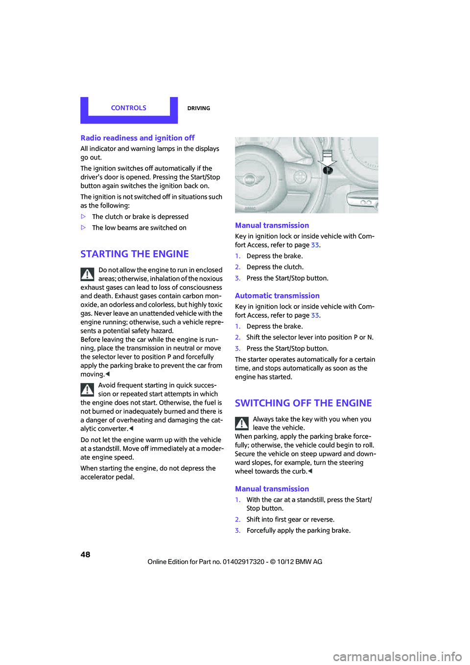
3. Press the Start/Stop button.
Automatic transmission
Key in ignition lock or inside vehicle with Com-
fort Access, refer to page 33.
1. Depress the brake.
2. Shift the selector lever into position P or N.
3. Press the Start/Stop button.
The starter operates auto matically for a certain
time, and stops automati cally as soon as the
engine has started.
Switching off the engine
Always take the key with you when you
leave the vehicle.
When parking, apply the parking brake force-
fully; otherwise, the vehicle could begin to roll.
Secure the vehicle on steep upward and down-
ward slopes, for example, turn the steering
wheel towards the curb. <
Manual transmission
1.With the car at a standstill, press the Start/
Stop button.
2. Shift into first gear or reverse.
3. Forcefully apply the parking brake.
00320051004F004C00510048000300280047004C0057004C005200510003
Page 50 of 267
DrivingCONTROLS
49
Automatic transmission
1.With the car at a stop, move the selector
lever to position P.
2. Press the Start/Stop button.
3. Forcefully apply the parking brake.
Before driving into a car wash
By following these steps, the vehicle is able to
roll:
1.Place the remote control, even with Comfort
Access, in the ig nition lock.
2. Depress the brake.
3. Move the selector lever to position N.
4. Switch off the engine.
Parking brake
The parking brake is primarily intended to pre-
vent the vehicle from rolling while parked; it
brakes the rear wheels.
In addition, follow the instructions on page 48
under Switching off the engine.
Applying
The lever locks in position automatically.
Releasing
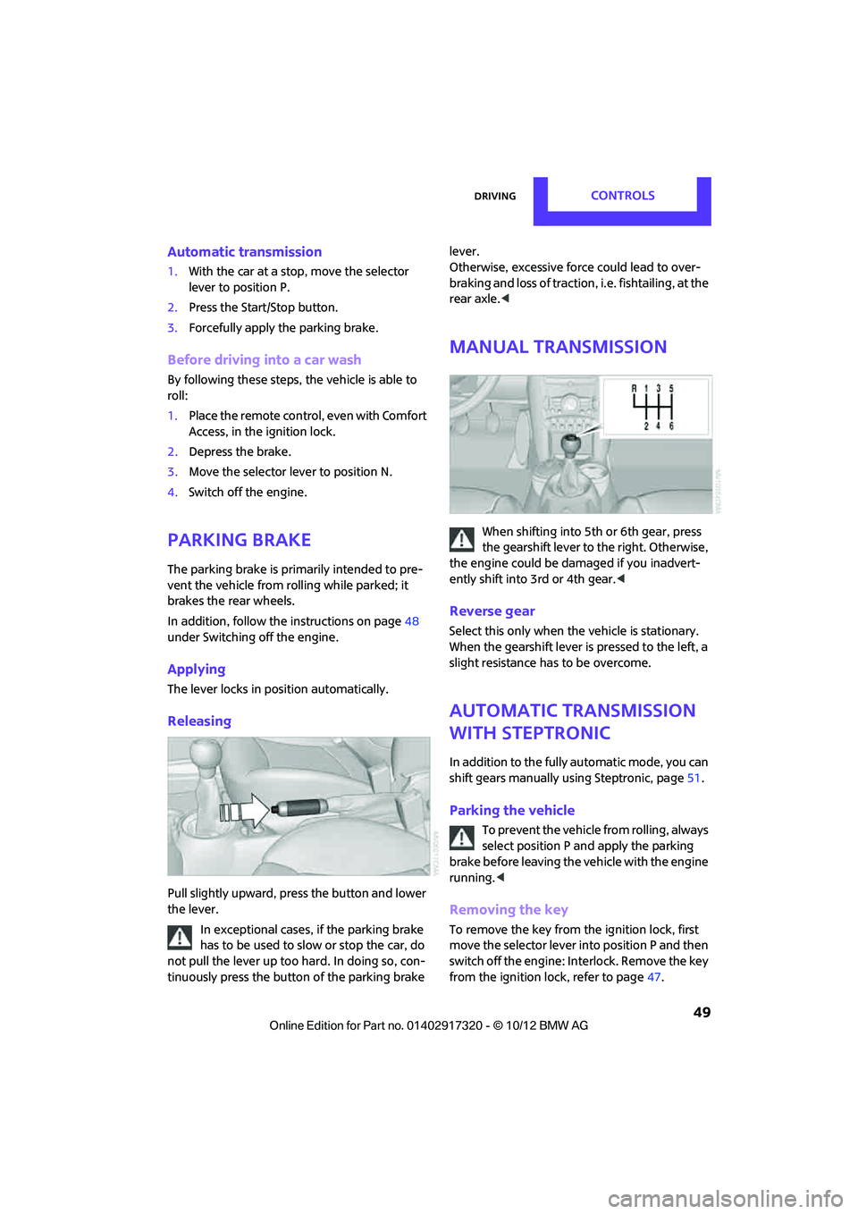
Pull slightly upward, pre ss the button and lower
the lever.
In exceptional cases, if the parking brake
has to be used to slow or stop the car, do
not pull the lever up too hard. In doing so, con-
tinuously press the button of the parking brake lever.
Otherwise, excessive force could lead to over-
braking and loss of traction, i.e. fishtailing, at the
rear axle.
<
Manual transmission
When shifting into 5th or 6th gear, press
the gearshift lever to the right. Otherwise,
the engine could be damaged if you inadvert-
ently shift into 3rd or 4th gear.<
Reverse gear
Select this only when the vehicle is stationary.
When the gearshift lever is pressed to the left, a
slight resistance ha s to be overcome.
Automatic transmission
with Steptronic
In addition to the fully automatic mode, you can
shift gears manually using Steptronic, page 51.
Parking the vehicle
To prevent the vehicle from rolling, always
select position P and apply the parking
brake before leaving the vehicle with the engine
running. <
Removing the key
To remove the key from the ignition lock, first
move the selector lever into position P and then
switch off the engine: Interlock. Remove the key
from the ignition lock, refer to page 47.
00320051004F004C00510048000300280047004C0057004C005200510003
Page 51 of 267
CONTROLSDriving
50
Selector lever positions
P R N D M/S + –
Displays in the tachometer
P R N D DS M1 to M6
The selector lever position is displayed, or the
current gear in the manual mode.
Changing selector lever positions
> The selector lever can only be moved out of
position P when the ignition is switched on
or the engine is running.
> Before moving the le ver away from P or N
with the vehicle stationary, first depress the
brake; otherwise, the selector lever will
refuse to move: Shiftlock.
To prevent the vehicle from creeping
after you select a driving position,
depress the brake until you are ready to
start. <
A lock prevents accidental shifting into selector
lever positions R and P.
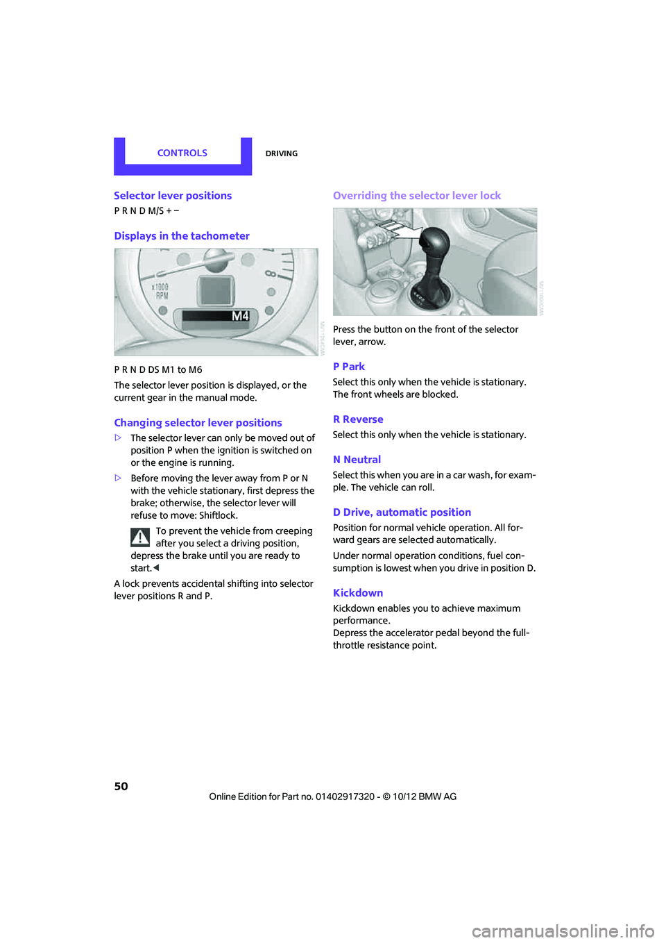
Overriding the selector lever lock
Press the button on the front of the selector
lever, arrow.
P Park
Select this only when the vehicle is stationary.
The front wheels are blocked.
R Reverse
Select this only when the vehicle is stationary.
N Neutral
Select this when you are in a car wash, for exam-
ple. The vehicle can roll.
D Drive, automatic position
Position for normal vehi cle operation. All for-
ward gears are selected automatically.
Under normal operation conditions, fuel con-
sumption is lowest when you drive in position D.
Kickdown
Kickdown enables you to achieve maximum
performance.
Depress the accelerator pedal beyond the full-
throttle resistance point.
00320051004F004C00510048000300280047004C0057004C005200510003