roof MINI COOPER 2014 User Guide
[x] Cancel search | Manufacturer: MINI, Model Year: 2014, Model line: COOPER, Model: MINI COOPER 2014Pages: 230, PDF Size: 11.58 MB
Page 152 of 230

Load
The maximum load is the sum of the weight of
the occupants and the cargo.
The greater the weight of the occupants, the
less cargo that can be transported.
Stowing cargo
▷Cover sharp edges and corners on the
cargo.▷Heavy cargo: stow as far forward as possi‐
ble, directly behind and at the bottom of
the rear passenger seat backrests.▷Very heavy cargo: when the rear seat is not
occupied, secure each of the outer safety
belts in the opposite buckle.▷If necessary, fold down the rear backrests
to stow cargo.▷Do not stack cargo above the top edge of
the backrests.Securing cargo
Lashing eyes in the cargo area
Without storage compartment package: to se‐
cure the cargo there are two lashing eyes, ar‐
row 1, in the cargo area.
With storage compartment package: to secure
the cargo there are six lashing eyes, arrows 1
and 2, in the cargo area.
Securing cargo
▷Smaller and lighter items: secure with re‐
taining straps or with draw straps.▷Larger and heavy objects: secure with
cargo straps.
Attach the cargo straps, retaining straps or
draw straps to the lashing eyes in the cargo
area.
Securing cargo
Stow and secure the cargo as described
above; otherwise it may present a danger to
the occupants, e.g., during braking and avoid‐
ance maneuvers. ◀
Roof-mounted luggage
rack
Note Installation only possible with roof rack.
Roof racks are available as special accessories.
Seite 152DRIVING TIPSLoading152
Online Edition for Part no. 01 40 2 927 905 - II/14
Page 153 of 230
Securing
Follow the installation instructions of the roof
rack.
Loading Be sure that adequate clearance is maintained
for tilting and opening the glass sunroof.
Because roof racks raise the vehicle's center of
gravity when loaded, they have a major effect
on vehicle handling and steering response.
Therefore, note the following when loading and
driving:▷Do not exceed the approved roof/axle
loads and the approved gross vehicle
weight.▷Distribute the roof load uniformly.▷The roof load should not be too large in
area.▷Always place the heaviest pieces on the
bottom.▷Secure the roof luggage firmly, e.g., tie with
ratchet straps.▷Do not let objects project into the opening
path of the tailgate.▷Drive cautiously and avoid sudden acceler‐
ation and braking maneuvers. Take corners
gently.
Rear luggage rack
General information Installation only possible with rear luggage rack
preparation.
Rear racks are available as special accessories.
Note Follow the installation instructions of the rear
luggage rack.
Drive cautiously and avoid sudden acceleration
and braking maneuvers. Take corners gently.
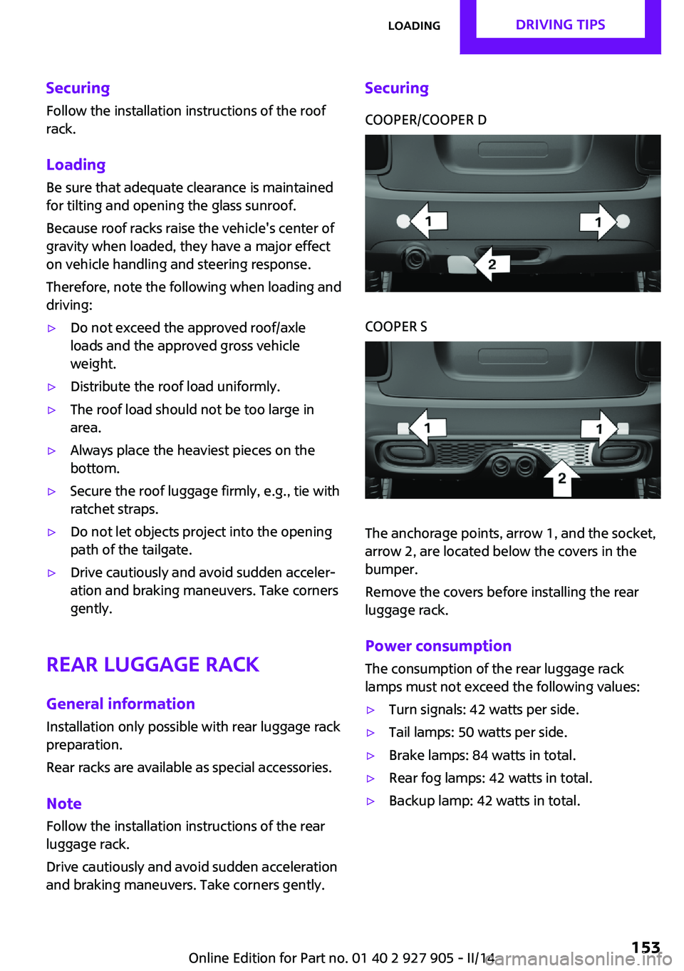
SecuringCOOPER/COOPER DCOOPER S
The anchorage points, arrow 1, and the socket,
arrow 2, are located below the covers in the
bumper.
Remove the covers before installing the rear
luggage rack.
Power consumption
The consumption of the rear luggage rack
lamps must not exceed the following values:
▷Turn signals: 42 watts per side.▷Tail lamps: 50 watts per side.▷Brake lamps: 84 watts in total.▷Rear fog lamps: 42 watts in total.▷Backup lamp: 42 watts in total.Seite 153LoadingDRIVING TIPS153
Online Edition for Part no. 01 40 2 927 905 - II/14
Page 155 of 230

Saving fuelVehicle equipment
All standard, country-specific and optional
equipment that is offered in the model series is
described in this chapter. Therefore, equipment
is also described that is not available in a vehi‐
cle, e. g., because of the selected optional
equipment or country variant. This also applies
for safety-related functions and systems.
General information
Fuel consumption depends on a number of dif‐
ferent factors.
The implementation of certain measures, driv‐
ing style and regular maintenance can have an
influence on fuel consumption and on the envi‐
ronmental impact.
Remove unnecessary
cargo
Additional weight increases fuel consumption.
Remove attached partsfollowing use
Remove roof or rear luggage racks which are
no longer required following use.
Attached parts on the vehicle impair the aero‐
dynamics and increase the fuel consumption.
Close the windows andglass sunroof
Driving with the glass sunroof and windows
open results in increased air resistance and
raises fuel consumption.Tires
General information Tires can affect fuel consumption values in vari‐
ous ways, for instance fuel consumption can be
influenced by the size of the tires.
Check the tire inflation pressure
regularly
Check and, if necessary, correct the tire infla‐
tion pressure at least twice a month and before
starting on a long trip.
Low tire inflation pressure increases rolling re‐
sistance and thus raises fuel consumption and
tire wear.
Drive away without de‐lay
Do not wait for the engine to warm-up while
the vehicle remains stationary. Start driving right away, but at moderate engine speeds.
This is the fastest way for the cold engine to
reach its operating temperature.
Look well ahead when
driving
Avoid unnecessary acceleration and braking.
By maintaining a suitable distance to the vehi‐
cle driving ahead of you.
Driving smoothly and looking ahead reduces
fuel consumption.Seite 155Saving fuelDRIVING TIPS155
Online Edition for Part no. 01 40 2 927 905 - II/14
Page 160 of 230

Display
Display in the instrument cluster The mark in the bar display be‐
low the tachometer is high‐
lighted green and appears at the
zero point. The tachometer ap‐
proximately indicates idle speed.
Indications on the Control Display
The Coasting driving condition is displayed in
MINIMALISM Info while this driving mode is ac‐
tive.
The distance traveled in the Coasting driving
condition is indicated by a counter.
Color code green, arrow 1: distance traveled in
the Coasting driving condition. Symbol, ar‐
row 2: coasting driving condition.
Displaying MINIMALISM info
1. "Vehicle Info"2."MINIMALISM"3. "MINIMALISM info"
Deactivating the system manually The function can be deactivated in the Config‐
ure GREEN mode, refer to page 157, menu,
e.g., to use the braking effect of the engine
when traveling downhill.
The setting is saved for the profile currently be‐
ing used.
MINIMALISM driving style analysis
The concept
The system helps in this situation to develop an
especially efficient driving style and to conserve
fuel.
For this purpose, the driving style is analyzed.
The assessment is done in various categories
and is displayed on the Control Display.
Using this indication, the individual driving style
can be oriented toward conserving fuel.
The last fifteen minutes of a trip are evaluated.
The range of the vehicle can be extended by an
efficient driving style. This gain in range is dis‐
played as a bonus range in the instrument clus‐
ter and on the Control Display.
Functional requirement
The function is only available in GREEN mode.
Calling up MINIMALISM Analyser Via the Driving Dynamics Control1.Activate GREEN mode.2."MINIMALISM"3. Select the symbol.
Display
Display on the Control Display
The display of the MINIMALISM Analyser con‐
sists of a fish, which is riding along in a glass of
water on the roof of the MINI and a table of
values that rates the driving style in various cat‐
Seite 160DRIVING TIPSSaving fuel160
Online Edition for Part no. 01 40 2 927 905 - II/14
Page 186 of 230

MaintenanceVehicle equipment
All standard, country-specific and optional
equipment that is offered in the model series is
described in this chapter. Therefore, equipment
is also described that is not available in a vehi‐
cle, e. g., because of the selected optional
equipment or country variant. This also applies
for safety-related functions and systems.
MINI maintenance system
The maintenance system indicates required
maintenance measures, and thereby provides
support in maintaining road safety and the op‐
erational reliability of the vehicle.
Condition Based Service
CBS
Sensors and special algorithms take into ac‐
count the driving conditions of your vehicle.
Based on this, Condition Based Service deter‐
mines the maintenance requirements.
The system makes it possible to adapt the
amount of maintenance you need to your user
profile.
Detailed information on service requirements,
refer to page 76, can be displayed on the Con‐
trol Display.
Service data in the remote control
Information on the required maintenance is
continuously stored in the remote control. Your
service center will read out this data and sug‐
gest the right array of service procedures for
your vehicle.
Therefore, hand your service specialist the re‐
mote control that you used most recently.Storage periods
Storage periods during which the vehicle bat‐
tery was disconnected are not taken into ac‐
count.
If this occurs, have a service center update the
time-dependent maintenance procedures, such
as checking brake fluid and, if necessary,
changing the engine oil and the microfilter/acti‐
vated-charcoal filter.
Service and Warranty In‐
formation Booklet for
US models and Warranty
and Service Guide Book‐
let for Canadian models
Please consult your Service and Warranty Infor‐
mation Booklet for US models and Warranty
and Service Guide Booklet for Canadian models
for additional information on service require‐
ments.
Maintenance and repair should be performed
by your service center. Make sure to have regu‐
lar maintenance procedures recorded in the ve‐
hicle's Service and Warranty Information Book‐
let for US models, and in the Warranty and
Service Guide Booklet for Canadian models.
These entries are proof of regular maintenance.
Socket for OBD Onboard
Diagnosis
Note Socket for Onboard Diagnosis
The socket for onboard diagnostics may
only be used by the service center or a work‐ shop that operates in accordance with theSeite 186MOBILITYMaintenance186
Online Edition for Part no. 01 40 2 927 905 - II/14
Page 207 of 230

CareVehicle equipmentAll standard, country-specific and optional
equipment that is offered in the model series is
described in this chapter. Therefore, equipment
is also described that is not available in a vehi‐
cle, e. g., because of the selected optional
equipment or country variant. This also applies
for safety-related functions and systems.
Car washes
Hints Steam jets or high-pressure washers
When using steam jets or high-pressure
washers, hold them a sufficient distance away
and use a maximum temperature of
140 ℉/60 ℃.
If the vehicle has a glass sunroof, ensure that a
distance of at least 31.5 inches/80 cm is main‐
tained. Holding them too close or using exces‐
sively high pressures or temperatures can
cause damage or preliminary damage that may
then lead to long-term damage.
Follow the user's manual for the high-pressure
washer. ◀
Cleaning sensors/cameras with high-pres‐
sure washers
When using high-pressure washers, do not
spray the exterior sensors and cameras, e.g.,
Park Distance Control, for extended periods of
time and only from a distance of at least
12 in/30 cm. ◀▷Regularly remove foreign items such as
leaves in the area below the windshield
when the hood is raised.▷Wash your vehicle frequently, particularly in
winter.Intense soiling and road salt can damage
the vehicle.
Automatic car washes
Hints
▷Give preference to cloth car washes or
those that use soft brushes in order to
avoid paint damage.▷Make sure that the wheels and tires are not
damaged by the transport mechanisms.▷Fold in the exterior mirrors; otherwise, they
may be damaged, depending on the width
of the vehicle.▷Unscrew the rod antenna.▷Deactivate the rain sensor, refer to
page 65, to avoid unintentional wiper acti‐
vation.▷In some cases, an unintentional alarm can
be triggered by the interior motion sensor
of the alarm system. Follow the instructions
on avoiding an unintentional alarm, refer to
page 43.
Guide rails in car washes
Avoid car washes with guide rails higher
than 4 in/10 cm; otherwise, the vehicle body
could be damaged. ◀
Before driving into a car wash In order to ensure that the vehicle can roll in a
car wash, take the following steps:
Manual transmission:
1.Drive into the car wash.2.Shift to neutral.3.Switch the engine off.4.Switch on the ignition.Seite 207CareMOBILITY207
Online Edition for Part no. 01 40 2 927 905 - II/14
Page 214 of 230

Technical dataVehicle equipment
All standard, country-specific and optional
equipment that is offered in the model series is
described in this chapter. Therefore, equipmentis also described that is not available in a vehi‐
cle, e. g., because of the selected optional
equipment or country variant. This also applies
for safety-related functions and systems.
Dimensions
MINIWidth with mirrorsinches/mm76.1/1932Width without mirrorsinches/mm68.0/1727Height with roof antennainches/mm55.7/1414Lengthinches/mm151.1/3837Cooper S: lengthinches/mm151.9/3858Wheelbaseinches/mm98.2/2495Smallest turning circle diam.ft/m35/10.8
Weights
The values preceding the slash apply to vehicles
with manual transmission; the values followingthe slash apply to vehicles with automatic
transmission. MINI CooperCurb weight, road ready, with 75 kg load, with fuel
tank 90 % full, without special equipmentlbs
kg2605/2675
1182/1213Approved gross vehicle weightlbs
kg3455/3520
1567/1597Loadlbs
kg680
305Approved front axle loadlbs
kg1905/1975
864/896Seite 214REFERENCETechnical data214
Online Edition for Part no. 01 40 2 927 905 - II/14
Page 215 of 230

MINI CooperApproved rear axle loadlbs
kg1665/1665
755/755Approved roof load capacitylbs
kg60
60Cargo area capacitycu ft/l8.7/211
MINI Cooper SCurb weight, road ready, with 75 kg load, with fuel
tank 90 % full, without special equipmentlbs
kg2760/2795
1252/1268Approved gross vehicle weightlbs
kg3620/3650
1642/1656Loadlbs
kg770/775
349/352Approved front axle loadlbs
kg2010/2045
912/928Approved rear axle loadlbs
kg1690/1690
767/767Approved roof load capacitylbs
kg60
60Cargo area capacitycu ft/l8.7/211
Capacities
MINICooper: fuel tankUS gal/liters10.5/40Fuel tankUS gal/liters11.6/44Seite 215Technical dataREFERENCE215
Online Edition for Part no. 01 40 2 927 905 - II/14
Page 223 of 230

Front fog lamps 89
Front passenger airbags, auto‐ matic deactivation 93
Front passenger airbags, indi‐ cator lamp 93
FTM Flat Tire Monitor 97
Fuel 166
Fuel cap 164
Fuel consumption, current 75
Fuel consumption, refer to Average fuel consump‐
tion 79
Fuel filler flap 164
Fuel gauge 74
Fuel quality 166
Fuel recommendation 166
Fuel, tank capacity 215
Fuse 199
G Garage door opener, refer to Universal garage door
opener 133
Gasoline 166
Gear change, automatic trans‐ mission 68
Gear shift indicator 76
General driving notes 148
Glass sunroof, refer to Panor‐ amic glass sunroof 45
Glove compartment 141
GREEN mode 156
GREEN mode, bonus range 158
GREEN mode driving style analysis 160
GREEN mode indicator 156
GREEN - program, driving dy‐ namics 108
GREEN tip 158
Gross vehicle weight, ap‐ proved 214
Ground clearance 150 H
Halogen headlamps 190
Handbrake, refer to parking brake 63
Hand-held transmitter, alter‐ nating code 134
Hazard warning flashers 201
Head airbags 91
Headlamp control, auto‐ matic 87
Headlamp courtesy delay fea‐ ture 87
Headlamp flasher 64
Headlamp glass 189
Headlamps, care 208
Headlamp washer system 64
Headliner 17
Head restraints 47
Head restraints, front 50
Head restraints, rear 51
Head-up Display 83
Head-up Display, standard view 84
Heavy cargo, stowing 152
High-beam Assistant 88
High beams 64
High beams/low beams, refer to High-beam Assistant 88
Hills 150
Hill start assistant, refer to Drive-off assistant 109
Hints 6
Holder for beverages 142
Homepage 6
Hood 180
Horn 14
Hot exhaust system 149
HUD Head-up Display 83
Hydroplaning 149
I
Ice warning, see External tem‐ perature warning 75 Icy roads, see External tem‐
perature warning 75
Identification marks, tires 171
Identification number, refer to Important features in the en‐
gine compartment 180
Ignition key, refer to Remote control 34
Ignition off 59
Ignition on 59
Illuminated ring, central in‐ strument cluster 82
Indication of a flat tire 95, 98
Individual air distribu‐ tion 128, 130
Individual settings, refer to Personal Profile 35
Inflation pressure, tires 168
Inflation pressure warning, tires 97
Info display, refer to Com‐ puter 79
Initialize, Tire Pressure Moni‐ tor TPM 95
Initializing, Flat Tire Monitor FTM 98
Instrument cluster 71
Instrument cluster, electronic displays 72
Instrument lighting 89
Integrated key 34
Intelligent Emergency Re‐ quest 201
Intelligent Safety 99
Intensity, AUTO program 130
Interior equipment 133
Interior lamps 89
Interior lamps via remote con‐ trol 37
Interior motion sensor 43
Interior rearview mirror, auto‐ matic dimming feature 53
Interior rearview mirror, com‐ pass 135
Interior rearview mirror, man‐ ually dimmable 53 Seite 223Everything from A to ZREFERENCE223
Online Edition for Part no. 01 40 2 927 905 - II/14
Page 224 of 230

Internet site 6
Interval display, service re‐ quirements 76
J
Jacking points for the vehicle jack 196
Joystick, automatic transmis‐ sion 68
Jump-starting 202
K Key/remote control 34
Keyless Go, refer to Comfort Access 40
Key Memory, refer to Personal Profile 35
Kickdown, automatic trans‐ mission 68
Knee airbag 91
L Lamp replacement 189
Lamp replacement, front 190
Lamp replacement, rear 192
Lamp replacement, side 195
Lamps and bulbs 189
Language on Control Dis‐ play 82
Lashing eyes, securing cargo 152
LATCH child restraint fixing system 56
Launch Control 70
Leather, care 208
LED bug light 190
LED headlamps 190
LED ring, central instrument cluster 82
LEDs, light-emitting di‐ odes 189
Left-hand traffic, lamp set‐ ting 89 Letters and numbers, enter‐
ing 24
Light 86
Light-alloy wheels, care 209
Light-emitting diodes, LEDs 189
Lighter 138
Lighting 86
Lighting via remote con‐ trol 37
Light switch 86
Load 152
Loading 151
Lock, door 38
Locking/unlocking via door lock 38
Locking/unlocking with re‐ mote control 37
Locking, automatic 42
Locking, settings 42
Low beams 86
Low beams, automatic, refer to High-beam Assistant 88
Lower back support, mechani‐ cal 48
Lug bolt lock 198
Luggage rack, refer to Roof- mounted luggage rack 152
Lumbar support, mechani‐ cal 48
M
Maintenance 186
Maintenance require‐ ments 186
Maintenance, service require‐ ments 76
Maintenance system, MINI 186
Malfunction displays, refer to Check Control 72
Manual air distribu‐ tion 128, 130
Manual air flow 128, 130 Manual mode, transmis‐
sion 68
Manual operation, door lock 38
Manual operation, exterior mirrors 52
Manual operation, fuel filler flap 164
Manual operation, Park Dis‐ tance Control PDC 119
Manual operation, rearview camera 121
Manual transmission 67
Manufacturer of the MINI 7
Marking on approved tires 174
Marking, run-flat tires 175
Master key, refer to Remote control 34
Maximum cooling 130
Maximum speed, display 77
Maximum speed, winter tires 174
Measure, units of 82
Medical kit 202
Menu in instrument cluster 78
Menus, refer to onboard mon‐ itor operating concept 20
Microfilter 129, 132
MID - program, driving dy‐ namics 108
MINI Connected, refer to Integrated Owner's Manual
MINI maintenance sys‐ tem 186
MINIMALISM Analyser 160
MINIMALISM info 159
Minimum tread, tires 172
Mirrors 52
Mobile communication devi‐ ces in the vehicle 149
Mobility System 175
Mode, GREEN Mode 156
Modifications, technical, refer to Safety 7
Moisture in headlamp 189 Seite 224REFERENCEEverything from A to Z224
Online Edition for Part no. 01 40 2 927 905 - II/14