tailgate MINI COOPER 2014 User Guide
[x] Cancel search | Manufacturer: MINI, Model Year: 2014, Model line: COOPER, Model: MINI COOPER 2014Pages: 230, PDF Size: 11.58 MB
Page 138 of 230

At a glance
The USB interface is located in the front of the
center console.
Hints Observe the following when connecting:
▷Do not use force when plugging the con‐
nector into the USB interface.▷Do not connect devices such as fans or
lamps to the USB interface.▷Do not connect any USB hard drives or USB
hubs.▷Do not use the USB interface to recharge
external devices.
Ashtray/cigarette
lighter
At a glance
The ashtray is located in one of the front cu‐
pholders, the cigarette lighter above it in the
center console.
Ashtray
In order to empty the ashtray, remove the ash‐
tray from the cupholder.
Lighter Danger of burns
Only hold the hot lighter by its knob; oth‐
erwise, there is the danger of getting burned.
Switch off the ignition and take the remote
control with you when leaving the vehicle so
that children cannot use the lighter and burn
themselves. ◀
Replace the cover after use
Reinsert the lighter or socket cover after
use, otherwise objects may get into the lighter
socket or fixture and cause a short circuit. ◀
Push in the lighter.
The lighter can be removed as
soon as it pops back out.
Cargo area Cargo cover
When the tailgate is opened, the cargo cover is
raised.
Do not deposit heavy objects
Do not deposit heavy or hard objects on
the cargo cover. Otherwise, they may pose a
risk to occupants, such as during braking and
avoidance maneuvers. ◀
To stow bulky objects, the cargo cover can be
removed:
Removing cargo cover1.Detach the left and right retaining straps at
the tailgate.Seite 138CONTROLSInterior equipment138
Online Edition for Part no. 01 40 2 927 905 - II/14
Page 139 of 230

2.Pull the cargo cover out of the brackets on
the left and right.
Installing cargo cover
1.Slide the cover forward horizontally into the
two side brackets until it audibly latches.2.Attach the left and right retaining straps at
the tailgate.
Enlarging the cargo area
General information
The cargo area can be enlarged by folding
down the rear seat backrest.
The rear seat backrest is divided into two parts
at a ratio of 60 to 40. The backrest of the right
seat is connected to the backrest center sec‐
tion.
Hints Danger of pinching
Before folding down the rear seat back‐
rests, ensure that the area of movement of the
backrests is clear. Ensure that no one is located
in or reaches into the area of movement of the
rear seat backrests. Otherwise, injury or dam‐
age may result. ◀
Push the headrests down, before the
backrests are folded down
Before folding down the rear seat backrests,
make sure that the corresponding headrest is
pushed all the way down; otherwise, damage
may result. ◀
Folding down rear seat backrest
The rear seat backrests can be folded down
from the front or from the cargo area.
Before the backrest is folded down, hook the
corresponding safety belt into the safety belt
on the side.
Pull the release upward and fold the backrest
toward the front.
Folding back the backrest Ensure that the lock is securely engaged
When folding back the backrest, make
sure that it securely locks in place. When this
happens the red warning field on the seat dis‐
appears. If the backrest is not properly en‐
gaged, transported cargo could enter the pas‐
senger compartment during braking or evasive
maneuvers and endanger the vehicle occu‐
pants. ◀
Fold up the backrest and press it into the latch.
Make sure that the safety belt is not pinched.
Adjusting the backrest tilt To transport bulky items, the cargo area can be
expanded by setting the backrests at a steeper
angle.
1.Released the back rest, and tilt it forward.Seite 139Interior equipmentCONTROLS139
Online Edition for Part no. 01 40 2 927 905 - II/14
Page 148 of 230

Things to remember when drivingVehicle equipmentAll standard, country-specific and optional
equipment that is offered in the model series is
described in this chapter. Therefore, equipment
is also described that is not available in a vehi‐
cle, e. g., because of the selected optional
equipment or country variant. This also applies
for safety-related functions and systems.
Breaking-in period General information
Moving parts need to be broken in to adjust to
each other.
The following instructions will help achieve a
long vehicle life and good economy.
Engine and axle drive
Always obey the official speed limit.
Up to 1,200 miles/2,000 km Do not exceed the maximum engine and road
speed:▷For gasoline engine, 4,500 rpm and
100 mph/160 km/h.▷For diesel engine, 3,500 rpm and
93 mph/150 km/h.
Avoid full load or kickdown under all circum‐
stances.
From 1,200 miles/2,000 km
The engine and vehicle speed can gradually be
increased.
Tires Due to technical factors associated with their
manufacture, tires do not achieve their full trac‐
tion potential until after an initial breaking-in
period.
Drive conservatively for the first
200 miles/300 km.
Brake system Brakes require an initial break-in period of ap‐
prox. 300 miles/500 km to achieve optimized
contact and wear patterns between brake discs
and brake pads. Drive moderately during this
break-in period.
Clutch
The function of the clutch reaches its optimal
level only after a distance driven of approx.
300 miles/500 km. During this break-in period,
engage the clutch gently.
Following part replacement The same breaking in procedures should be ob‐
served if any of the components mentioned
above have to be renewed in the course of the
vehicle's operating life.
General driving notes
Closing the tailgate Drive with the tailgate closed
Only drive with the tailgate closed; other‐
wise, in the event of an accident or braking and
evasive maneuvers, passengers and other road
users may be injured, and the vehicle may be
damaged. In addition, exhaust fumes may en‐
ter the passenger compartment. ◀
If driving with the tailgate open cannot be
avoided:▷Close all windows and the glass sunroof.▷Greatly increase the blower speed.Seite 148DRIVING TIPSThings to remember when driving148
Online Edition for Part no. 01 40 2 927 905 - II/14
Page 153 of 230
Securing
Follow the installation instructions of the roof
rack.
Loading Be sure that adequate clearance is maintained
for tilting and opening the glass sunroof.
Because roof racks raise the vehicle's center of
gravity when loaded, they have a major effect
on vehicle handling and steering response.
Therefore, note the following when loading and
driving:▷Do not exceed the approved roof/axle
loads and the approved gross vehicle
weight.▷Distribute the roof load uniformly.▷The roof load should not be too large in
area.▷Always place the heaviest pieces on the
bottom.▷Secure the roof luggage firmly, e.g., tie with
ratchet straps.▷Do not let objects project into the opening
path of the tailgate.▷Drive cautiously and avoid sudden acceler‐
ation and braking maneuvers. Take corners
gently.
Rear luggage rack
General information Installation only possible with rear luggage rack
preparation.
Rear racks are available as special accessories.
Note Follow the installation instructions of the rear
luggage rack.
Drive cautiously and avoid sudden acceleration
and braking maneuvers. Take corners gently.
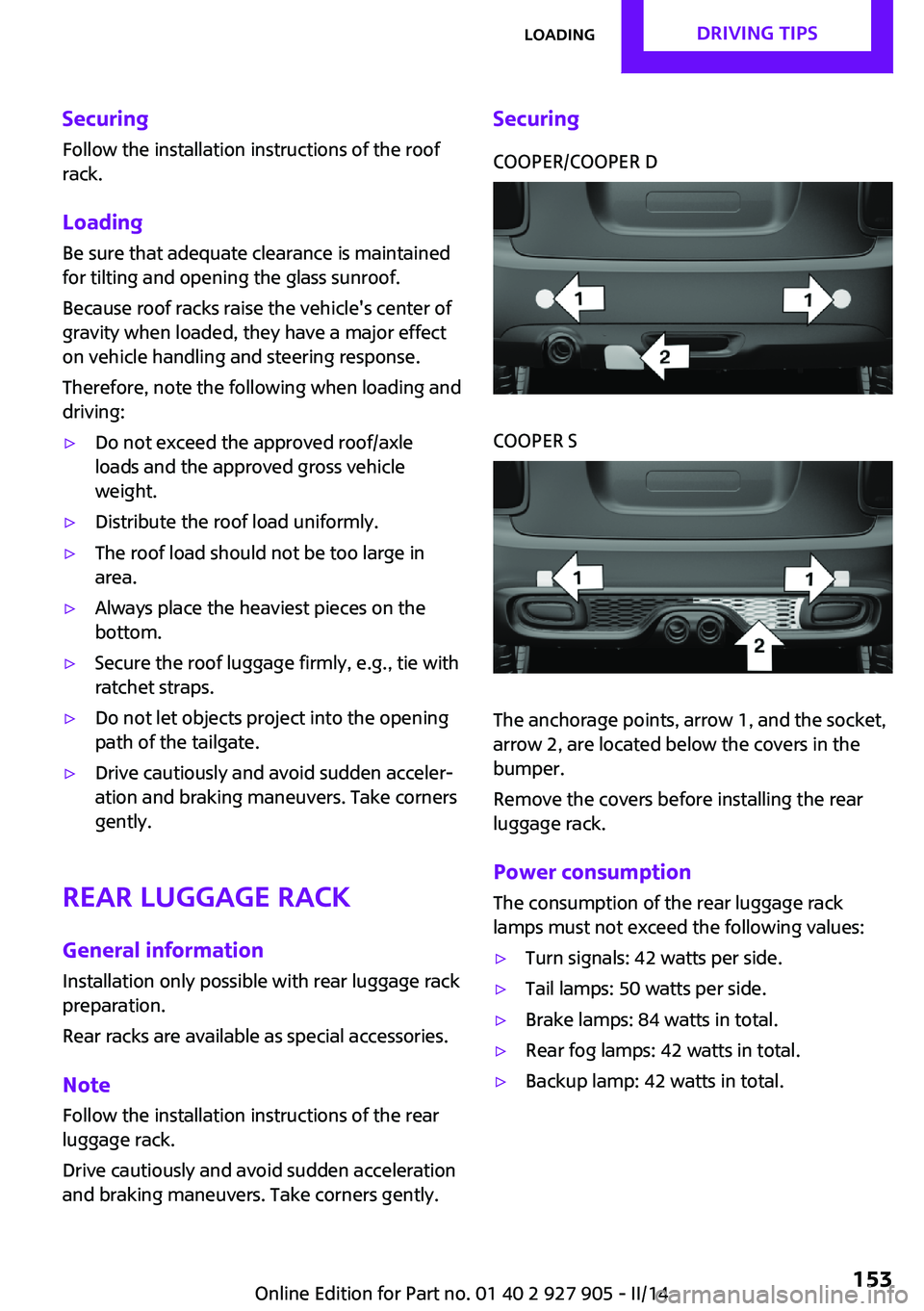
SecuringCOOPER/COOPER DCOOPER S
The anchorage points, arrow 1, and the socket,
arrow 2, are located below the covers in the
bumper.
Remove the covers before installing the rear
luggage rack.
Power consumption
The consumption of the rear luggage rack
lamps must not exceed the following values:
▷Turn signals: 42 watts per side.▷Tail lamps: 50 watts per side.▷Brake lamps: 84 watts in total.▷Rear fog lamps: 42 watts in total.▷Backup lamp: 42 watts in total.Seite 153LoadingDRIVING TIPS153
Online Edition for Part no. 01 40 2 927 905 - II/14
Page 188 of 230

Replacing componentsVehicle equipmentAll standard, country-specific and optional
equipment that is offered in the model series is
described in this chapter. Therefore, equipment
is also described that is not available in a vehi‐
cle, e. g., because of the selected optional
equipment or country variant. This also applies
for safety-related functions and systems.
Onboard vehicle tool kit
The onboard vehicle tool kit is located in the
trough under the cargo area floor.
The warning triangle is located in the tailgate
trim.
Wiper blade replacement
Note Do not fold down the wipers without
wiper blades
Do not fold down the wipers if wiper blades
have not been installed; this may damage the
windshield. ◀
Replacing the wiper blades1.Fold up and hold the wiper arm firmly.2.Open the wiper blade lock, arrow.3.Pull the wiper blade first downward out of
the holder on the wiper arm, arrow 1.
Then pull the wiper blade free from the
holder of the wiper arm, arrow 2.4.Insert and latch a new wiper blade in re‐
verse order.5.Fold down the wipers.
Folding down wipers before opening the
hood
Before opening the hood, ensure that the wiper
arms with the wiper blades are against the
windshield to prevent damage. ◀
Seite 188MOBILITYReplacing components188
Online Edition for Part no. 01 40 2 927 905 - II/14
Page 193 of 230

Vehicle with two rear fog lamps1Side tail lamps2Rear fog lamps3License plate lamp4High brake lights
Side tail lamps
1Brake lights/tail lights2Turn signal3Reversing lightsSide LED tail lamps1Brake lights/tail lights2Turn signal3Reversing lights
Side tail lampsFollow the general instructions on lamps and
bulbs, refer to page 189.
Bulbs: P21W
1.Open the tailgate., refer to page 392.Remove left or right cover.3.Through the opening, loosen the plug con‐
nector, arrow 2 on the bulb holder.Seite 193Replacing componentsMOBILITY193
Online Edition for Part no. 01 40 2 927 905 - II/14
Page 202 of 230

▷If the LED is flashing but the MINI Response
Center cannot be heard on the speaker, the
hands-free system may be malfunctioning.
However, the MINI Response Center may
still be able to hear you.
Initiating an Emergency Request
automatically
Under certain conditions, an Emergency Re‐
quest is automatically initiated immediately af‐
ter a severe accident. Automatic Collision Noti‐
fication is not affected by pressing the SOS
button.
Warning triangle
The warning triangle is located in the tailgate.
To remove, loosen the brackets.
First aid kit
The first aid kit is located in the cargo area.
Some of the articles have a limited service life.
Check the expiration dates of the contents reg‐
ularly and replace any expired items promptly.
Roadside Assistance
Service availability Roadside Assistance can be reached around the
clock in many countries. You can obtain assis‐
tance there in the event of a vehicle break‐
down.
Jump-starting
Hints If the battery is discharged, an engine can be
started using the battery of another vehicle and
two jumper cables. Only use jumper cables with
fully insulated clamp handles.
To prevent personal injury or damage to both
vehicles, adhere strictly to the following proce‐
dure.
Do not touch live parts
To avoid the risk of potentially fatal injury,
always avoid all contact with electrical compo‐
nents while the engine is running. ◀
Preparation1.Check whether the battery of the other ve‐
hicle has a voltage of 12 volts. This informa‐
tion can be found on the battery.2.Switch off the engine of the assisting vehi‐
cle.3.Switch off any electronic systems/power
consumers in both vehicles.
Bodywork contact between vehicles
Make sure that there is no contact be‐
tween the bodywork of the two vehicles; other‐
wise, there is the danger of short circuits. ◀
Starting aid terminals Connecting order
Connect the jumper cables in the correct
order; otherwise, there is the danger of injury
from sparking. ◀
Seite 202MOBILITYBreakdown assistance202
Online Edition for Part no. 01 40 2 927 905 - II/14
Page 227 of 230

Symbols in the status field 23
T Tachometer 74
Tailgate 39
Tailgate via remote control 38
Tail lamps 192
Technical changes, refer to Safety 7
Technical data 214
Temperature, air condi‐ tioner 128
Temperature, automatic cli‐ mate control 130
Temperature display for exter‐ nal temperature 75
Temperature, engine oil 74
Terminal, starting aid 202
Text messages, supplemen‐ tary 73
Theft alarm system, refer to Alarm system 42
Theft protection, lug bolts 198
Thigh support 48
Tilt alarm sensor 43
Time of arrival 80
Tire damage 173
Tire identification marks 171
Tire inflation pressure 168
Tire inflation pressure moni‐ tor, refer to FTM 97
Tire Pressure Monitor TPM 94
Tires, changing 173
Tire sealant 175
Tires, everything on wheels and tires 168
Tires, run-flat tires 175
Tire tread 172
Tone, refer to Integrated Owner's Manual
Tools 188
Total vehicle weight 214
Touchpad 21 Tourist function, refer to
Right-hand/left-hand traf‐
fic 89
Tow fitting 205
Towing 203
Tow-starting 203
TPM Tire Pressure Monitor 94
Traction control 107
TRACTION drive mode, driving dynamics 107
Transmission, automatic 67
Transmission lock, releasing manually 69
Transmission, manual 67
Transporting children safely 55
Tread, tires 172
Trip computer 80
Triple turn signal activa‐ tion 64
Trip odometer 74
Turning circle lines, rearview camera 121
Turn signal, front 190
Turn signal, side 195
Turn signals, operation 64
Turn signals, rear, bulb re‐ placement 192
U
Unintentional alarm 43
Units of measure 82
Universal remote control 133
Unlock button, automatic transmission 68
Unlocking/locking via door lock 38
Unlocking/locking with re‐ mote control 37
Unlocking, settings 42
Updates made after the edito‐ rial deadline 6
Upholstery care 209
USB interface 137 V
Vehicle battery 198
Vehicle battery, replacing 199
Vehicle, breaking in 148
Vehicle care 208
Vehicle equipment 6
Vehicle identification number, refer to Identification num‐
ber in the engine compart‐
ment 180
Vehicle jack 196
Vehicle paint 208
Vehicle storage 210
Vehicle wash 207
Ventilation 132
Ventilation, refer to Parked- car ventilation 132
Voice activation system 26
W Warning messages, refer to Check Control 72
Warning triangle 202
Washer fluid 66
Washer nozzles, wind‐ shield 66
Washer system 64
Washing, vehicle 207
Water on roads 149
Weights 214
Welcome lamps 87
Wheels, changing 173
Wheels, everything on wheels and tires 168
Wheels, Flat Tire Monitor FTM 97
Wheels, Tire Pressure Monitor TPM 94
Window defroster, rear 128, 131
Windows, powered 44
Windshield de‐ froster 129, 131
Windshield washer fluid 66 Seite 227Everything from A to ZREFERENCE227
Online Edition for Part no. 01 40 2 927 905 - II/14