ESP MINI COOPER 2014 Owner's Manual
[x] Cancel search | Manufacturer: MINI, Model Year: 2014, Model line: COOPER, Model: MINI COOPER 2014Pages: 230, PDF Size: 11.58 MB
Page 94 of 230
Detected child seatsThe system generally detects children seated in
a child seat, especially in the child seats that
were required by NHTSA when the vehicle was
manufactured. After installing a child seat,
make sure that the indicator lamp for the front
passenger airbags lights up. This indicates that
the child seat has been detected and the front
passenger airbags are not activated.
Strength of the driver's and front
passenger airbag
The strength with which the driver's and front
passenger airbags are triggered depends on
the position of the driver's and front passenger
seats.
To maintain the accuracy of this function over
the long-term, calibrate the front seats when a
corresponding message appears on the Control
Display.
Calibrating the front seats
A corresponding message appears on the Con‐
trol Display.1.Move the respective seat forward all the
way.2.Move the respective seat forward again. It
moves forward briefly.3.Readjust the seat to the desired position.
The calibration procedure is completed when
the message on the Control Display disappears.
If the message continues to be displayed, re‐
peat the calibration.
If the message does not disappear after a re‐
peat calibration, have the system checked as
soon as possible.
Unobstructed area of movement
Ensure that the area of movement of the
seats is unobstructed to avoid personal injury
or damage to objects. ◀
Tire Pressure Monitor
TPM
The concept The system monitors tire pressure in the four
mounted tires. The system warns you if there is
a significant loss of pressure in one or more
tires. For this purpose, sensors in the tire valves
measure the tire inflation pressure.
Hints Tire damage due to external factors
Sudden tire damage caused by external
influences cannot be indicated in advance. ◀
Pay attention to the other information and indi‐
cations under Tire inflation pressure, refer to
page 168, as well when using the system.
Functional requirements The system must have been reset with the cor‐
rect tire inflation pressure; otherwise, reliable
signaling of tire pressure loss is not ensured.
Reset the system after each adjustment of the
tire inflation pressure and after every tire or
wheel change.
Always use wheels with TPM electronics to en‐
sure that the system will operate properly.
Status display On the onboard monitor, the current status of
the Tire Pressure Monitor TPM can be dis‐
played, e.g., whether or not the TPM is active.1."Vehicle Info"2."Vehicle status"3. "Tire Pressure Monitor (TPM)"
The status is displayed.
Status display The tire and system status is indicated by the
color of the tires and a text message on the
Control Display.
Seite 94CONTROLSSafety94
Online Edition for Part no. 01 40 2 927 905 - II/14
Page 97 of 230
System limits
The system does not function properly if a reset
has not been carried out, e.g., a flat tire is re‐
ported even though the tire inflation pressures
are correct.
The tire pressure depends on the temperature
of the tire. If the tire temperature rises, e.g.,
due to driving or because of the heat of the
Sun, the tire inflation pressure increases also.
The tire pressure is reduced when the tire tem‐
perature falls again. This behavior may cause a
warning to be issued if temperatures fall very
sharply.
Malfunction The yellow warning lamp flashes and
then lights up continuously. A Check
Control message is displayed. No flat
tire or loss of tire pressure can be detected.
Display in the following situations:▷A wheel without TPM electronics, such as a
compact wheel, is mounted: have the serv‐
ice center check it if necessary.▷Malfunction: have the system checked by
your service center.▷TPM was unable to complete the reset. Re‐
set the system again.▷Disturbance by systems or devices with the
same radio frequency: after leaving the
area of the disturbance, the system auto‐
matically becomes active again.
Declaration according to NHTSA/FMVSS
138 Tire Pressure Monitoring System
Each tire, including the spare (if provided)
should be checked monthly when cold and in‐
flated to the inflation pressure recommended
by the vehicle manufacturer on the vehicle
placard or tire inflation pressure label. (If your
vehicle has tires of a different size than the size
indicated on the vehicle placard or tire inflation
pressure label, you should determine the
proper tire inflation pressure for those tires.) As
an added safety feature, your vehicle has been
equipped with a tire pressure monitoring sys‐
tem (TPMS) that illuminates a low tire pressure
telltale when one or more of your tires is signifi‐
cantly under-inflated. Accordingly, when the
low tire pressure telltale illuminates, you should
stop and check your tires as soon as possible,
and inflate them to the proper pressure. Driving
on a significantly under-inflated tire causes the
tire to overheat and can lead to tire failure. Un‐
der-inflation also reduces fuel efficiency and
tire tread life, and may affect the vehicle's han‐
dling and stopping ability. Please note that the
TPMS is not a substitute for proper tire mainte‐
nance, and it is the driver's responsibility to
maintain correct tire pressure, even if under-in‐
flation has not reached the level to trigger illu‐
mination of the TPMS low tire pressure telltale.
Your vehicle has also been equipped with a
TPMS malfunction indicator to indicate when
the system is not operating properly. The TPMS
malfunction indicator is combined with the low
tire pressure telltale. When the system detects
a malfunction, the telltale will flash for approxi‐
mately one minute and then remain continu‐
ously illuminated. This sequence will continue
upon subsequent vehicle start-ups as long as
the malfunction exists. When the malfunction
indicator is illuminated, the system may not be
able to detect or signal low tire pressure as in‐
tended. TPMS malfunctions may occur for a va‐
riety of reasons, including the installation of re‐
placement or alternate tires or wheels on the
vehicle that prevent the TPMS from functioning
properly. Always check the TPMS malfunction
telltale after replacing one or more tires or
wheels on your vehicle to ensure that the re‐
placement or alternate tires and wheels allow
the TPMS to continue to function properly.
FTM Flat Tire Monitor
The concept The system does not measure the actual infla‐
tion pressure in the tires.Seite 97SafetyCONTROLS97
Online Edition for Part no. 01 40 2 927 905 - II/14
Page 100 of 230
NotePersonal responsibility
The system does not serve as a substitute
for the driver's personal judgment of the traffic
situation.
Be aware of the traffic situation and the vehi‐
cle's surroundings at all times, otherwise an ac‐ cident is still possible despite all warnings. ◀
At a glance
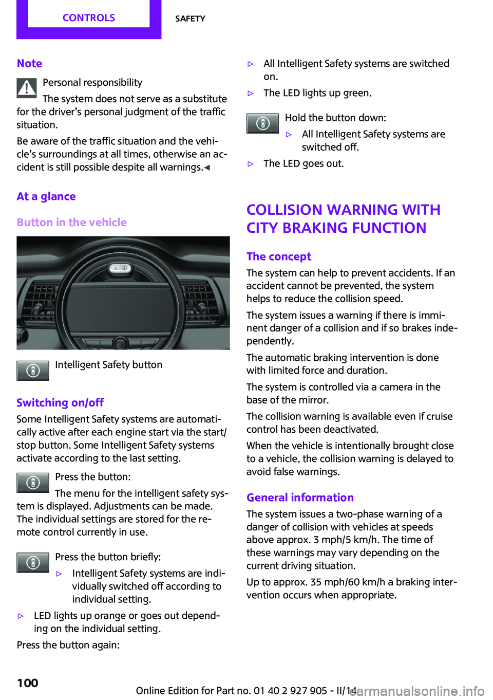
Button in the vehicle
Intelligent Safety button
Switching on/off Some Intelligent Safety systems are automati‐
cally active after each engine start via the start/
stop button. Some Intelligent Safety systems
activate according to the last setting.
Press the button:
The menu for the intelligent safety sys‐
tem is displayed. Adjustments can be made.
The individual settings are stored for the re‐
mote control currently in use.
Press the button briefly:
▷Intelligent Safety systems are indi‐
vidually switched off according to
individual setting.▷LED lights up orange or goes out depend‐
ing on the individual setting.
Press the button again:
▷All Intelligent Safety systems are switched
on.▷The LED lights up green.
Hold the button down:
▷All Intelligent Safety systems are
switched off.▷The LED goes out.
Collision warning with
City Braking function
The concept
The system can help to prevent accidents. If an
accident cannot be prevented, the system
helps to reduce the collision speed.
The system issues a warning if there is immi‐
nent danger of a collision and if so brakes inde‐
pendently.
The automatic braking intervention is done
with limited force and duration.
The system is controlled via a camera in the
base of the mirror.
The collision warning is available even if cruise
control has been deactivated.
When the vehicle is intentionally brought close to a vehicle, the collision warning is delayed to
avoid false warnings.
General information The system issues a two-phase warning of a
danger of collision with vehicles at speeds
above approx. 3 mph/5 km/h. The time of
these warnings may vary depending on the
current driving situation.
Up to approx. 35 mph/60 km/h a braking inter‐
vention occurs when appropriate.
Seite 100CONTROLSSafety100
Online Edition for Part no. 01 40 2 927 905 - II/14
Page 102 of 230
Warning with braking function
Note Adapting your speed and driving style
The warning does not relieve the driver of
the responsibility to adapt his or her driving
speed and style to the traffic conditions. ◀
Display
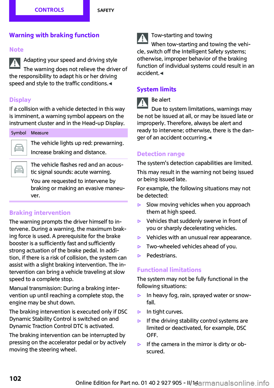
If a collision with a vehicle detected in this way
is imminent, a warning symbol appears on the
instrument cluster and in the Head-up Display.SymbolMeasureThe vehicle lights up red: prewarning.
Increase braking and distance.The vehicle flashes red and an acous‐
tic signal sounds: acute warning.
You are requested to intervene by
braking or making an evasive maneu‐
ver.
Braking intervention
The warning prompts the driver himself to in‐
tervene. During a warning, the maximum brak‐
ing force is used. A prerequisite for the brake
booster is a sufficiently fast and sufficiently
strong actuation of the brake pedal. In addi‐
tion, if there is a risk of collision, the system can
assist with a slight braking intervention. The in‐
tervention can bring a vehicle traveling at slow
speed to a complete stop.
Manual transmission: During a braking inter‐
vention up until reaching a complete stop, the
engine may be shut down.
The braking intervention is executed only if DSC
Dynamic Stability Control is switched on and
Dynamic Traction Control DTC is activated.
The braking intervention can be interrupted by
pressing on the accelerator pedal or by actively
moving the steering wheel.
Tow-starting and towing
When tow-starting and towing the vehi‐
cle, switch off the Intelligent Safety systems;
otherwise, improper behavior of the braking
function of individual systems could result in an
accident. ◀
System limits Be alert
Due to system limitations, warnings may
be not be issued at all, or may be issued late or
improperly. Therefore, always be alert and
ready to intervene; otherwise, there is the dan‐
ger of an accident occurring. ◀
Detection range The system's detection capabilities are limited.
This may result in the warning not being issued
or being issued late.
For example, the following situations may not
be detected:▷Slow moving vehicles when you approach
them at high speed.▷Vehicles that suddenly swerve in front of
you or sharply decelerating vehicles.▷Vehicles with an unusual rear appearance.▷Two-wheeled vehicles ahead of you.▷Pedestrians.
Functional limitations
The system may not be fully functional in the
following situations:
▷In heavy fog, rain, sprayed water or snow‐
fall.▷In tight curves.▷If the driving stability control systems are
limited or deactivated, for example, DSC
OFF.▷If the camera in the mirror is dirty or ob‐
scured.Seite 102CONTROLSSafety102
Online Edition for Part no. 01 40 2 927 905 - II/14
Page 103 of 230
▷During calibration of the camera immedi‐
ately after vehicle shipment.▷If there is constant dimming because of on‐
coming light, for example, from the sun low
in the sky.
Prewarning sensitivity
Depending on the set prewarning time, this
may result in increased false warnings.
Pedestrian warning with
city braking function
The concept
The system can help to prevent accidents with
pedestrians.
The system issues a warning in the city driving
speed area if there is imminent danger of a col‐
lision with pedestrians and includes a braking
function.
The system is controlled via the camera in the
base of the interior mirror.
General information
The system issues a warning with brightness
staring at approx. 6 mph/10 km/h to approx.
35 mph/60 km/h regarding a possible risk of
collision with pedestrians and assists with a
brake intervention shortly before a collision.
It responds to persons that are within the de‐
tection range of the system.
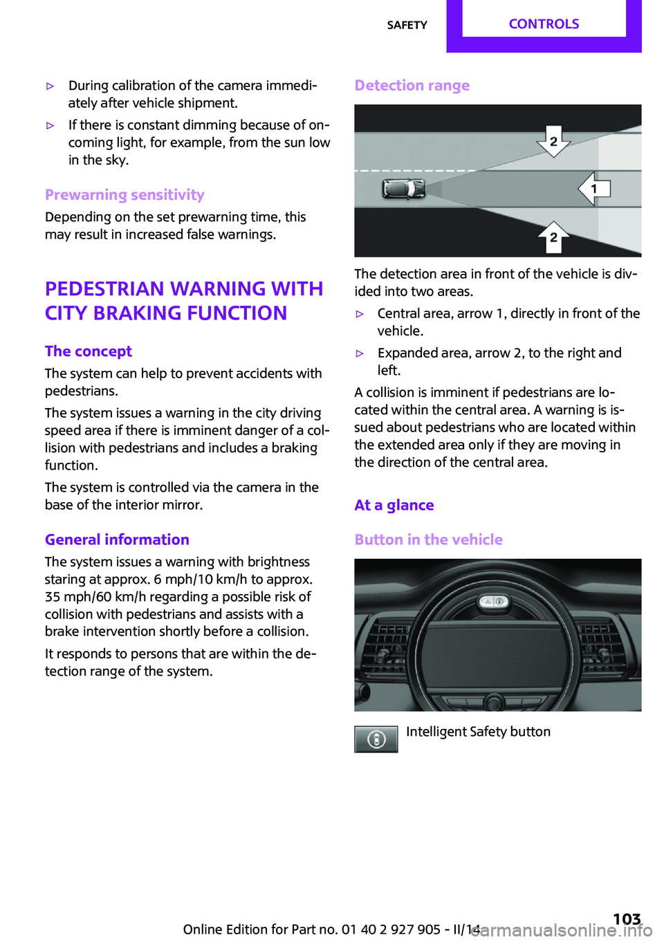
Detection range
The detection area in front of the vehicle is div‐
ided into two areas.
▷Central area, arrow 1, directly in front of the
vehicle.▷Expanded area, arrow 2, to the right and
left.
A collision is imminent if pedestrians are lo‐
cated within the central area. A warning is is‐
sued about pedestrians who are located within
the extended area only if they are moving in
the direction of the central area.
At a glance
Button in the vehicle
Intelligent Safety button
Seite 103SafetyCONTROLS103
Online Edition for Part no. 01 40 2 927 905 - II/14
Page 104 of 230

Camera
The camera is located near the base of the mir‐
ror.
Keep the windshield in the area behind the in‐
terior rearview mirror clean and clear.
Switching on/off
Switching on automatically
The system is automatically active every time
the engine is started using the Start/Stop but‐
ton.
Switching on/off manually Press the button: the menu for the in‐
telligent safety system is displayed. Ad‐
justments can be made. The individual settings
are stored for the remote control currently in
use.
Press the button briefly:
▷Intelligent Safety systems are individually
switched off according to individual setting.▷The LED lights up orange.
Press the button again:
▷All Intelligent Safety systems are switched
on.▷The LED lights up green.
Hold the button down:
▷All Intelligent Safety systems are switched
off.▷The LED goes out.Warning with braking function
Note Adapting your speed and driving style
The warning does not relieve the driver of
the responsibility to adapt his or her driving
speed and style to the traffic conditions. ◀
Display
If a collision with a person detected in this way
is imminent, a warning symbol appears on the
instrument cluster and in the Head-up Display.
The red symbol is displayed and a signalsounds.
Intervene immediately by braking or
making an evasive maneuver.
Braking intervention
The warning prompts the driver himself to in‐
tervene. During a warning, the maximum brak‐ ing force is used. A prerequisite for the brake
booster is a sufficiently fast and sufficiently
strong actuation of the brake pedal. In addi‐
tion, if there is a risk of collision, the system can
assist with a slight braking intervention. The in‐
tervention can bring a vehicle traveling at slow
speed to a complete stop.
Manual transmission: During a braking inter‐ vention up until reaching a complete stop, the
engine may be shut down.
The braking intervention is executed only if DSC
Dynamic Stability Control is switched on and
Dynamic Traction Control DTC is activated.
The braking intervention can be interrupted by
pressing on the accelerator pedal or by actively
moving the steering wheel.
Tow-starting and towing
When tow-starting and towing the vehi‐
cle, switch off the Intelligent Safety systems;
otherwise, improper behavior of the braking
function of individual systems could result in an
accident. ◀Seite 104CONTROLSSafety104
Online Edition for Part no. 01 40 2 927 905 - II/14
Page 106 of 230
Driving stability control systemsVehicle equipment
All standard, country-specific and optional
equipment that is offered in the model series is
described in this chapter. Therefore, equipment
is also described that is not available in a vehi‐
cle, e. g., because of the selected optional
equipment or country variant. This also applies
for safety-related functions and systems.
Antilock Brake System
ABS
ABS prevents locking of the wheels during
braking.
The vehicle remains steerable even during full
brake applications, thus increasing active
safety.
ABS is operational every time you start the en‐
gine.
Brake assistant When you apply the brakes rapidly, this systemautomatically produces the maximum braking
force boost. This then reduces braking distance
to a minimum during full braking. This system
utilizes all of the benefits provided by ABS.
Do not reduce the pressure on the brake pedal
for the duration of the full braking.
DSC Dynamic Stability
Control
The concept
DSC prevents traction loss in the driving wheels
when driving away and accelerating.DSC also recognizes unstable vehicle condi‐
tions, such as fishtailing or nose-diving. Subject
to physical limits, DSC helps to keep the vehicle
on a steady course by reducing engine speed
and by applying brakes to the individual
wheels.
Adjust your driving style to the situation
An appropriate driving style is always the
responsibility of the driver.
The laws of physics cannot be repealed, even
with DSC.
Therefore, do not reduce the additional safety
margin by driving in a risky manner. ◀
Indicator/warning lamps The indicator lamp flashes: DSC controls
the drive forces and brake forces.
The indicator lamp lights up: DSC has
failed.
Deactivating DSC: DSC OFF
When DSC is deactivated, driving stability is re‐
duced during acceleration and when driving in
bends.
To increase vehicle stability, activate DSC again
as soon as possible.
Deactivating DSC Press and hold the button, but not lon‐
ger than approx. 10 seconds, until the
indicator lamp for DSC OFF lights up in the in‐
strument cluster and DSC OFF is displayed.
The DSC system is switched off.
Activating DSC Press the button.Seite 106CONTROLSDriving stability control systems106
Online Edition for Part no. 01 40 2 927 905 - II/14
Page 110 of 230
Driving comfortVehicle equipment
All standard, country-specific and optional
equipment that is offered in the model series is
described in this chapter. Therefore, equipment
is also described that is not available in a vehi‐
cle, e. g., because of the selected optional
equipment or country variant. This also applies
for safety-related functions and systems.
Camera-based cruise con‐
trol, ACC
The concept
This system can be used to select a desired
speed that the vehicle will maintain automati‐
cally on clear roads.
To the extent possible, the system automati‐
cally adjusts the speed to a slower vehicle
ahead of you.
A camera on the interior rear view mirror is
used to detect vehicles driving ahead.
The distance that the vehicle maintains to the
vehicle ahead of you can be varied.
For safety reasons, it depends on the speed.
To maintain a certain distance, the system au‐
tomatically decelerates, applies the brakes
lightly, or accelerates again if the vehicle ahead
begins moving faster.
As soon as the road is clear, it accelerates to the
desired speed.
The speed is also maintained on downhill gradi‐
ents, but may not be maintained on uphill
slopes if engine power is insufficient.
General information
Depending on the set drive mode, refer to
page 108, the characteristics of the cruise con‐
trol can change in certain areas.Hints
Personal responsibility
Even an active system does not release
the driver from personal responsibility for the
driving process, especially for lane tracking, adaptation of speed, distance and driving style
to the traffic conditions.
Because of technical system limits, the system
cannot independently react appropriately in all
traffic situations.
Monitor the driving process, the surrounding
area and what is occurring in traffic continu‐
ously and attentively and actively intervene as
required, e.g., by braking, steering or making
an evasive maneuver. ◀
Unfavorable weather conditions
In the event of unfavorable weather and
light conditions, for instance if there is rain,
snowfall, slush, fog or glare, this may result in
poorer recognition of traffic situations as well
as short-term interruptions for vehicles that are
already detected. Drive attentively, and react to
the current traffic events. Intervene actively
when necessary, e.g., by braking, steering or
making an evasive maneuver, otherwise, there
is danger of an accident. ◀
At a glance
Buttons on the steering wheelPress the but‐
tonFunctionCruise control on/off, interrupt‐
ing, refer to page 111Store/maintain speed, refer to
page 112Resume speed, refer to
page 112Seite 110CONTROLSDriving comfort110
Online Edition for Part no. 01 40 2 927 905 - II/14
Page 112 of 230
Maintaining/storing the speedPress the button.
Or:
or Press button in the interrupted state.
When the system is switched on, the current
speed is maintained and stored as the desired
speed.
The speed is displayed on the symbol.
When cruise control is maintained or
stored, DSC Dynamic Stability Control is
switched on, if necessary.
Changing, maintaining, and storing the
speed
or button: by pressing one of the but‐
tons while the system is interrupted, the cur‐
rent speed can be maintained and stored. DSC
Dynamic Stability Control is switched on, if nec‐
essary.
Adapting the desired speed
Adapt the desired speed to the road con‐
ditions and be ready to brake at all times; oth‐
erwise, there is the danger of an accident oc‐
curring. ◀
Speed differences
Large differences in speed relative to
other vehicles cannot be compensated by the
system for example in the following situations:
▷When quickly approaching a slowly moving
vehicle.▷When another vehicle suddenly swerves
into the wrong lane. ◀
or button: press until the desired speed
is set.
If active, the displayed speed is stored and the
vehicle reaches the stored speed if the road is
clear.
▷ or button: each time it is pressed to
the point of resistance, the desired speedincreases or decreases by approx. 1 mph/
km/▷ or button: each time it is pressed
past the point of resistance, the desired
speed increases or decreases by a maxi‐
mum of 5 mph/10 km/h.
or button: hold down to repeat the cor‐
responding action.
Distance Selecting a distance
Adjust the distance according to the traf‐
fic and weather conditions; otherwise, there is
the danger of an accident occurring. Maintain
the prescribed safety distance. ◀
Reduce distance Press the button repeatedly until the
desired distance is set.
The set distance increment is briefly dis‐
played in the left part of the instrument
cluster.
Increase distance Press the button repeatedly until the
desired distance is set.
The set distance increment is briefly dis‐
played in the left part of the instrument
cluster.
Calling up the desired speed and
distance
While driving Press the button with the system inter‐
rupted. The regulation of the desired
speed and distance is continued with the
stored values. The selected distance is briefly
displayed in the info display.
Seite 112CONTROLSDriving comfort112
Online Edition for Part no. 01 40 2 927 905 - II/14
Page 113 of 230
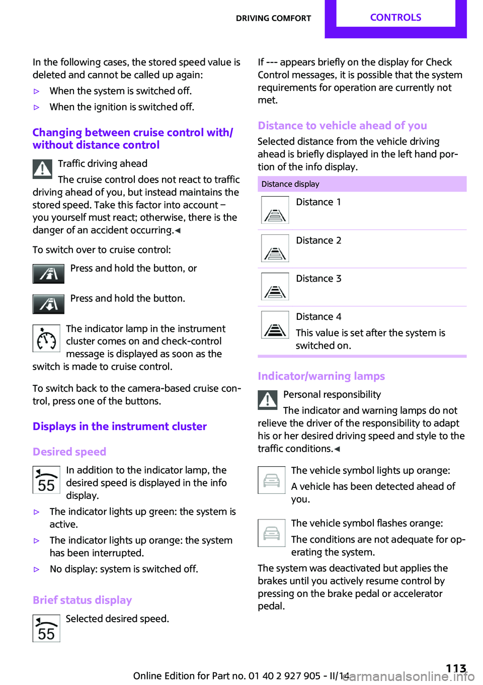
In the following cases, the stored speed value is
deleted and cannot be called up again:▷When the system is switched off.▷When the ignition is switched off.
Changing between cruise control with/
without distance control
Traffic driving ahead
The cruise control does not react to traffic
driving ahead of you, but instead maintains the
stored speed. Take this factor into account – you yourself must react; otherwise, there is the
danger of an accident occurring. ◀
To switch over to cruise control: Press and hold the button, or
Press and hold the button.
The indicator lamp in the instrument
cluster comes on and check-control
message is displayed as soon as the
switch is made to cruise control.
To switch back to the camera-based cruise con‐
trol, press one of the buttons.
Displays in the instrument cluster
Desired speed In addition to the indicator lamp, the
desired speed is displayed in the info
display.
▷The indicator lights up green: the system is
active.▷The indicator lights up orange: the system
has been interrupted.▷No display: system is switched off.
Brief status display
Selected desired speed.
If --- appears briefly on the display for Check
Control messages, it is possible that the system
requirements for operation are currently not
met.
Distance to vehicle ahead of you
Selected distance from the vehicle driving
ahead is briefly displayed in the left hand por‐
tion of the info display.Distance displayDistance 1Distance 2Distance 3Distance 4
This value is set after the system is
switched on.
Indicator/warning lamps
Personal responsibility
The indicator and warning lamps do not
relieve the driver of the responsibility to adapt
his or her desired driving speed and style to the
traffic conditions. ◀
The vehicle symbol lights up orange:
A vehicle has been detected ahead of
you.
The vehicle symbol flashes orange:
The conditions are not adequate for op‐
erating the system.
The system was deactivated but applies the
brakes until you actively resume control by
pressing on the brake pedal or accelerator
pedal.
Seite 113Driving comfortCONTROLS113
Online Edition for Part no. 01 40 2 927 905 - II/14