brake MINI COOPER 2014 Owner's Guide
[x] Cancel search | Manufacturer: MINI, Model Year: 2014, Model line: COOPER, Model: MINI COOPER 2014Pages: 230, PDF Size: 11.58 MB
Page 149 of 230

▷Drive moderately.
Hot exhaust systemHot exhaust system
High temperatures are generated in the
exhaust system.
Do not remove the heat shields installed and
never apply undercoating to them. Make sure
that flammable materials, e. g. hay, leaves,
grass, etc. do not come in contact with the hot
exhaust system during driving, while in idle po‐
sition mode, or when parked. Such contact
could lead to a fire, and with it the risk of seri‐
ous personal injury as well as property damage.
Do not touch hot exhaust pipes; otherwise,
there is the danger of getting burned. ◀
Diesel particulate filter The diesel particulate filter collects soot parti‐
cles and burns them periodically at high tem‐
peratures.
During the cleaning time of several minutes,
the following may occur:
▷Temporarily, the engine may run less
smoothly.▷Noises and a slight amount of smoke com‐
ing from the exhaust until shortly after the
engine is shut down.▷A somewhat higher engine speed is neces‐
sary to achieve the accustomed perform‐
ance.
Mobile communication devices in the vehicle
Mobile communication devices in the ve‐
hicle
It is advised that you do not use mobile com‐
munication devices, e.g., mobile phones, inside
the vehicle without connecting them directly to
the external antenna. Otherwise, the vehicle
electronics and mobile communication devices
can interfere with each other. In addition, there
is no assurance that the radiation generated
during transmission will be discharged from the
vehicle interior. ◀
Hydroplaning On wet or slushy roads, a wedge of water can
form between the tires and road surface.
This phenomenon is referred to as hydroplan‐
ing. It is characterized by a partial or complete
loss of contact between the tires and the road
surface, ultimately undermining your ability to
steer and brake the vehicle.
Hydroplaning
When driving on wet or slushy roads, re‐
duce your speed to prevent hydroplaning. ◀
Driving through water Drive through calm water only if it is not deeper
than 9.8 inches/25 cm and at this height, no
faster than walking speed, up to
6 mph/10 km/h.
Adhere to water depth and speed limita‐
tions
Do not exceed this water depth and walking
speed; otherwise, the vehicle's engine, the
electrical systems and the transmission may be
damaged. ◀
Braking safely
Your vehicle is equipped with ABS as a standard
feature.
Applying the brakes fully is the most effective
way of braking in situations when this is neces‐
sary.
The vehicle maintains steering responsiveness.
You can still avoid any obstacles with a mini‐
mum of steering effort.
Pulsation of the brake pedal and sounds from
the hydraulic circuits indicate that ABS is in its
active mode.Seite 149Things to remember when drivingDRIVING TIPS149
Online Edition for Part no. 01 40 2 927 905 - II/14
Page 150 of 230

Objects in the area around the pedalsNo objects in the area around the pedals
Keep floor mats, carpets, and any other
objects out of the area of motion of the pedals;
otherwise, the function of the pedals could be
impeded while driving and create the risk of an
accident.
Do not place additional floor mats over existing
mats or other objects.
Only use floor mats that have been approved for the vehicle and can be properly fixed in
place.
Ensure that the floor mats are securely fastened
again after they were removed for cleaning, for
example. ◀
Driving in wet conditions When roads are wet or there is heavy rain,
briefly exert gentle pressure on the brake pedal
every few miles.
Ensure that this action does not endanger other
road users.
The heat generated in this process helps dry
the brake discs and pads.
In this way braking efficiency will be available
when you need it.
HillsDrive long or steep downhill gradients in the
gear in which the least braking is required. Oth‐
erwise, the brake system may overheat, result‐
ing in a reduction in the brake system effi‐
ciency.
You can increase the engine's braking effect by
shifting down, going all the way to first gear, if
necessary.
Avoid load on the brakes
Avoid placing excessive load on the brake
system. Light but consistent brake pressure can
lead to high temperatures, brake wear and
possibly even brake failure. ◀Do not drive in neutral
Do not drive in neutral or with the engine
stopped, as doing so disables engine braking.
In addition, steering and brake assist are un‐
available with the engine stopped. ◀
Brake disc corrosion Corrosion on the brake discs and contamina‐
tion on the brake pads are furthered by:▷Low mileage.▷Extended periods when the vehicle is not
used at all.▷Infrequent use of the brakes.
Corrosion occurs when the minimum pressure
that must be exerted by the pads during brake
applications to clean the discs is not reached.
Should corrosion form on the brake discs, the
brakes will tend to respond with a pulsating ef‐
fect that generally cannot be corrected.
Condensation under the parked vehicle
When using the automatic climate control, con‐
densation water develops that exits under‐
neath the vehicle.
Traces of water under the vehicle like this are
normal.
Ground clearance Limited ground clearance
Observe the limited ground clearance of
the vehicle, e. g. while entering underground
parking garages or when driving over obsta‐
cles. Otherwise, damages to the vehicle may
result. ◀
Seite 150DRIVING TIPSThings to remember when driving150
Online Edition for Part no. 01 40 2 927 905 - II/14
Page 153 of 230
Securing
Follow the installation instructions of the roof
rack.
Loading Be sure that adequate clearance is maintained
for tilting and opening the glass sunroof.
Because roof racks raise the vehicle's center of
gravity when loaded, they have a major effect
on vehicle handling and steering response.
Therefore, note the following when loading and
driving:▷Do not exceed the approved roof/axle
loads and the approved gross vehicle
weight.▷Distribute the roof load uniformly.▷The roof load should not be too large in
area.▷Always place the heaviest pieces on the
bottom.▷Secure the roof luggage firmly, e.g., tie with
ratchet straps.▷Do not let objects project into the opening
path of the tailgate.▷Drive cautiously and avoid sudden acceler‐
ation and braking maneuvers. Take corners
gently.
Rear luggage rack
General information Installation only possible with rear luggage rack
preparation.
Rear racks are available as special accessories.
Note Follow the installation instructions of the rear
luggage rack.
Drive cautiously and avoid sudden acceleration
and braking maneuvers. Take corners gently.
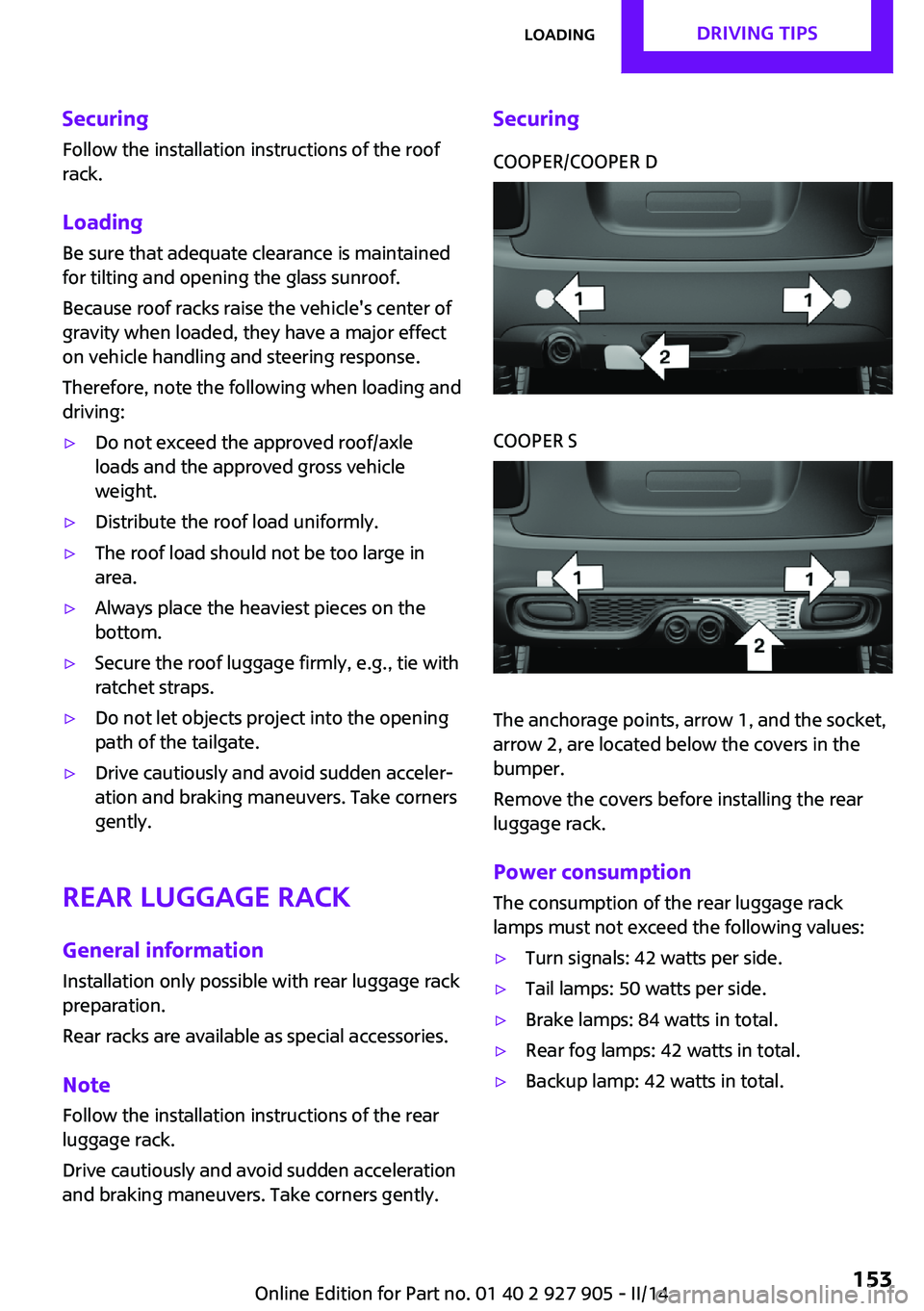
SecuringCOOPER/COOPER DCOOPER S
The anchorage points, arrow 1, and the socket,
arrow 2, are located below the covers in the
bumper.
Remove the covers before installing the rear
luggage rack.
Power consumption
The consumption of the rear luggage rack
lamps must not exceed the following values:
▷Turn signals: 42 watts per side.▷Tail lamps: 50 watts per side.▷Brake lamps: 84 watts in total.▷Rear fog lamps: 42 watts in total.▷Backup lamp: 42 watts in total.Seite 153LoadingDRIVING TIPS153
Online Edition for Part no. 01 40 2 927 905 - II/14
Page 159 of 230

SymbolMeasureManual shift transmission: follow
shifting instructions.Manual shift transmission: engage
neutral for engine stop.
Indications on the Control Display
MINIMALISM
Information on fuel consumption and technol‐
ogy can be displayed during driving.
1. "Vehicle Info"2."MINIMALISM"
Displaying MINIMALISM info
The current efficiency can be displayed.
"MINIMALISM info"
The following systems are displayed:
▷Automatic engine Start/Stop function.▷Energy recovery.▷Climate control output.▷Coasting.
Displaying GREEN mode tips
"GREEN Tips"
Driving instruction and an additional symbol
are displayed.
The setting is stored for the profile currently in
use.
Coasting
The concept
The system helps to conserve fuel.
To do this, under certain conditions the engine
is automatically decoupled from the transmis‐
sion when selector lever position D is engaged.
The vehicle continues traveling with the engine
idling to reduce fuel consumption. Selector
lever position D remains engaged.
This driving condition is referred to as coasting.
As soon as the brake or accelerator pedal is de‐
pressed, the engine is automatically coupled to
the transmission again.
Hints
Coasting is a component of the GREEN mode,
refer to page 156, driving mode.
Coasting is automatically activated when
GREEN mode is called via the Driving Dynamics
Control, refer to page 108.
The function is available in a certain speed
range.
A forward-looking driving style helps the driver
to use the function as often as possible and
supports the fuel-conserving effect of coasting.
Safety mode
The function is not available if one of the fol‐
lowing conditions is satisfied.▷DSC OFF or TRACTION activated.▷Driving in the dynamic limit range and on
steep uphill or downhill grades.▷Battery charge status temporarily too low
or vehicle electrical system drawing exces‐
sive current.▷Cruise control activated.
Functional requirements
In GREEN mode, this function is available in a
speed range from approximately 30 mph, ap‐
prox. 50 km/h to 100 mph, approx. 160 km/h,
if the following conditions are satisfied:
▷Accelerator pedal and brake pedal are not
operated.▷The selector lever is in transmission position
D.▷Engine and transmission are at operating
temperature.Seite 159Saving fuelDRIVING TIPS159
Online Edition for Part no. 01 40 2 927 905 - II/14
Page 175 of 230

Run-flat tiresLabel
RSC label on the tire sidewall.
The wheels are composed of tires that are self-
supporting to a limited degree.
The support of the sidewall allows the tire to re‐
main drivable to a restricted degree in the
event of a pressure loss.
Continued driving with a damaged tire, refer to
page 99.
Continued driving with a damaged tire, refer to
page 96.
Changing run-flat tires
For your own safety, only use run-flat tires. No
spare tire is available in the case of a flat tire.
Your service center will be glad to advise you.
Repairing a flat tire Safety measures in case of a breakdown
Park the vehicle as far away as possible
from passing traffic and on solid ground.
Switch on the hazard warning system.
Turn the steering wheel until the front wheels
are in the straight-ahead position and engage
the steering wheel lock.
Secure the vehicle against rolling away by set‐
ting the parking brake.
Have all vehicle occupants get out of the vehi‐
cle and ensure that they remain outside the im‐
mediate area in a safe place, such as behind a
guardrail.
If necessary, set up a warning triangle at an ap‐
propriate distance.
Comply with all safety guidelines and regula‐
tions. ◀
Mobility System
The concept
With the Mobility System, minor tire damage
can be sealed quickly to enable continued travel. To accomplish this, sealant is pumped
into the tires, which seals the damage from the
inside.
The compressor can be used to check the tire
inflation pressure.
Hints▷Follow the instructions on using the Mobi‐
lity System found on the compressor and
sealant bottle.▷Use of the Mobility System may be ineffec‐
tive if the tire puncture measures approx.
1/8 in/4 mm or more.▷Contact the nearest service center if the tire
cannot be made drivable.▷If possible, do not remove foreign bodies
that have penetrated the tire.▷Pull the speed limit sticker off the sealant
bottle and apply it to the steering wheel.▷The use of a tire sealant can damage the
TPM wheel electronics. In this case, have
the electronics checked at the next oppor‐
tunity and have them replaced if necessary.
Storage
The Mobility System is located under the cargo
floor panel in the cargo area.
Seite 175Wheels and tiresMOBILITY175
Online Edition for Part no. 01 40 2 927 905 - II/14
Page 186 of 230

MaintenanceVehicle equipment
All standard, country-specific and optional
equipment that is offered in the model series is
described in this chapter. Therefore, equipment
is also described that is not available in a vehi‐
cle, e. g., because of the selected optional
equipment or country variant. This also applies
for safety-related functions and systems.
MINI maintenance system
The maintenance system indicates required
maintenance measures, and thereby provides
support in maintaining road safety and the op‐
erational reliability of the vehicle.
Condition Based Service
CBS
Sensors and special algorithms take into ac‐
count the driving conditions of your vehicle.
Based on this, Condition Based Service deter‐
mines the maintenance requirements.
The system makes it possible to adapt the
amount of maintenance you need to your user
profile.
Detailed information on service requirements,
refer to page 76, can be displayed on the Con‐
trol Display.
Service data in the remote control
Information on the required maintenance is
continuously stored in the remote control. Your
service center will read out this data and sug‐
gest the right array of service procedures for
your vehicle.
Therefore, hand your service specialist the re‐
mote control that you used most recently.Storage periods
Storage periods during which the vehicle bat‐
tery was disconnected are not taken into ac‐
count.
If this occurs, have a service center update the
time-dependent maintenance procedures, such
as checking brake fluid and, if necessary,
changing the engine oil and the microfilter/acti‐
vated-charcoal filter.
Service and Warranty In‐
formation Booklet for
US models and Warranty
and Service Guide Book‐
let for Canadian models
Please consult your Service and Warranty Infor‐
mation Booklet for US models and Warranty
and Service Guide Booklet for Canadian models
for additional information on service require‐
ments.
Maintenance and repair should be performed
by your service center. Make sure to have regu‐
lar maintenance procedures recorded in the ve‐
hicle's Service and Warranty Information Book‐
let for US models, and in the Warranty and
Service Guide Booklet for Canadian models.
These entries are proof of regular maintenance.
Socket for OBD Onboard
Diagnosis
Note Socket for Onboard Diagnosis
The socket for onboard diagnostics may
only be used by the service center or a work‐ shop that operates in accordance with theSeite 186MOBILITYMaintenance186
Online Edition for Part no. 01 40 2 927 905 - II/14
Page 192 of 230

Parking lamps/fog lamps/daytime
running lights
Follow the general instructions on Lamps and
bulbs, refer to page 189.
Bulbs:▷Parking lamps for halogen headlamps:
W5W
Parking lamps for LED headlamps:
W5W NBV▷Daytime running light: PSX24W▷Fog lamp: H81.Turn the steering wheel.2.Turn the lid counterclockwise, arrow 2, and
remove.3.Remove the corresponding connector.4.▷Remove bulb socket of the parking
lamp, arrow 1, by turning it counter‐
clockwise.
Pull the bulb out of the fixture.▷Remove the bulb socket of the daytime
running lights, arrow 2, by pressing to‐
gether the top and bottom latch mech‐
anism.
For better accessibility, if necessary, re‐
move the bulb of the fog lamp before‐
hand.▷Turn the bulb socket of the fog lamp
counterclockwise, arrow 3, and re‐
move.5.Insert the new bulbs and install the cover in
the reverse order.
When installing the daytime running lights,
audibly latch the bulb socket first at the
bottom, then at the top.
Tail lamps, bulb replacement
At a glance
Vehicles with a rear fog lamp
1Side tail lamps2Rear fog lamp3License plate lamp4High brake lightsSeite 192MOBILITYReplacing components192
Online Edition for Part no. 01 40 2 927 905 - II/14
Page 193 of 230

Vehicle with two rear fog lamps1Side tail lamps2Rear fog lamps3License plate lamp4High brake lights
Side tail lamps
1Brake lights/tail lights2Turn signal3Reversing lightsSide LED tail lamps1Brake lights/tail lights2Turn signal3Reversing lights
Side tail lampsFollow the general instructions on lamps and
bulbs, refer to page 189.
Bulbs: P21W
1.Open the tailgate., refer to page 392.Remove left or right cover.3.Through the opening, loosen the plug con‐
nector, arrow 2 on the bulb holder.Seite 193Replacing componentsMOBILITY193
Online Edition for Part no. 01 40 2 927 905 - II/14
Page 194 of 230

Push apart the latches, arrows 1, and re‐
move the bulb holder.4.Remove the bulb holder from the opening.5.Press the defective bulb gently into the
socket, turn clockwise and remove.▷Arrow 1: brake lights/tail lights▷Arrow 2: turn signal▷Arrow 3: reversing light6.Proceed in the reverse order to insert the
new bulb and attach the bulb holder. Make
sure that the bulb holder engages in all fas‐
teners.
Central brake lamp and license plate
lamp
Follow the general instructions on lamps and
bulbs, refer to page 189.
The lamps feature LED technology. Contact your service center in the event of a malfunc‐
tion.
Vehicles with a rear fog lamp
Follow the general instructions on Lamps and
bulbs, refer to page 189.
Bulbs: W16W1.On vehicles with heat shield:
Loosen 3 screws, arrow.2.Push the heat shield forward and the
bumper back in order to be able to reach
the fog lamp.3.Turn the bulb socket counterclockwise and
remove.
The wire is long enough to guide the socket
down and through between any heat shield
that may be installed and the bumper.4.Replace defective bulb.5.To install the new bulb, proceed in reverse
order of removal.
Vehicle with two rear fog lamps
Follow the general instructions on Lamps and
bulbs, refer to page 189.
Bulbs: W16W
Left rear fog lamp:
1.On vehicles with heat shield:Seite 194MOBILITYReplacing components194
Online Edition for Part no. 01 40 2 927 905 - II/14
Page 196 of 230

▷With white lens: WY5W diadem1.Push turn signal housing up and pull out at
the bottom.2.Turn the bulb socket counterclockwise and
remove.3.Replace the bulb.4.Proceed in the reverse order to insert the
new bulb and install the turn signal hous‐
ing.
First hook the turn signal housing to the
bottom, then at the top press it into the
latch.
Changing wheels
Hints
The vehicle equipment does not include a
spare tire.
When using run-flat tires or tire sealants, a tire
does not need to be changed immediately in
the event of pressure loss due to a flat tire.
The tools for changing wheels are available as
accessories from your service center.
Jacking points for the vehicle jack
The jacking points for the vehicle jack are lo‐
cated at the positions shown.
Compact wheel
Hints Safety measures in case of a breakdown
or a wheel change
▷Park the vehicle as far away as possible
from passing traffic and on solid ground.
Switch on the hazard warning system.▷Set the parking brake, and engage first gear
or transmission position P.▷Have all vehicle occupants get out of the
vehicle and ensure that they remain out‐
side the immediate area in a safe place,
such as behind a guardrail.▷If necessary, set up a warning triangle or
portable hazard warning lamp at an appro‐
priate distance. Comply with all safety
guidelines and regulations.▷Perform wheel change only on a flat, solid
and slip-resistant surface. On soft or slip‐
pery ground, e.g., snow, ice, tiles, etc., the
vehicle or vehicle jack can slip away to the
side.▷Do not place wood blocks or similar items
under the vehicle jack; otherwise, it cannot
reach its carrying capacity because of the
restricted height.▷If the vehicle is raised, do not lie under the
vehicle and do not start the engine; other‐
wise, a mortal hazard exists. ◀Seite 196MOBILITYReplacing components196
Online Edition for Part no. 01 40 2 927 905 - II/14