display MINI COOPER 2014 Manual PDF
[x] Cancel search | Manufacturer: MINI, Model Year: 2014, Model line: COOPER, Model: MINI COOPER 2014Pages: 230, PDF Size: 11.58 MB
Page 129 of 230
Windshield defrosterPress the button.
The front window defroster switches
off automatically after a certain period of time.
Switching the system on/off
Switching off Turn wheel for air quantity to the
left until the control switches off.Switching on
Set any air volume.
Microfilter
In external and recirculated air mode the mi‐
crofilter filters dust and pollen out of the air.
This filter should be replaced during scheduled
maintenance, refer to page 186, of your vehi‐
cle.
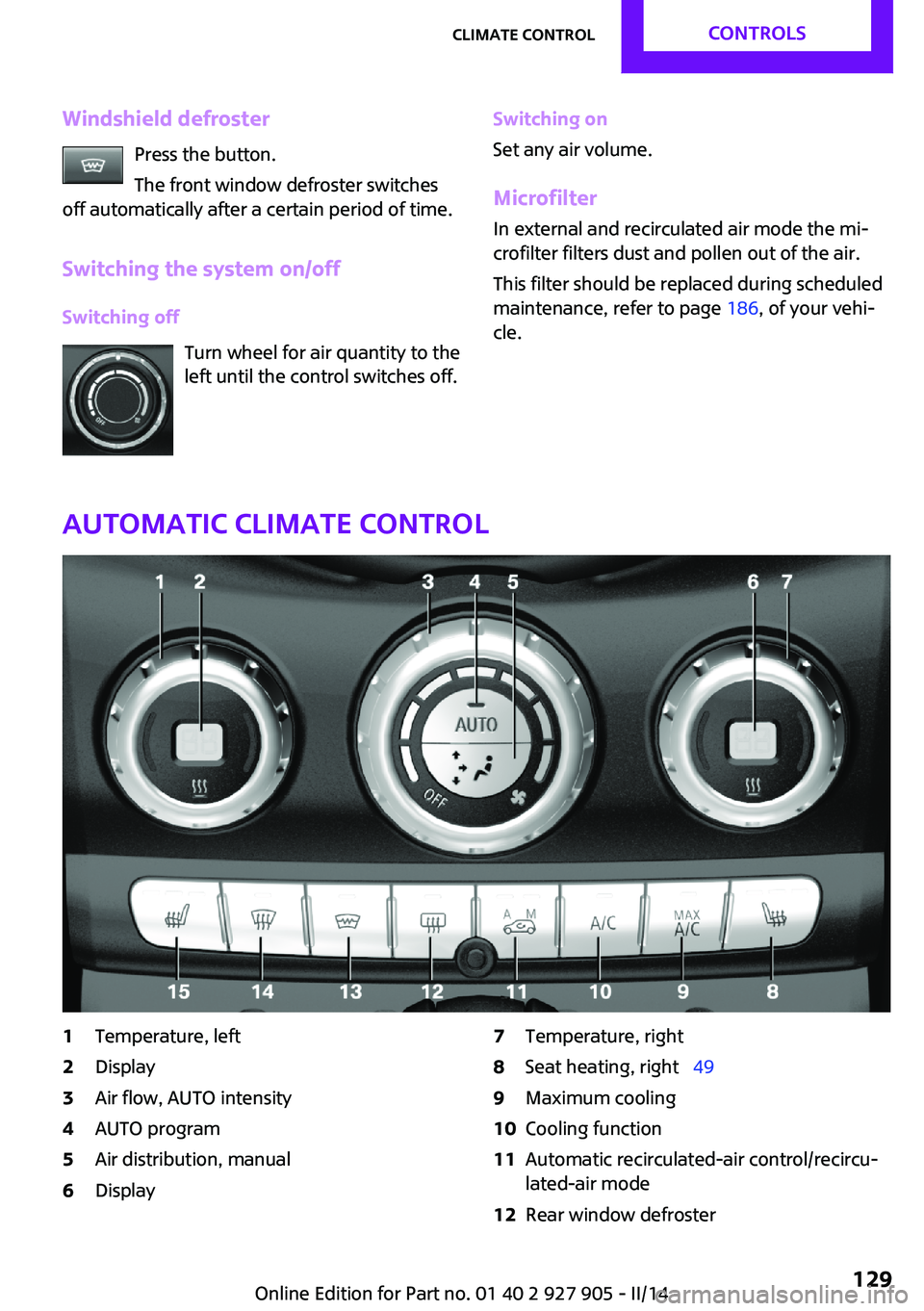
Automatic climate control
1Temperature, left2Display3Air flow, AUTO intensity4AUTO program5Air distribution, manual6Display7Temperature, right8Seat heating, right 499Maximum cooling10Cooling function11Automatic recirculated-air control/recircu‐
lated-air mode12Rear window defrosterSeite 129Climate controlCONTROLS129
Online Edition for Part no. 01 40 2 927 905 - II/14
Page 130 of 230
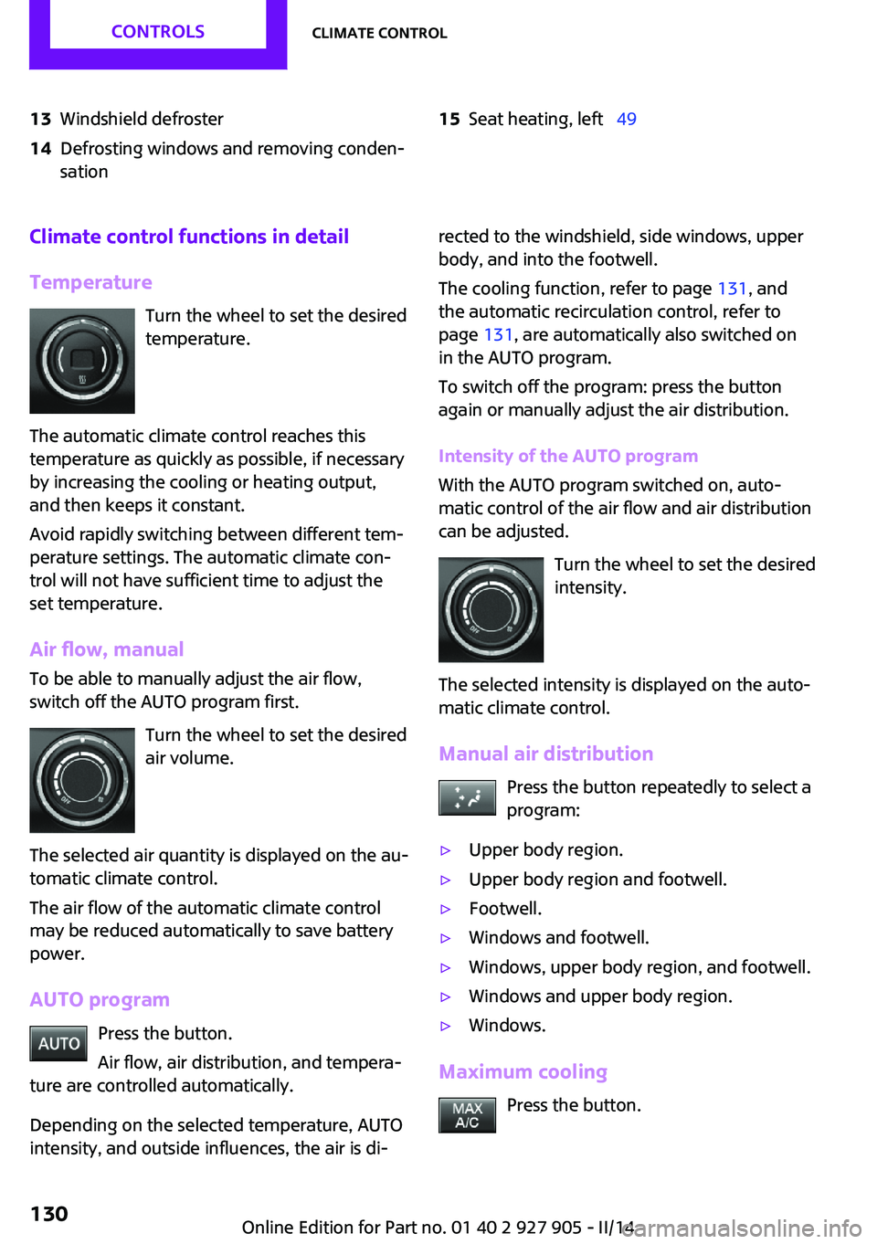
13Windshield defroster14Defrosting windows and removing conden‐
sation15Seat heating, left 49Climate control functions in detail
Temperature Turn the wheel to set the desired
temperature.
The automatic climate control reaches this
temperature as quickly as possible, if necessary
by increasing the cooling or heating output,
and then keeps it constant.
Avoid rapidly switching between different tem‐
perature settings. The automatic climate con‐
trol will not have sufficient time to adjust the
set temperature.
Air flow, manual
To be able to manually adjust the air flow,
switch off the AUTO program first.
Turn the wheel to set the desired
air volume.
The selected air quantity is displayed on the au‐
tomatic climate control.
The air flow of the automatic climate control
may be reduced automatically to save battery
power.
AUTO program Press the button.
Air flow, air distribution, and tempera‐
ture are controlled automatically.
Depending on the selected temperature, AUTO
intensity, and outside influences, the air is di‐rected to the windshield, side windows, upper
body, and into the footwell.
The cooling function, refer to page 131, and
the automatic recirculation control, refer to
page 131, are automatically also switched on
in the AUTO program.
To switch off the program: press the button
again or manually adjust the air distribution.
Intensity of the AUTO program
With the AUTO program switched on, auto‐
matic control of the air flow and air distribution can be adjusted.
Turn the wheel to set the desired
intensity.
The selected intensity is displayed on the auto‐
matic climate control.
Manual air distribution Press the button repeatedly to select a
program:▷Upper body region.▷Upper body region and footwell.▷Footwell.▷Windows and footwell.▷Windows, upper body region, and footwell.▷Windows and upper body region.▷Windows.
Maximum cooling
Press the button.
Seite 130CONTROLSClimate control130
Online Edition for Part no. 01 40 2 927 905 - II/14
Page 135 of 230

4.Likewise, press and hold the button of the
desired function on the hand-held trans‐
mitter.5.Release both buttons as soon as the interior
rearview mirror LED flashes more rapidly.
When the LED is flashing faster, this indi‐
cates that the button on the interior rear‐
view mirror has been programmed. The
system can then be controlled by the but‐
ton on the interior rearview mirror.
If the LED does not flash faster after at least
60 seconds, change the distance and re‐
peat the step. Several more attempts at dif‐
ferent distances may be necessary. Wait at
least 15 seconds between attempts.
Canada: if programming with the hand-
held transmitter was interrupted, hold
down the interior rearview mirror button
and repeatedly press and release the hand-
held transmitter button for 2 seconds.
Controls
Before operation
Before operating a system using the
integrated universal remote control, ensure
that there are no people, animals, or objects
within the range of movement of the remote-
controlled system; otherwise, there is a risk of
injury or damage.
Also follow the safety instructions of the hand- held transmitter. ◀
The system, such as the garage door, can be
operated using the button on the interior rear‐
view mirror while the engine is running or
when the ignition is started. To do this, hold down the button within receiving range of the
system until the function is activated. The inte‐
rior rearview mirror LED stays lit while the wire‐
less signal is being transmitted.
Deleting stored functions
Press and hold the left and right button on the
interior rearview mirror simultaneously for ap‐
proximately 20 seconds until the LED flashes
rapidly. All stored functions are deleted. The
functions cannot be deleted individually.
Digital compass
At a glance1Control button2Mirror display
Mirror display The point of the compass is displayed in the
mirror when driving straight.
Operating concept Various functions can be called up by pressing
the control button with a pointed object, such
as the tip of a ballpoint pen or similar object.
The following setting options are displayed in
succession, depending on how long the control
button is pressed:
▷Pressed briefly: turns display on/off.▷3 to 6 seconds: compass zone setting.▷6 to 9 seconds: compass calibration.▷9 to 12 seconds: left/right-hand steering
setting.▷12 to 15 seconds: language setting.
Setting the compass zones
Sets the particular compass zones on the vehi‐
cle so that the compass operates correctly; re‐
fer to World map with compass zones.
Seite 135Interior equipmentCONTROLS135
Online Edition for Part no. 01 40 2 927 905 - II/14
Page 136 of 230
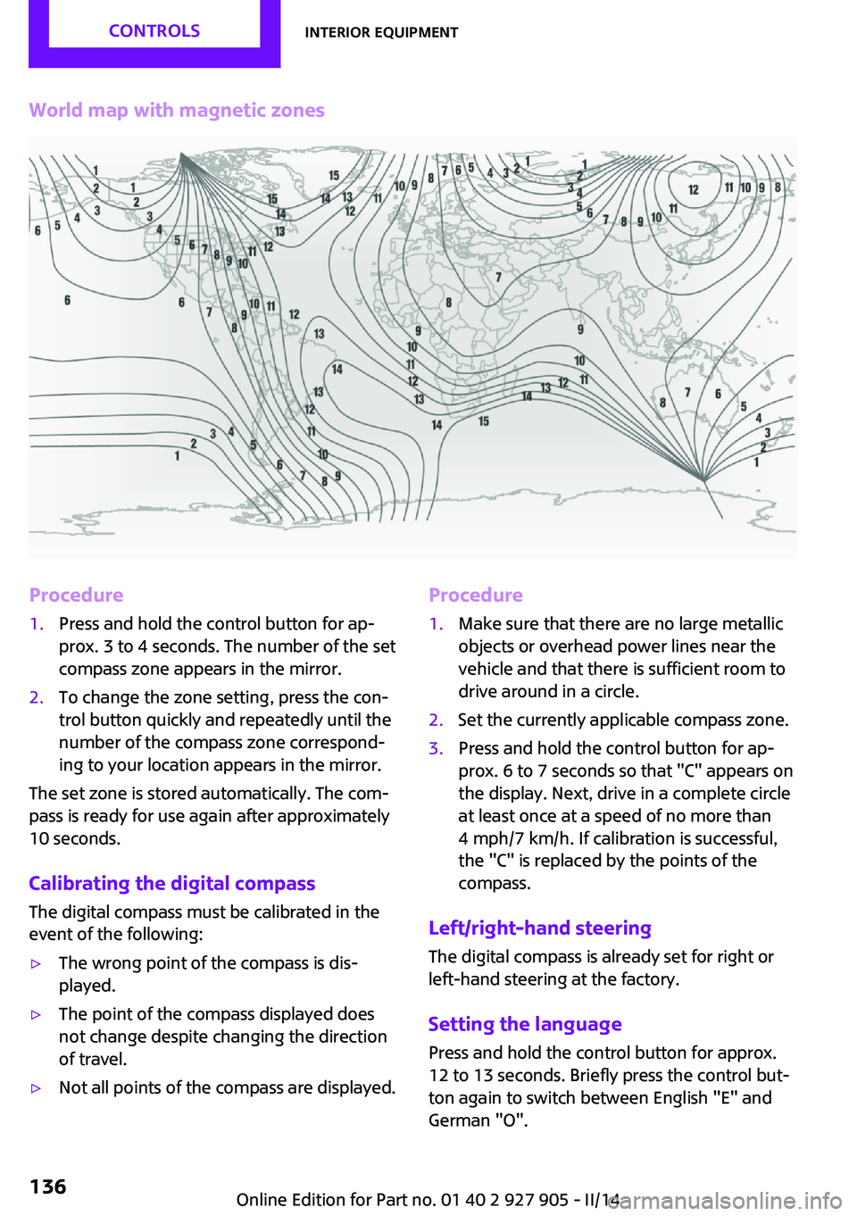
World map with magnetic zonesProcedure1.Press and hold the control button for ap‐
prox. 3 to 4 seconds. The number of the set
compass zone appears in the mirror.2.To change the zone setting, press the con‐
trol button quickly and repeatedly until the
number of the compass zone correspond‐
ing to your location appears in the mirror.
The set zone is stored automatically. The com‐
pass is ready for use again after approximately
10 seconds.
Calibrating the digital compass The digital compass must be calibrated in the
event of the following:
▷The wrong point of the compass is dis‐
played.▷The point of the compass displayed does
not change despite changing the direction
of travel.▷Not all points of the compass are displayed.Procedure1.Make sure that there are no large metallic
objects or overhead power lines near the
vehicle and that there is sufficient room to
drive around in a circle.2.Set the currently applicable compass zone.3.Press and hold the control button for ap‐
prox. 6 to 7 seconds so that "C" appears on
the display. Next, drive in a complete circle
at least once at a speed of no more than
4 mph/7 km/h. If calibration is successful,
the "C" is replaced by the points of the
compass.
Left/right-hand steering
The digital compass is already set for right or
left-hand steering at the factory.
Setting the language
Press and hold the control button for approx.
12 to 13 seconds. Briefly press the control but‐ ton again to switch between English "E" and
German "O".
Seite 136CONTROLSInterior equipment136
Online Edition for Part no. 01 40 2 927 905 - II/14
Page 157 of 230
consumption. Selector lever position D remains
engaged. An indicator provides information
about the distance traveled in Coasting mode.
In addition, context-sensitive instructions can
be displayed that assist in driving in a manner
that optimizes fuel consumption.
The extension of the range that is achieved as a
result can be displayed in the instrument clus‐
ter.
At a glance
The system includes the following MINIMALISM
functions and displays:▷GREEN bonus range, refer to page 158▷GREEN tips driving instruction, refer to
page 158▷GREEN climate control, refer to page 157▷MINIMALISM analyzer, refer to page 160▷Coasting driving condition, refer to
page 159
Activating GREEN mode
Turn Driving Dynamics Control to
the right until GREEN mode is
displayed in the instrument clus‐
ter.
Configuring GREEN mode
Via the Driving Dynamics Control
1.Activating GREEN mode.2."Configure GREEN"3.Configure the program.
Via onboard monitor:
1. "Settings"2."GREEN Mode"
Or
1. "Settings"2."Driving mode"3."Configure GREEN"
Configure the program.
GREEN tip
▷"Tip at:":
Set the GREEN mode speed at which a
GREEN mode tip is to be displayed.▷"GREEN speed warning":
A reminder is displayed if the set GREEN
mode speed is exceeded.
Coasting
Fuel-efficiency can be optimized by disengag‐
ing the engine and Coasting, refer to page 159,
with the engine idling.
This function is only available in GREEN mode.
GREEN climate control
"GREEN climate control"
The climate control is adjusted to be fuel-effi‐
cient.
By making a slight change to the set tempera‐
ture, or adjusting the rate of heating or cooling
of the passenger compartment fuel consump‐
tion can be economized.
The outputs of the seat heater and the exterior
mirror heating are also reduced.
The exterior mirror heating is made available
when outside temperatures are very cold.
GREEN potential
The percentage of potential savings that can be
achieved with the current configuration is dis‐
played.
Seite 157Saving fuelDRIVING TIPS157
Online Edition for Part no. 01 40 2 927 905 - II/14
Page 158 of 230
Display in the instrument cluster
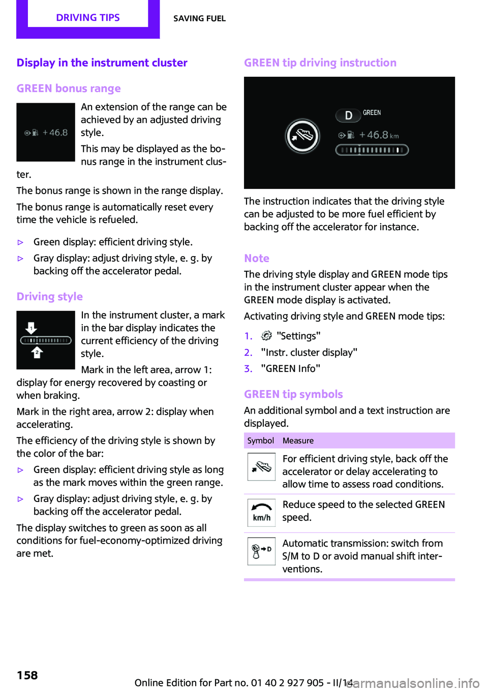
GREEN bonus range An extension of the range can be
achieved by an adjusted driving
style.
This may be displayed as the bo‐
nus range in the instrument clus‐
ter.
The bonus range is shown in the range display.
The bonus range is automatically reset every
time the vehicle is refueled.▷Green display: efficient driving style.▷Gray display: adjust driving style, e. g. by
backing off the accelerator pedal.
Driving style
In the instrument cluster, a mark
in the bar display indicates the
current efficiency of the driving
style.
Mark in the left area, arrow 1:
display for energy recovered by coasting or
when braking.
Mark in the right area, arrow 2: display when
accelerating.
The efficiency of the driving style is shown by
the color of the bar:
▷Green display: efficient driving style as long
as the mark moves within the green range.▷Gray display: adjust driving style, e. g. by
backing off the accelerator pedal.
The display switches to green as soon as all
conditions for fuel-economy-optimized driving
are met.
GREEN tip driving instruction
The instruction indicates that the driving style
can be adjusted to be more fuel efficient by
backing off the accelerator for instance.
Note
The driving style display and GREEN mode tips
in the instrument cluster appear when the
GREEN mode display is activated.
Activating driving style and GREEN mode tips:
1. "Settings"2."Instr. cluster display"3."GREEN Info"
GREEN tip symbols An additional symbol and a text instruction are
displayed.
SymbolMeasureFor efficient driving style, back off the
accelerator or delay accelerating to
allow time to assess road conditions.Reduce speed to the selected GREEN
speed.Automatic transmission: switch from
S/M to D or avoid manual shift inter‐
ventions.Seite 158DRIVING TIPSSaving fuel158
Online Edition for Part no. 01 40 2 927 905 - II/14
Page 159 of 230
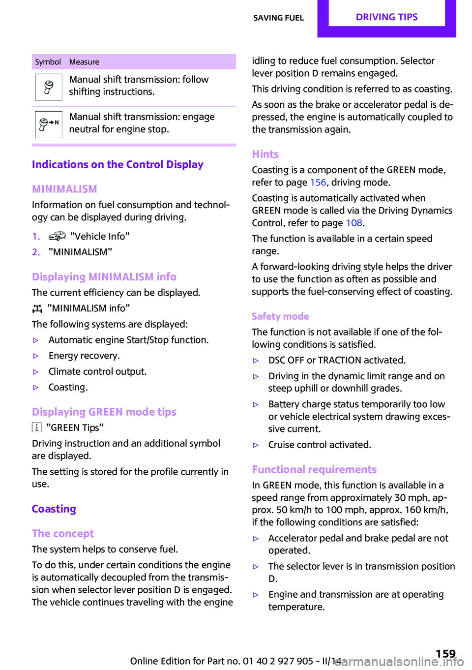
SymbolMeasureManual shift transmission: follow
shifting instructions.Manual shift transmission: engage
neutral for engine stop.
Indications on the Control Display
MINIMALISM
Information on fuel consumption and technol‐
ogy can be displayed during driving.
1. "Vehicle Info"2."MINIMALISM"
Displaying MINIMALISM info
The current efficiency can be displayed.
"MINIMALISM info"
The following systems are displayed:
▷Automatic engine Start/Stop function.▷Energy recovery.▷Climate control output.▷Coasting.
Displaying GREEN mode tips
"GREEN Tips"
Driving instruction and an additional symbol
are displayed.
The setting is stored for the profile currently in
use.
Coasting
The concept
The system helps to conserve fuel.
To do this, under certain conditions the engine
is automatically decoupled from the transmis‐
sion when selector lever position D is engaged.
The vehicle continues traveling with the engine
idling to reduce fuel consumption. Selector
lever position D remains engaged.
This driving condition is referred to as coasting.
As soon as the brake or accelerator pedal is de‐
pressed, the engine is automatically coupled to
the transmission again.
Hints
Coasting is a component of the GREEN mode,
refer to page 156, driving mode.
Coasting is automatically activated when
GREEN mode is called via the Driving Dynamics
Control, refer to page 108.
The function is available in a certain speed
range.
A forward-looking driving style helps the driver
to use the function as often as possible and
supports the fuel-conserving effect of coasting.
Safety mode
The function is not available if one of the fol‐
lowing conditions is satisfied.▷DSC OFF or TRACTION activated.▷Driving in the dynamic limit range and on
steep uphill or downhill grades.▷Battery charge status temporarily too low
or vehicle electrical system drawing exces‐
sive current.▷Cruise control activated.
Functional requirements
In GREEN mode, this function is available in a
speed range from approximately 30 mph, ap‐
prox. 50 km/h to 100 mph, approx. 160 km/h,
if the following conditions are satisfied:
▷Accelerator pedal and brake pedal are not
operated.▷The selector lever is in transmission position
D.▷Engine and transmission are at operating
temperature.Seite 159Saving fuelDRIVING TIPS159
Online Edition for Part no. 01 40 2 927 905 - II/14
Page 160 of 230
Display
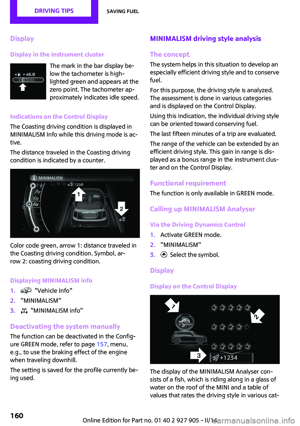
Display in the instrument cluster The mark in the bar display be‐
low the tachometer is high‐
lighted green and appears at the
zero point. The tachometer ap‐
proximately indicates idle speed.
Indications on the Control Display
The Coasting driving condition is displayed in
MINIMALISM Info while this driving mode is ac‐
tive.
The distance traveled in the Coasting driving
condition is indicated by a counter.
Color code green, arrow 1: distance traveled in
the Coasting driving condition. Symbol, ar‐
row 2: coasting driving condition.
Displaying MINIMALISM info
1. "Vehicle Info"2."MINIMALISM"3. "MINIMALISM info"
Deactivating the system manually The function can be deactivated in the Config‐
ure GREEN mode, refer to page 157, menu,
e.g., to use the braking effect of the engine
when traveling downhill.
The setting is saved for the profile currently be‐
ing used.
MINIMALISM driving style analysis
The concept
The system helps in this situation to develop an
especially efficient driving style and to conserve
fuel.
For this purpose, the driving style is analyzed.
The assessment is done in various categories
and is displayed on the Control Display.
Using this indication, the individual driving style
can be oriented toward conserving fuel.
The last fifteen minutes of a trip are evaluated.
The range of the vehicle can be extended by an
efficient driving style. This gain in range is dis‐
played as a bonus range in the instrument clus‐
ter and on the Control Display.
Functional requirement
The function is only available in GREEN mode.
Calling up MINIMALISM Analyser Via the Driving Dynamics Control1.Activate GREEN mode.2."MINIMALISM"3. Select the symbol.
Display
Display on the Control Display
The display of the MINIMALISM Analyser con‐
sists of a fish, which is riding along in a glass of
water on the roof of the MINI and a table of
values that rates the driving style in various cat‐
Seite 160DRIVING TIPSSaving fuel160
Online Edition for Part no. 01 40 2 927 905 - II/14
Page 161 of 230
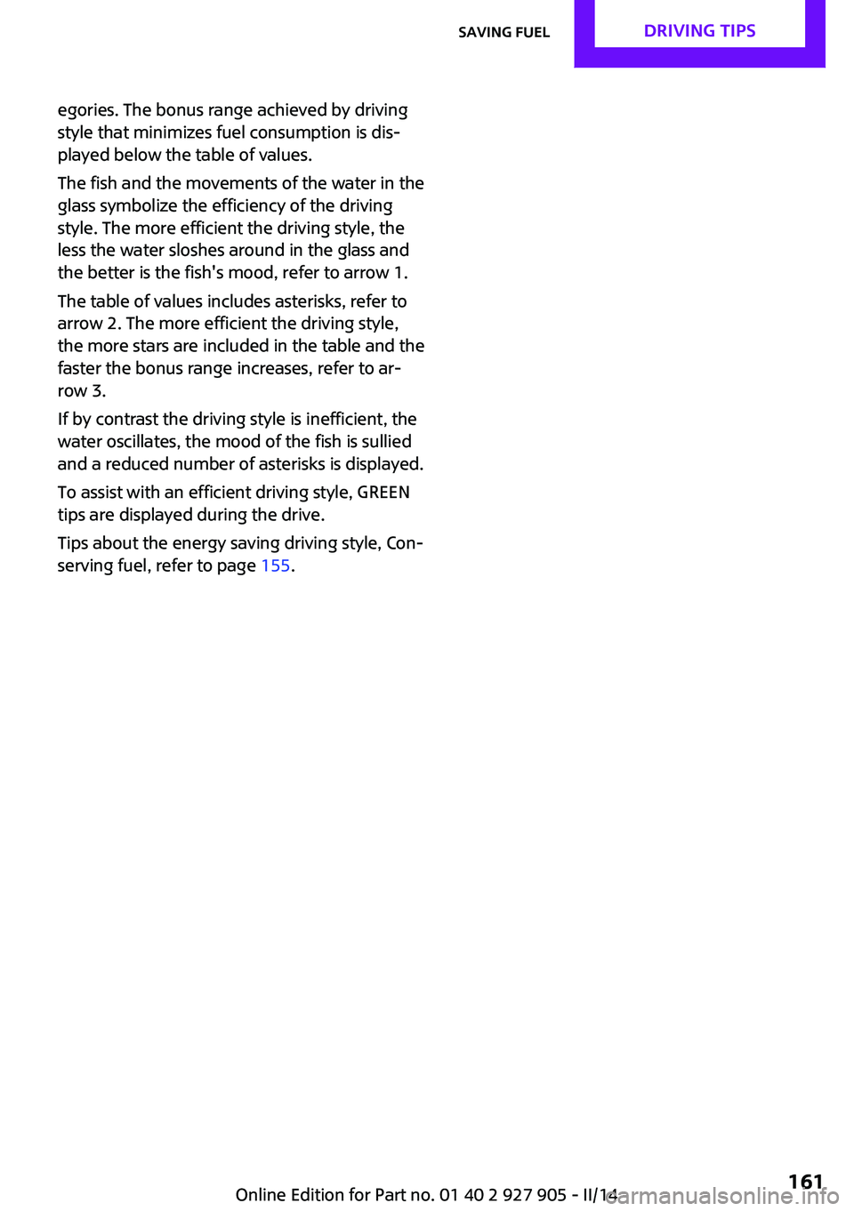
egories. The bonus range achieved by driving
style that minimizes fuel consumption is dis‐
played below the table of values.
The fish and the movements of the water in the
glass symbolize the efficiency of the driving
style. The more efficient the driving style, the
less the water sloshes around in the glass and
the better is the fish's mood, refer to arrow 1.
The table of values includes asterisks, refer to
arrow 2. The more efficient the driving style,
the more stars are included in the table and the
faster the bonus range increases, refer to ar‐
row 3.
If by contrast the driving style is inefficient, the
water oscillates, the mood of the fish is sullied
and a reduced number of asterisks is displayed.
To assist with an efficient driving style, GREEN
tips are displayed during the drive.
Tips about the energy saving driving style, Con‐
serving fuel, refer to page 155.Seite 161Saving fuelDRIVING TIPS161
Online Edition for Part no. 01 40 2 927 905 - II/14
Page 168 of 230
Wheels and tiresVehicle equipment
All standard, country-specific and optional
equipment that is offered in the model series is
described in this chapter. Therefore, equipment
is also described that is not available in a vehi‐
cle, e. g., because of the selected optional
equipment or country variant. This also applies
for safety-related functions and systems.
Tire inflation pressure
Safety information The tire characteristics and tire inflation pres‐
sure influence the following:▷The service life of the tires.▷Road safety.▷Driving comfort.
Checking the pressure
Tires have a natural, consistent loss of pressure.
Check the tire inflation pressure regularly
Regularly check the tire inflation pressure,
and correct it as needed: at least twice a month
and before a long trip. If you fail to observe this
precaution, you may be driving on tires with in‐
correct tire pressures, a condition that may not
only compromise your vehicle's driving stabil‐
ity, but also lead to tire damage and the risk of
an accident. ◀
Tires heat up during driving, and the tire infla‐
tion pressure increases along with the temper‐
ature of the tire. The tire inflation pressure
specifications relate to cold tires or tires with
the ambient temperature.
Only check the tire inflation pressure when the
tires are cold. This means after driving no more
than 1.25 miles/2 km or when the vehicle has
been parked for at least 2 hours.
The displays of inflation devices may under-
read by up to 0.1bar, 2psi.
For Flat Tire Monitor: after correcting the tire
inflation pressure, reinitialize the Flat Tire Moni‐
tor.
For Tire Pressure Monitor: after correcting the
tire inflation pressure, reset the Tire Pressure
Monitor.▷Reinitialize the Flat Tire Monitor.▷Reinitialize the Tire Pressure Monitor.
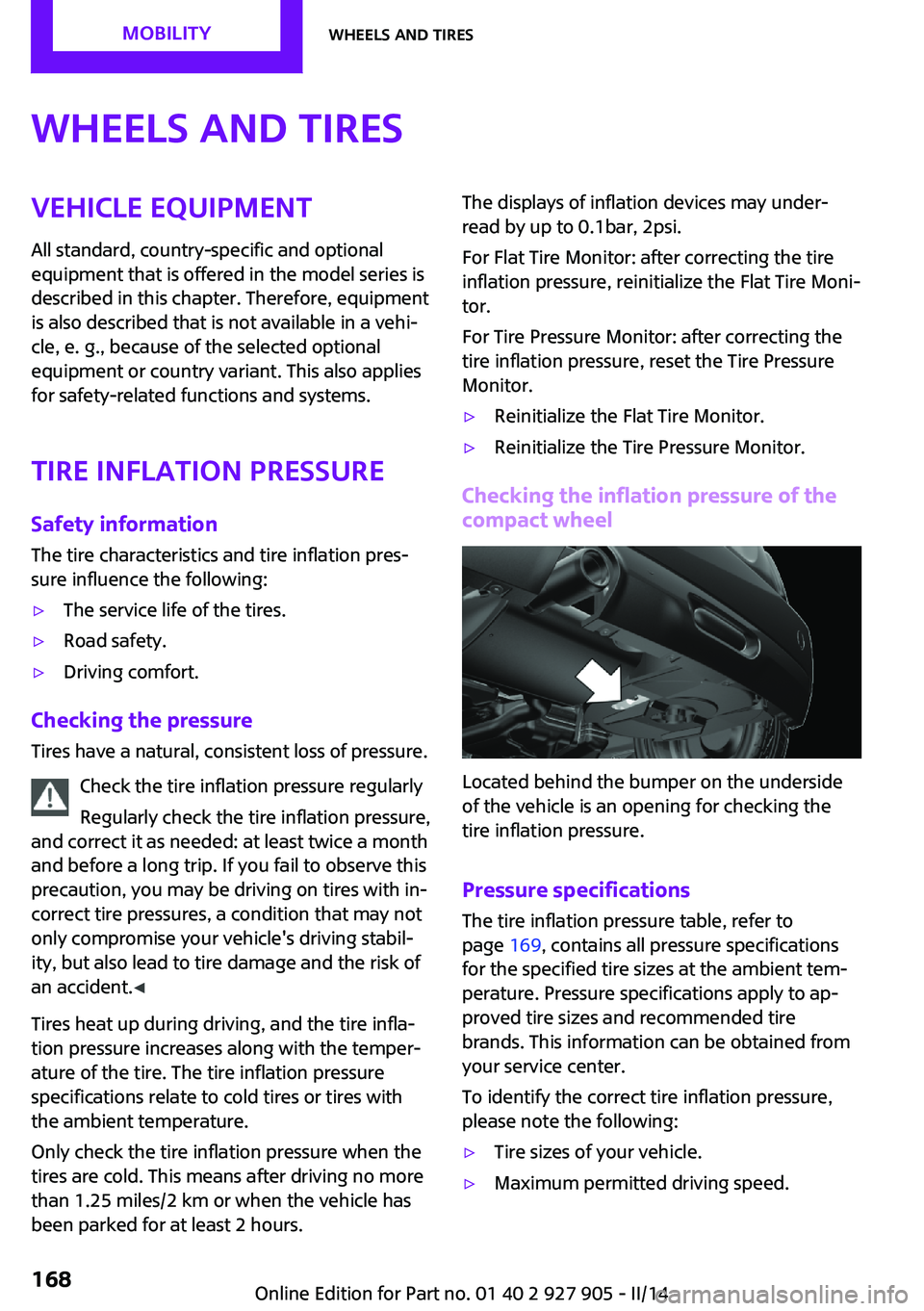
Checking the inflation pressure of the
compact wheel
Located behind the bumper on the underside
of the vehicle is an opening for checking the
tire inflation pressure.
Pressure specifications
The tire inflation pressure table, refer to
page 169, contains all pressure specifications
for the specified tire sizes at the ambient tem‐
perature. Pressure specifications apply to ap‐
proved tire sizes and recommended tire
brands. This information can be obtained from
your service center.
To identify the correct tire inflation pressure,
please note the following:
▷Tire sizes of your vehicle.▷Maximum permitted driving speed.Seite 168MOBILITYWheels and tires168
Online Edition for Part no. 01 40 2 927 905 - II/14