fog light MINI COOPER 2015 User Guide
[x] Cancel search | Manufacturer: MINI, Model Year: 2015, Model line: COOPER, Model: MINI COOPER 2015Pages: 248, PDF Size: 5.43 MB
Page 125 of 248
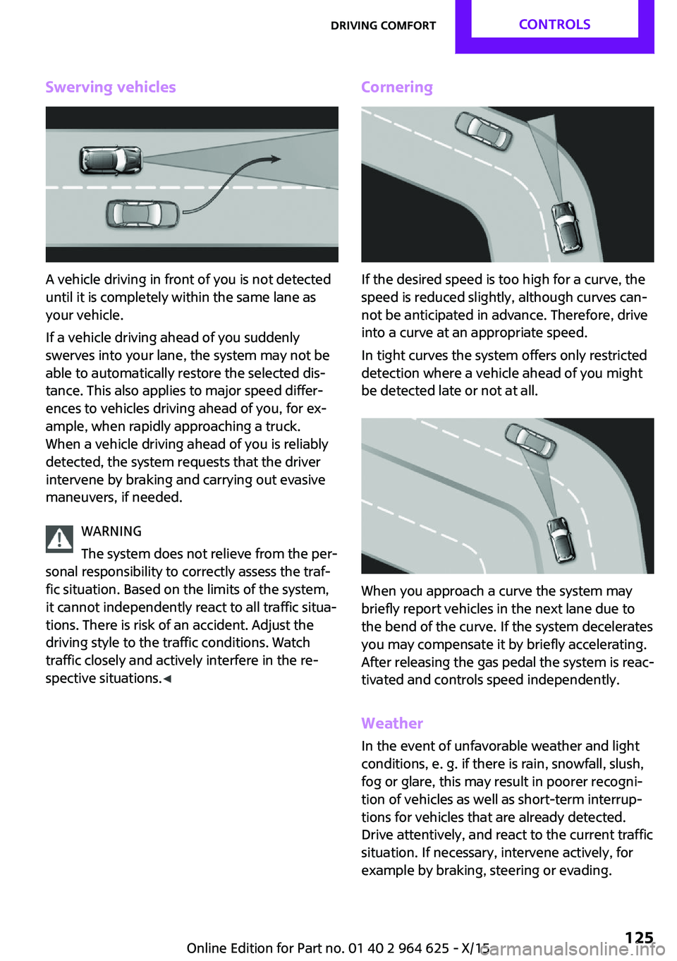
Swerving vehicles
A vehicle driving in front of you is not detected
until it is completely within the same lane as
your vehicle.
If a vehicle driving ahead of you suddenly
swerves into your lane, the system may not be
able to automatically restore the selected dis‐
tance. This also applies to major speed differ‐
ences to vehicles driving ahead of you, for ex‐
ample, when rapidly approaching a truck.
When a vehicle driving ahead of you is reliably
detected, the system requests that the driver
intervene by braking and carrying out evasive
maneuvers, if needed.
WARNING
The system does not relieve from the per‐
sonal responsibility to correctly assess the traf‐
fic situation. Based on the limits of the system,
it cannot independently react to all traffic situa‐
tions. There is risk of an accident. Adjust the
driving style to the traffic conditions. Watch
traffic closely and actively interfere in the re‐
spective situations. ◀
Cornering
If the desired speed is too high for a curve, the
speed is reduced slightly, although curves can‐
not be anticipated in advance. Therefore, drive
into a curve at an appropriate speed.
In tight curves the system offers only restricted
detection where a vehicle ahead of you might
be detected late or not at all.
When you approach a curve the system may
briefly report vehicles in the next lane due to
the bend of the curve. If the system decelerates
you may compensate it by briefly accelerating.
After releasing the gas pedal the system is reac‐
tivated and controls speed independently.
Weather
In the event of unfavorable weather and light conditions, e. g. if there is rain, snowfall, slush,
fog or glare, this may result in poorer recogni‐
tion of vehicles as well as short-term interrup‐
tions for vehicles that are already detected.
Drive attentively, and react to the current traffic
situation. If necessary, intervene actively, for
example by braking, steering or evading.
Seite 125Driving comfortCONTROLS125
Online Edition for Part no. 01 40 2 964 625 - X/15
Page 126 of 248
MalfunctionA Check Control message is displayed if the sys‐
tem fails or was automatically deactivated.
The system may not be fully functional in the
following situations:▷When an object was not correctly detected.▷In heavy fog, rain, sprayed water or snow‐
fall.▷In tight curves.▷If the field of view of the camera or the
front windshield are dirty or covered.▷When driving toward bright lights.▷Up to 20 seconds after the start of the en‐
gine, via the Start/Stop button.▷During calibration of the camera immedi‐
ately after vehicle delivery.
Cruise control
The concept
The system is functional at speeds beginning at
approx. 20 mph/30 km/h.
It maintains the speed that was set using the
control elements on the steering wheel.
The system brakes on downhill gradients if en‐
gine braking is insufficient.
Information WARNING
The system does not relieve from the per‐
sonal responsibility to correctly assess the traf‐
fic situation. Based on the limits of the system,
it cannot independently react to all traffic situa‐
tions. There is risk of an accident. Adjust the
driving style to the traffic conditions. Watch
traffic closely and actively interfere in the re‐
spective situations. ◀
WARNING
The use of the system can lead to an in‐
creased risk of accidents in the following situa‐
tions:▷On winding roads.▷In heavy traffic.▷On slippery roads, in fog, snow or rain, or
on a loose road surface.
There is risk of accidents or risk of property
damage. Only use the system if driving at con‐
stant speed is possible. ◀
General information Depending on the driving program, refer to
page 118, set, the characteristics of the cruise
control in particular areas can change.
Overview
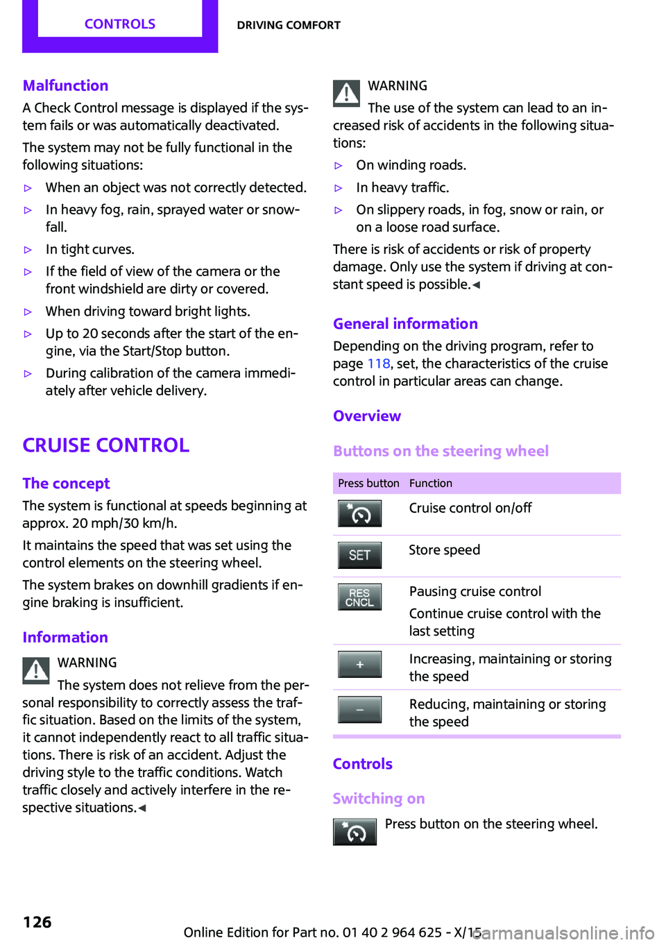
Buttons on the steering wheel
Press buttonFunctionCruise control on/offStore speedPausing cruise control
Continue cruise control with the
last settingIncreasing, maintaining or storing
the speedReducing, maintaining or storing
the speed
Controls
Switching on Press button on the steering wheel.
Seite 126CONTROLSDriving comfort126
Online Edition for Part no. 01 40 2 964 625 - X/15
Page 165 of 248
Roof racks are available as special accessories.Securing
Follow the installation instructions of the roof
rack.
Loading
Because roof racks raise the vehicle's center of
gravity when loaded, they have a major effect
on vehicle handling and steering response.
Therefore, note the following when loading and
driving:▷Do not exceed the approved roof/axle
loads and the approved gross vehicle
weight.▷Be sure that adequate clearance is main‐
tained for tilting and opening the glass sun‐
roof.▷Distribute the roof load uniformly.▷The roof load should not extend past the
loading area.▷Always place the heaviest pieces on the
bottom.▷Secure the roof luggage firmly, e.g., tie with
ratchet straps.▷Do not let objects project into the opening
path of the tailgate.▷Drive cautiously and avoid sudden acceler‐
ation and braking maneuvers. Take corners
gently.
Rear luggage rack
General information Installation only possible with rear luggage rack
preparation.
Rear racks are available as special accessories.
Information Follow the installation instructions of the rear
luggage rack.
Drive cautiously and avoid sudden acceleration
and braking maneuvers. Take corners gently.
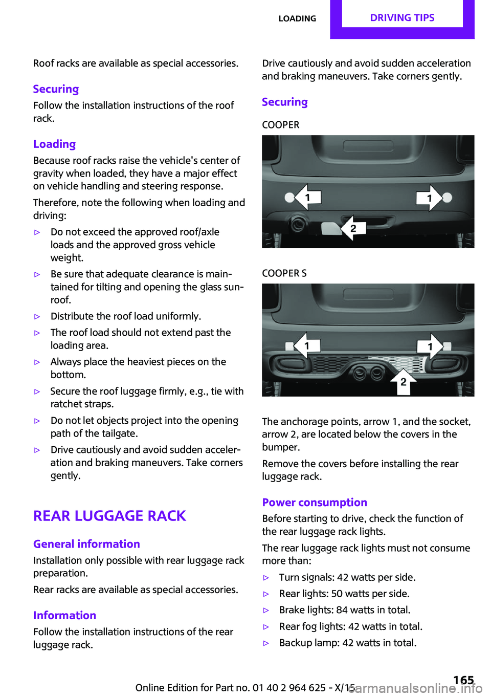
SecuringCOOPERCOOPER S
The anchorage points, arrow 1, and the socket,
arrow 2, are located below the covers in the
bumper.
Remove the covers before installing the rear
luggage rack.
Power consumption
Before starting to drive, check the function of
the rear luggage rack lights.
The rear luggage rack lights must not consume
more than:
▷Turn signals: 42 watts per side.▷Rear lights: 50 watts per side.▷Brake lights: 84 watts in total.▷Rear fog lights: 42 watts in total.▷Backup lamp: 42 watts in total.Seite 165LoadingDRIVING TIPS165
Online Edition for Part no. 01 40 2 964 625 - X/15
Page 206 of 248

Front lights, bulb replacement
Overview
Halogen headlights1Low beams/high beams2Turn signal
LED headlights
1Daytime running lights2Low beams/high beams3Turn signalBug light1Parking lights2Daytime running lights3Fog lights
LED bug light
1Parking lights2Fog lights
LED low beams/LED high beams Follow the general instructions on lights and
bulbs, refer to page 205.
The lights feature LED technology. In the case
of a malfunction, contact a dealer’s service cen‐
ter or another qualified service center or repair
shop.
Halogen low beams/halogen high
beams
Follow the general instructions on lights and
bulbs, refer to page 205.
Seite 206MOBILITYReplacing components206
Online Edition for Part no. 01 40 2 964 625 - X/15
Page 208 of 248
LED parking lights/LED fog lightsFollow the general instructions on lights and
bulbs, refer to page 205.
The lights feature LED technology. In the case
of a malfunction, contact a dealer’s service cen‐
ter or another qualified service center or repair
shop.
Parking lights/fog lights/daytime
running lights
Follow the general instructions on lights and
bulbs, refer to page 205.
Bulbs:▷Parking lights for halogen headlights: W5W
Parking lights for LED headlights: W5W NBV▷Daytime running light: PSX24W▷Fog lamp: H8
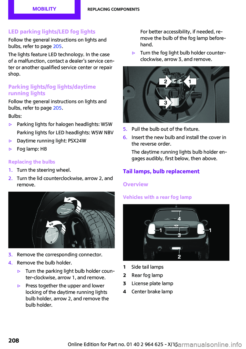
Replacing the bulbs
1.Turn the steering wheel.2.Turn the lid counterclockwise, arrow 2, and
remove.3.Remove the corresponding connector.4.Remove the bulb holder.▷Turn the parking light bulb holder coun‐
ter-clockwise, arrow 1, and remove.▷Press together the upper and lower
locking of the daytime running lights
bulb holder, arrow 2, and remove the
bulb holder.For better accessibility, if needed, re‐
move the bulb of the fog lamp before‐
hand.▷Turn the fog light bulb holder counter-
clockwise, arrow 3, and remove.5.Pull the bulb out of the fixture.6.Insert the new bulb and install the cover in
the reverse order.
The daytime running lights bulb holder en‐
gages audibly, first below, then above.
Tail lamps, bulb replacement
Overview
Vehicles with a rear fog lamp
1Side tail lamps2Rear fog lamp3License plate lamp4Center brake lampSeite 208MOBILITYReplacing components208
Online Edition for Part no. 01 40 2 964 625 - X/15
Page 209 of 248
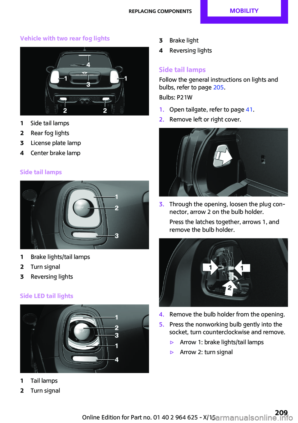
Vehicle with two rear fog lights1Side tail lamps2Rear fog lights3License plate lamp4Center brake lamp
Side tail lamps
1Brake lights/tail lamps2Turn signal3Reversing lights
Side LED tail lights
1Tail lamps2Turn signal3Brake light4Reversing lights
Side tail lampsFollow the general instructions on lights and
bulbs, refer to page 205.
Bulbs: P21W
1.Open tailgate, refer to page 41.2.Remove left or right cover.3.Through the opening, loosen the plug con‐
nector, arrow 2 on the bulb holder.
Press the latches together, arrows 1, and
remove the bulb holder.4.Remove the bulb holder from the opening.5.Press the nonworking bulb gently into the
socket, turn counterclockwise and remove.▷Arrow 1: brake lights/tail lamps▷Arrow 2: turn signalSeite 209Replacing componentsMOBILITY209
Online Edition for Part no. 01 40 2 964 625 - X/15
Page 210 of 248
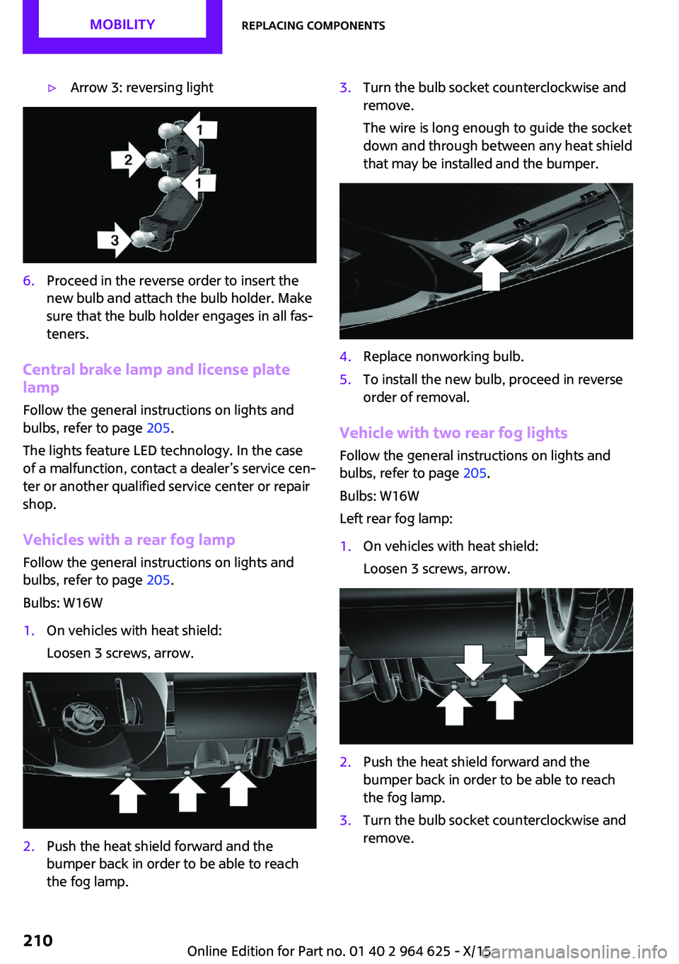
▷Arrow 3: reversing light6.Proceed in the reverse order to insert the
new bulb and attach the bulb holder. Make
sure that the bulb holder engages in all fas‐
teners.
Central brake lamp and license plate
lamp
Follow the general instructions on lights and
bulbs, refer to page 205.
The lights feature LED technology. In the case
of a malfunction, contact a dealer’s service cen‐
ter or another qualified service center or repair
shop.
Vehicles with a rear fog lamp Follow the general instructions on lights and
bulbs, refer to page 205.
Bulbs: W16W
1.On vehicles with heat shield:
Loosen 3 screws, arrow.2.Push the heat shield forward and the
bumper back in order to be able to reach
the fog lamp.3.Turn the bulb socket counterclockwise and
remove.
The wire is long enough to guide the socket
down and through between any heat shield
that may be installed and the bumper.4.Replace nonworking bulb.5.To install the new bulb, proceed in reverse
order of removal.
Vehicle with two rear fog lights
Follow the general instructions on lights and
bulbs, refer to page 205.
Bulbs: W16W
Left rear fog lamp:
1.On vehicles with heat shield:
Loosen 3 screws, arrow.2.Push the heat shield forward and the
bumper back in order to be able to reach
the fog lamp.3.Turn the bulb socket counterclockwise and
remove.Seite 210MOBILITYReplacing components210
Online Edition for Part no. 01 40 2 964 625 - X/15
Page 211 of 248
The wire is long enough to guide the socket
down and through between any heat shield
that may be installed and the bumper.4.Replace nonworking bulb.5.To install the new bulb, proceed in reverse
order of removal.
Right fog lamp:
1.Turn the bulb socket counterclockwise and
remove.
The wire is long enough to guide the socket
down and through between any heat shield
that may be installed and the bumper.2.Replace nonworking bulb.3.To install the new bulb, proceed in reverse
order of removal.
Side turn signal, bulb replacement
Follow the general instructions on lights and
bulbs, refer to page 205.
Bulbs:
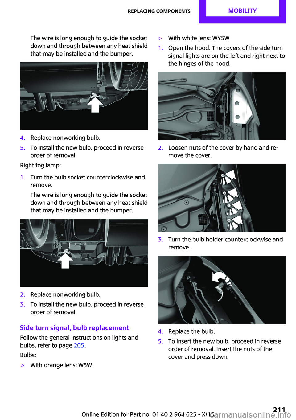
▷With orange lens: W5W▷With white lens: WY5W1.Open the hood. The covers of the side turn
signal lights are on the left and right next to
the hinges of the hood.2.Loosen nuts of the cover by hand and re‐
move the cover.3.Turn the bulb holder counterclockwise and
remove.4.Replace the bulb.5.To insert the new bulb, proceed in reverse
order of removal. Insert the nuts of the
cover and press down.Seite 211Replacing componentsMOBILITY211
Online Edition for Part no. 01 40 2 964 625 - X/15
Page 240 of 248

Direction indicator, see Turnsignals 67
Display, electronic, instrument cluster 77
Display, engine tempera‐ ture 86
Display lighting, see Instru‐ ment lighting 98
Displays 76
Displays, cleaning 224
Disposal, coolant 201
Disposal, vehicle battery 215
Distance control, see PDC 128
Distance to destination 86
Divided screen view, split screen 23
Door lock, see Remote con‐ trol 34
Drive mode, GREEN Mode 167
Drive-off assistant 119
Drive-off assistant, see DSC 116
Driving Dynamics Control 118
Driving Excitement, SPORT 87
Driving instruction, GREEN Mode 169
Driving instructions, break- in 160
Driving mode 118
Driving notes, general 161
Driving stability control sys‐ tems 116
Driving style analysis 171
Driving tips 161
DSC Dynamic Stability Con‐ trol 116
DTC Dynamic Traction Con‐ trol 117
Dynamic Damping Con‐ trol 118
Dynamic Stability Control DSC 116
Dynamic Traction Control DTC 117 E
Electronic displays, instrument cluster 77
Electronic oil measure‐ ment 196
Electronic Stability Program ESP, see DSC 116
Emergency detection, remote control 35
Emergency release, fuel filler flap 176
Emergency start function, en‐ gine start 35
Emergency wheel, compact wheel, see Emergency
wheel 212
Energy Control 82
Engine, automatic Start/Stop function 64
Engine, automatic switch- off 64
Engine compartment 194
Engine compartment, working in 194
Engine coolant 200
Engine idling when driving, coasting 170
Engine oil 196
Engine oil, adding 197
Engine oil additives 198
Engine oil change 198
Engine oil filler neck 197
Engine oil types, alterna‐ tive 198
Engine oil types, suitable 198
Engine start during malfunc‐ tion 35
Engine start, jump-start‐ ing 216
Engine start, see Starting the engine 63
Engine stop 63
Engine temperature, dis‐ play 86
Entering a car wash 221 Equipment, interior 145
Error displays, see Check Con‐ trol 77
ESP Electronic Stability Pro‐ gram, see DSC 116
Exchanging wheels/tires 188
Exhaust system 161
Exterior mirror, automatic dimming feature 56
Exterior mirrors 55
External start 216
External temperature dis‐ play 81
External temperature warn‐ ing 81
Eyes for securing cargo 164
F
Failure message, see Check Control 77
False alarm, see Unintentional alarm 45
Fan, see Air flow 139, 142
Favorites buttons, onboard monitor 24
Filler neck for engine oil 197
Fine wood, care 223
First-aid kit 216
Flat tire, changing wheels 212
Flat Tire Monitor FTM 107
Flat tire, repairing 190
Flat tire, Tire Pressure Monitor TPM 103
Flat tire, warning lamp 104, 107
Flooding 161
Floor carpet, care 224
Floor mats, care 224
Fogged up windows 140
Folding back rear seat back‐ rests 151
Fold-out position, windshield wipers 70
Foot brake 161
Front airbags 100 Seite 240REFERENCEEverything from A to Z240
Online Edition for Part no. 01 40 2 964 625 - X/15
Page 241 of 248

Front-end collision warningwith City Braking func‐
tion 110
Front fog lights 98
Front-seat passenger airbags, automatic deactivation 102
Front-seat passenger airbags, indicator lamp 102
FTM Flat Tire Monitor 107
Fuel 178
Fuel consumption, see Aver‐ age fuel consumption 86
Fuel filler flap 176
Fuel gauge 81
Fuel lid 176
Fuel quality 178
Fuel recommendation 178
Fuel, tank capacity 232
Fuse 215
G Garage door opener, see Uni‐ versal Integrated Remote
Control 145
Gasoline 178
Gear change, Steptronic trans‐ mission 72
Gear shift indicator 83
General driving notes 161
Glare shield 149
Glass sunroof, refer to Panor‐ amic glass sunroof 47
Glove compartment 153
GREEN Mode 167
GREEN Mode, bonus range 169
GREEN Mode driving style analysis 171
GREEN Mode indicator 167
GREEN - program, driving dy‐ namics 118
GREEN tip 169
Gross vehicle weight, ap‐ proved 229
Ground clearance 162 H
Halogen headlights 206
Handbrake, see parking brake 66
Hand-held transmitter, alter‐ nating code 146
Hazard warning flashers 216
Head airbag 100
Headlight control, auto‐ matic 96
Headlight courtesy delay fea‐ ture 96
Headlight flasher 68
Headlight glass 205
Headlights, care 222
Head restraints 49
Head restraints, front 53
Head restraints, rear 54
Head-up Display 90
Head-Up Display, Shift point indicator 92
Head-up Display, sport dis‐ plays 92
Head-up Display, standard view 91
Heavy cargo, stowing 164
High-beam Assistant 97
High beams 68
High beams/low beams, see High-beam Assistant 97
Hills 162
Hill start assistant, see Drive- off assistant 119
Holder for beverages 154
Homepage 6
Hood 194
Horn 14
Hot exhaust system 161
HUD Head-up Display 90
Hydroplaning 161
I
Ice warning, see External tem‐ perature warning 81 Icy roads, see External tem‐
perature warning 81
Identification marks, tires 186
Identification number, see ve‐ hicle identification num‐
ber 10
Ignition key, see Remote con‐ trol 34
Ignition off 62
Ignition on 62
Illuminated ring, central in‐ strument cluster 89
Indication of a flat tire 104, 107
Indicator lamp, see Check Control 77
Individual air distribu‐ tion 139, 142
Individual settings, see Per‐ sonal Profile 36
Inflation pressure, tires 180
Inflation pressure warning, tires 107
Info display, refer to On-Board computer 85
Information 6
Initialize, Tire Pressure Moni‐ tor TPM 104
Initializing, Flat Tire Monitor FTM 107
Instrument cluster 76
Instrument cluster, electronic displays 77
Instrument lighting 98
Integrated key 34
Integrated Owner's Manual in the vehicle 29
Intelligent Safety 109
Intensity, AUTO program 142
Interior equipment 145
Interior lights 98
Interior lights during unlock‐ ing 37
Interior lights with the vehicle locked 38 Seite 241Everything from A to ZREFERENCE241
Online Edition for Part no. 01 40 2 964 625 - X/15