top up MINI COOPER 2015 Owner's Manual
[x] Cancel search | Manufacturer: MINI, Model Year: 2015, Model line: COOPER, Model: MINI COOPER 2015Pages: 248, PDF Size: 5.43 MB
Page 66 of 248

▷Steptronic transmission: change from selec‐
tor lever position P to R, N, D or M/S.▷The vehicle begins rolling.▷Fogging of the windows when the auto‐
matic climate control is switched on.▷The vehicle battery charge is very low.▷Excessive cooling of the car's interior when
the heating is switched on.▷Manual transmission: low brake vacuum
pressure; this can occur, for example, if the
brake pedal is depressed a number of times
in succession.
Switching the system on/off
Using the button
Press button.
▷LED comes on: Auto Start/Stop function is
deactivated.
The engine is started during an automatic
engine stop.
The engine can only be stopped or started
via the Start/Stop button.▷LED goes out: Auto Start/Stop function is
activated.
Switching off the vehicle during an automatic engine stop
During an automatic engine stop, the vehicle
can be switched off permanently, e. g., when
leaving it.
Steptronic transmission:1.Engage selector lever position P.2.Press the Start/Stop button. The ignition is
switched off. The Auto Start/Stop function is
deactivated.3.Set the parking brake.
Manual transmission:
1.Press the Start/Stop button. The ignition is
switched off. The Auto Start/Stop function is
deactivated.2.Shift into first gear or reverse.3.Set the parking brake.
Engine start as usual via Start/Stop button.
Automatic deactivation
In certain situations, the Auto Start/Stop func‐
tion is deactivated automatically for safety rea‐
sons, as it is detected that no driver is present.
Malfunction The Auto Start/Stop function no longer switches
off the engine automatically. A Check Control
message is displayed. It is possible to continue
driving. Have the system checked by a dealer’s
service center or another qualified service cen‐
ter or repair shop.
Parking brake Information WARNING
An unsecured vehicle can put itself into
motion and roll away. There is risk of an acci‐
dent. Before exiting, secure the vehicle against
rolling.
In order to ensure that the vehicle is secured
against rolling away, observe the following:
▷Set the parking brake.▷On uphill grades or on a slope, turn the
front wheels in the direction of the curb.Seite 66CONTROLSDriving66
Online Edition for Part no. 01 40 2 964 625 - X/15
Page 78 of 248
be activated if objects are placed on the front
passenger seat.
Make sure that the safety belts are positioned
correctly.
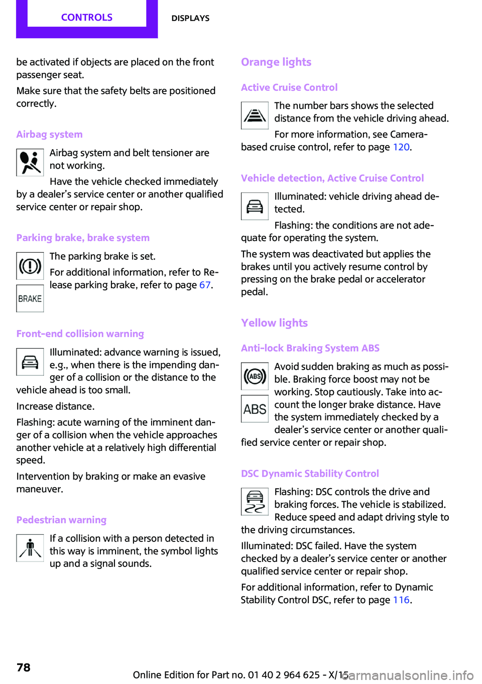
Airbag system Airbag system and belt tensioner are
not working.
Have the vehicle checked immediately
by a dealer’s service center or another qualified
service center or repair shop.
Parking brake, brake system The parking brake is set.
For additional information, refer to Re‐
lease parking brake, refer to page 67.
Front-end collision warning Illuminated: advance warning is issued,
e.g., when there is the impending dan‐
ger of a collision or the distance to the
vehicle ahead is too small.
Increase distance.
Flashing: acute warning of the imminent dan‐
ger of a collision when the vehicle approaches
another vehicle at a relatively high differential
speed.
Intervention by braking or make an evasive
maneuver.
Pedestrian warning If a collision with a person detected in
this way is imminent, the symbol lights
up and a signal sounds.Orange lights
Active Cruise Control The number bars shows the selected
distance from the vehicle driving ahead.
For more information, see Camera-
based cruise control, refer to page 120.
Vehicle detection, Active Cruise Control Illuminated: vehicle driving ahead de‐
tected.
Flashing: the conditions are not ade‐
quate for operating the system.
The system was deactivated but applies the
brakes until you actively resume control by
pressing on the brake pedal or accelerator
pedal.
Yellow lights Anti-lock Braking System ABS Avoid sudden braking as much as possi‐
ble. Braking force boost may not be
working. Stop cautiously. Take into ac‐
count the longer brake distance. Have
the system immediately checked by a
dealer’s service center or another quali‐
fied service center or repair shop.
DSC Dynamic Stability Control Flashing: DSC controls the drive and
braking forces. The vehicle is stabilized.
Reduce speed and adapt driving style to
the driving circumstances.
Illuminated: DSC failed. Have the system
checked by a dealer’s service center or another
qualified service center or repair shop.
For additional information, refer to Dynamic
Stability Control DSC, refer to page 116.Seite 78CONTROLSDisplays78
Online Edition for Part no. 01 40 2 964 625 - X/15
Page 79 of 248
DSC Dynamic Stability Control is deactivated
or DTC Dynamic Traction Control is activated
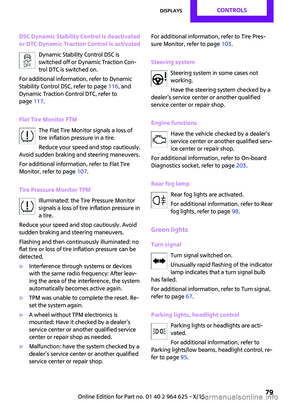
Dynamic Stability Control DSC is
switched off or Dynamic Traction Con‐
trol DTC is switched on.
For additional information, refer to Dynamic
Stability Control DSC, refer to page 116, and
Dynamic Traction Control DTC, refer to
page 117.
Flat Tire Monitor FTM The Flat Tire Monitor signals a loss of
tire inflation pressure in a tire.
Reduce your speed and stop cautiously.
Avoid sudden braking and steering maneuvers.
For additional information, refer to Flat Tire
Monitor, refer to page 107.
Tire Pressure Monitor TPM Illuminated: the Tire Pressure Monitor
signals a loss of tire inflation pressure in
a tire.
Reduce your speed and stop cautiously. Avoid
sudden braking and steering maneuvers.
Flashing and then continuously illuminated: no
flat tire or loss of tire inflation pressure can be
detected.▷Interference through systems or devices
with the same radio frequency: After leav‐
ing the area of the interference, the system
automatically becomes active again.▷TPM was unable to complete the reset. Re‐
set the system again.▷A wheel without TPM electronics is
mounted: Have it checked by a dealer’s
service center or another qualified service
center or repair shop as needed.▷Malfunction: have the system checked by a
dealer’s service center or another qualified
service center or repair shop.For additional information, refer to Tire Pres‐
sure Monitor, refer to page 103.
Steering system Steering system in some cases not
working.
Have the steering system checked by a
dealer’s service center or another qualified
service center or repair shop.
Engine functions Have the vehicle checked by a dealer’s
service center or another qualified serv‐
ice center or repair shop.
For additional information, refer to On-board
Diagnostics socket, refer to page 203.
Rear fog lamp Rear fog lights are activated.
For additional information, refer to Rear
fog lights, refer to page 98.
Green lights Turn signal Turn signal switched on.
Unusually rapid flashing of the indicator
lamp indicates that a turn signal bulb
has failed.
For additional information, refer to Turn signal,
refer to page 67.
Parking lights, headlight control Parking lights or headlights are acti‐
vated.
For additional information, refer to
Parking lights/low beams, headlight control, re‐
fer to page 95.Seite 79DisplaysCONTROLS79
Online Edition for Part no. 01 40 2 964 625 - X/15
Page 86 of 248

When destination guidance is activated in
the navigation system.▷Speed limit detection.▷Speed.
Selecting information
You can select what information from the on‐
board computer is to be displayed on the CID
(central information display) of the instrument
cluster.
On the Control Display:
1. "Settings"2."Instrument cluster"3.Select the desired information.
Settings are stored for the profile currently
used.
Information in detail
Range Displays the estimated cruising range available
with the remaining fuel.
It is calculated based on your driving style over
the last 20 miles/30 km.
GREEN info Description of GREEN info, refer to page 169.
Average fuel consumption This is calculated for the period while the en‐
gine is running.
The average fuel consumption is calculated for
the distance traveled since the last reset by the
onboard computer.
Average speed Periods in which the vehicle is parked with the
engine manually stopped are not included in
the calculation of the average speed.
Resetting average values
Press and hold button on turn signal lever.
Engine temperature display
Displays the current engine temperature, based
on a combination of coolant and motor oil tem‐
perature. As soon as the optimum operating
temperature has been attained, the indicator is
in the center position.
If the engine oil or coolant, thus the engine, be‐
come too hot, a Check Control message is dis‐
played.
Check the coolant level, refer to page 200.
With equipment version with Head-up
Display and navigation: distance to
destination
The distance remaining to the destination is
displayed if a destination is entered in the navi‐
gation system before the trip is started.
The distance to the destination is adopted au‐
tomatically.
With equipment version with Head-up
Display and navigation: time of arrival
The estimated time of arrival is displayed if a
destination is entered in the navigation system
before the trip is started.
The time must be correctly set.
Speed limit detection
Speed limit detection is preset. Description of
the speed limit detection, refer to page 83,
function.
Seite 86CONTROLSDisplays86
Online Edition for Part no. 01 40 2 964 625 - X/15
Page 93 of 248
Chrono package in the
cockpit
The concept
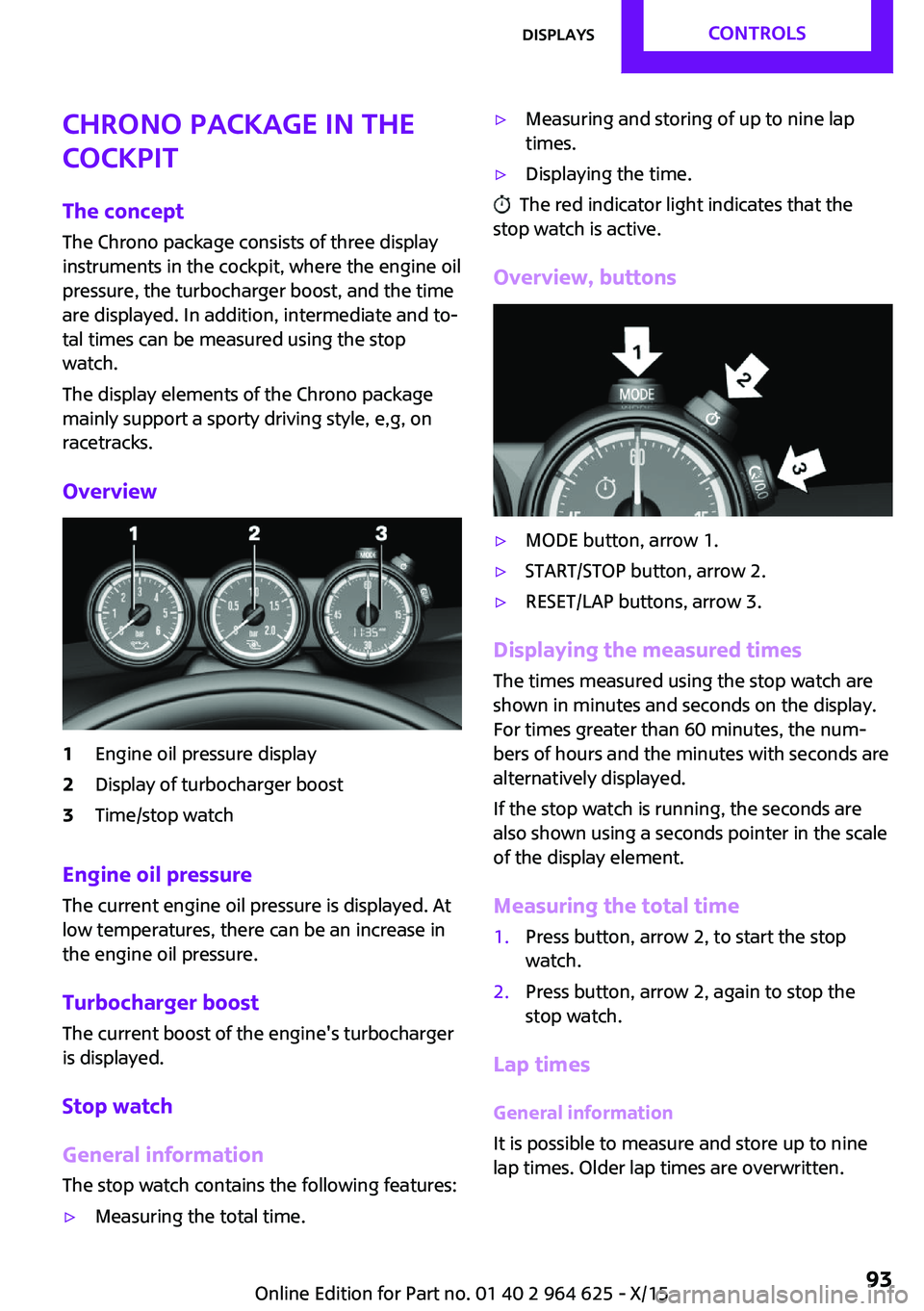
The Chrono package consists of three display
instruments in the cockpit, where the engine oil
pressure, the turbocharger boost, and the time
are displayed. In addition, intermediate and to‐
tal times can be measured using the stop
watch.
The display elements of the Chrono package
mainly support a sporty driving style, e,g, on
racetracks.
Overview1Engine oil pressure display2Display of turbocharger boost3Time/stop watch
Engine oil pressure
The current engine oil pressure is displayed. At
low temperatures, there can be an increase in
the engine oil pressure.
Turbocharger boostThe current boost of the engine's turbocharger
is displayed.
Stop watch
General information The stop watch contains the following features:
▷Measuring the total time.▷Measuring and storing of up to nine lap
times.▷Displaying the time.
The red indicator light indicates that the
stop watch is active.
Overview, buttons
▷MODE button, arrow 1.▷START/STOP button, arrow 2.▷RESET/LAP buttons, arrow 3.
Displaying the measured times
The times measured using the stop watch are
shown in minutes and seconds on the display.
For times greater than 60 minutes, the num‐ bers of hours and the minutes with seconds are
alternatively displayed.
If the stop watch is running, the seconds are
also shown using a seconds pointer in the scale
of the display element.
Measuring the total time
1.Press button, arrow 2, to start the stop
watch.2.Press button, arrow 2, again to stop the
stop watch.
Lap times
General information
It is possible to measure and store up to nine
lap times. Older lap times are overwritten.
Seite 93DisplaysCONTROLS93
Online Edition for Part no. 01 40 2 964 625 - X/15
Page 94 of 248
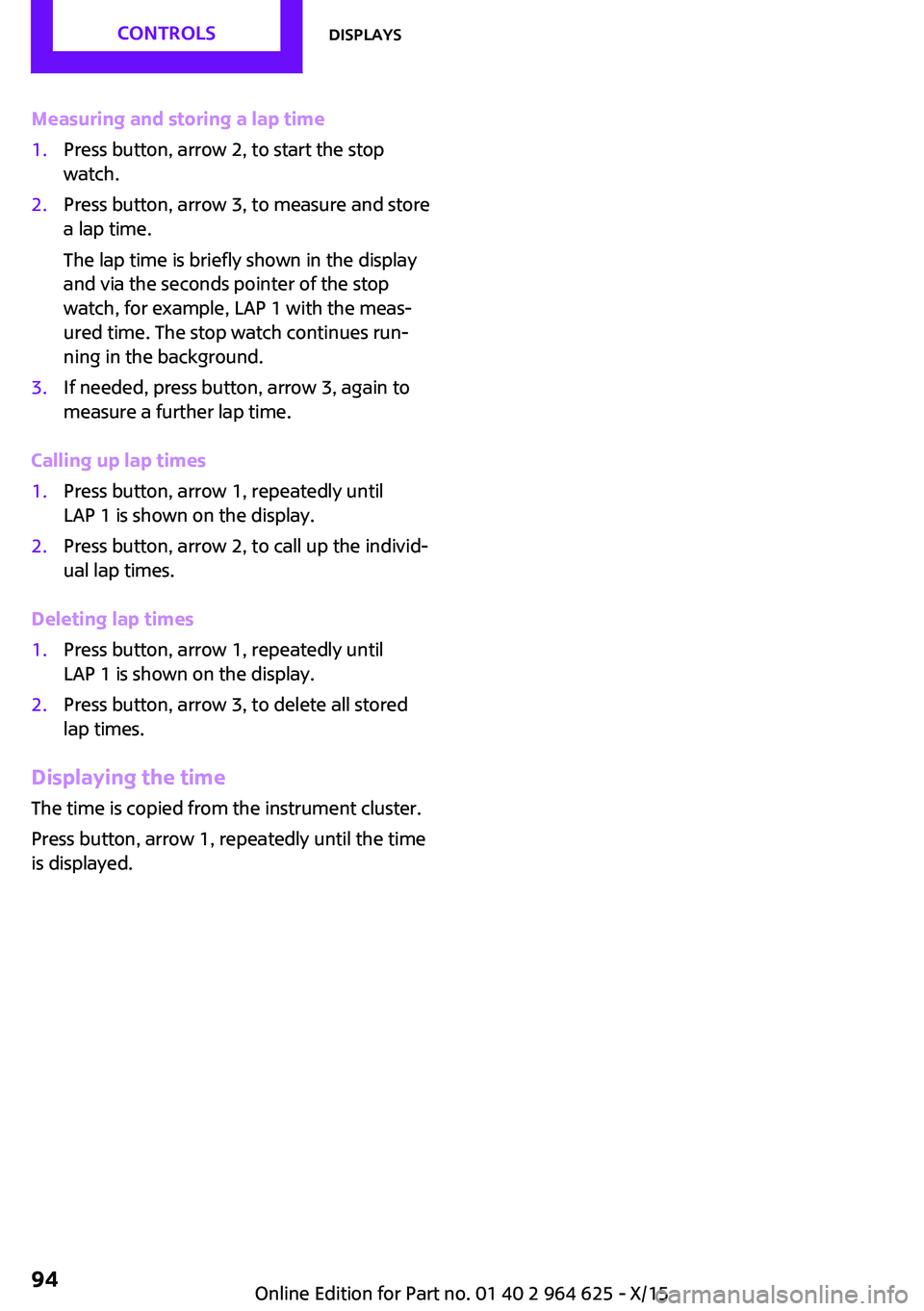
Measuring and storing a lap time1.Press button, arrow 2, to start the stop
watch.2.Press button, arrow 3, to measure and store
a lap time.
The lap time is briefly shown in the display
and via the seconds pointer of the stop
watch, for example, LAP 1 with the meas‐
ured time. The stop watch continues run‐
ning in the background.3.If needed, press button, arrow 3, again to
measure a further lap time.
Calling up lap times
1.Press button, arrow 1, repeatedly until
LAP 1 is shown on the display.2.Press button, arrow 2, to call up the individ‐
ual lap times.
Deleting lap times
1.Press button, arrow 1, repeatedly until
LAP 1 is shown on the display.2.Press button, arrow 3, to delete all stored
lap times.
Displaying the time
The time is copied from the instrument cluster.
Press button, arrow 1, repeatedly until the time
is displayed.
Seite 94CONTROLSDisplays94
Online Edition for Part no. 01 40 2 964 625 - X/15
Page 98 of 248
When the low beams are on, the lights are au‐
tomatically brightened or dimmed.
The blue indicator lamp in the instru‐
ment cluster lights up when the system
switches on the high beams.
Deactivating The High-beam Assistant is deactivated when
manually switching the high beams on and off,
refer to page 68.
To reactivate the High-beam Assistant, press
the button on the turn signal lever.
System limits The High-beam Assistant cannot serve as a
substitute for the driver's personal judgment of when to use the high beams. Therefore, man‐
ually switch off the high beams in situations
where required to avoid a safety risk.
The system is not fully functional in the follow‐
ing situations, and driver intervention may be
necessary:▷In very unfavorable weather conditions,
such as fog or heavy precipitation.▷When detecting poorly-lit road users such
as pedestrians, cyclists, horseback riders
and wagons; when driving close to train or
ship traffic; and at animal crossings.▷In tight curves, on hilltops or in depressions,
in cross traffic or half-obscured oncoming
traffic on highways.▷In poorly-lit towns and cities and in the
presence of highly reflective signs.▷When the windshield behind the interior
mirror is fogged over, dirty or covered with
stickers, etc.
Fog lights
Front fog lights
The low beams must be switched on.
Press button. The green indicator lamp
lights up.
If the automatic headlight control, refer to
page 96, is activated, the low beams will come
on automatically when you switch on the front
fog lights.
When the high beams or headlight flasher are
activated, the front fog lights are not switched
on.
Rear fog lights
The low beams or front fog lights must be
switched on.
Press button. The yellow indicator
lamp lights up.
If the automatic headlight control, refer to
page 96, is activated, the low beams will come
on automatically when you switch on the rear
fog lights.
Instrument lightingAdjusting The parking lights or low beams
must be switched on to adjust
the brightness.
Adjust the brightness with the
thumbwheel.
Interior lights General information
The interior lights, footwell lights, access lights
and courtesy lights are controlled automati‐
cally.
Thumb wheel for the instrument lighting con‐
trols brightness of some of these features.Seite 98CONTROLSLights98
Online Edition for Part no. 01 40 2 964 625 - X/15
Page 104 of 248

Status displayThe current status of the Tire Pressure Monitor
TPM can be displayed on the Control Display,
e.g., whether or not the TPM is active.
On the Control Display:1. "Vehicle info"2."Vehicle status"3. "Tire Pressure Monitor (TPM)"
The status is displayed.
Status control display Tire and system status are indicated by the
color of the tires and a text message on the
Control Display.
All wheels green System is active and will issue a warning rela‐
tive to the tire inflation pressures stored during
the last reset.
One wheel is yellowA flat tire or major drop in inflation pressure in
the indicated tire.
All wheels are yellow A flat tire or major drop in inflation pressure in
several tires.
Wheels, gray
The system cannot detect a flat tire due to a
malfunction.
Status information The status control display additionally shows
the current tire inflation pressures. It shows the
actual values read; they may vary depending
on driving style or weather conditions.
Carry out reset
Reset the system after each adjustment of the
tire inflation pressure and after every tire or
wheel change.
On the Control Display and on the vehicle:1. "Vehicle info"2."Vehicle status"3. "Perform reset"4.Start the engine - do not drive off.5.Reset the tire inflation pressure using
"Perform reset".6.Drive away.
The tires are shown in gray and the status is
displayed.
After driving faster than 19 mph/30 km/h for a
short period, the set tire inflation pressures are
accepted as reference values. The resetting
process is completed automatically while driv‐
ing. After successful completion of the reset,
the tires appear in green on the Control Display
and "Tire Pressure Monitor (TPM) active" is dis‐ played.
The progress of the reset is displayed.
You may interrupt this trip at any time. When
you continue the reset resumes automatically.
Low tire pressure message The yellow warning lamp lights up. A
Check Control message is displayed.
▷There is a flat tire or a major loss in
tire inflation pressure.▷A reset of the system was not carried out
after a wheel was changed. The system
therefore issues a warning based on the tire
pressures before the last reset.1.Reduce your speed and stop cautiously.
Avoid sudden braking and steering maneu‐
vers.2.Check whether the vehicle is fitted with
normal tires or run-flat tires.
Run-flat tires, refer to page 190, are la‐
beled with a circular symbol containing the
letters RSC marked on the tire's sidewall.Seite 104CONTROLSSafety104
Online Edition for Part no. 01 40 2 964 625 - X/15
Page 106 of 248
Final tire failure
Vibrations or loud noises while driving can indi‐
cate the final failure of a tire.
Reduce speed and stop; otherwise, pieces of
the tire could come loose and cause an acci‐
dent.
Do not continue driving. Contact a dealer’s
service center or another qualified service cen‐
ter or repair shop.
Required inflation pressure check
message
A Check Control message is displayed in the fol‐
lowing situations▷The system has detected a wheel change,
but no reset was done.▷Inflation was not carried out according to
specifications.▷The tire inflation pressure has fallen below
the level of the last confirmation.
In this case:
▷Check the tire pressure and correct as
needed.▷Carry out a reset of the system after a tire
change.
System limits
The system does not function properly if a reset
has not been carried out, e.g., a flat tire is re‐
ported though tire inflation pressures are cor‐
rect.
The tire inflation pressure depends on the tire's
temperature. Driving or exposure to the sun
will increase the tire's temperature, thus in‐
creasing the tire inflation pressure. The tire in‐
flation pressure is reduced when the tire tem‐ perature falls again. These circumstances may
cause a warning when temperatures fall very
sharply.
The system cannot indicate sudden serious tire
damage caused by external circumstances.
Malfunction
The yellow warning lamp flashes and
then lights up continuously. A Check
Control message is displayed. No flat
tire or loss of tire pressure can be detected.
Examples and recommendations in the follow‐
ing situations:▷A wheel without TPM electronics, for exam‐
ple an emergency wheel, is mounted: Have
it checked by a dealer’s service center or
another qualified service center or repair
shop as needed.▷Malfunction: Have system checked by a
dealer’s service center or another qualified
service center or repair shop.▷TPM was unable to complete the reset. Re‐
set the system again.▷Interference through systems or devices
with the same radio frequency: After leav‐
ing the area of the interference, the system
automatically becomes active again.
Declaration according to NHTSA/FMVSS
138 Tire Pressure Monitoring System
Each tire, including the spare (if provided)
should be checked monthly when cold and in‐
flated to the inflation pressure recommended
by the vehicle manufacturer on the vehicle
placard or tire inflation pressure label. (If your
vehicle has tires of a different size than the size
indicated on the vehicle placard or tire inflation
pressure label, you should determine the
proper tire inflation pressure for those tires.) As
an added safety feature, your vehicle has been
equipped with a tire pressure monitoring sys‐
tem (TPMS) that illuminates a low tire pressure
telltale when one or more of your tires is signifi‐
cantly under-inflated. Accordingly, when the
low tire pressure telltale illuminates, you should
stop and check your tires as soon as possible,
and inflate them to the proper pressure. Driving
on a significantly under-inflated tire causes the
tire to overheat and can lead to tire failure. Un‐
der-inflation also reduces fuel efficiency and
Seite 106CONTROLSSafety106
Online Edition for Part no. 01 40 2 964 625 - X/15
Page 107 of 248

tire tread life, and may affect the vehicle's han‐
dling and stopping ability. Please note that the
TPMS is not a substitute for proper tire mainte‐
nance, and it is the driver's responsibility to
maintain correct tire pressure, even if under-in‐
flation has not reached the level to trigger illu‐
mination of the TPMS low tire pressure telltale.
Your vehicle has also been equipped with a
TPMS malfunction indicator to indicate when
the system is not operating properly. The TPMS
malfunction indicator is combined with the low
tire pressure telltale. When the system detects
a malfunction, the telltale will flash for approxi‐
mately one minute and then remain continu‐
ously illuminated. This sequence will continue
upon subsequent vehicle start-ups as long as
the malfunction exists. When the malfunction
indicator is illuminated, the system may not be
able to detect or signal low tire pressure as in‐
tended. TPMS malfunctions may occur for a va‐
riety of reasons, including the installation of re‐
placement or alternate tires or wheels on the
vehicle that prevent the TPMS from functioning
properly. Always check the TPMS malfunction
telltale after replacing one or more tires or
wheels on your vehicle to ensure that the re‐
placement or alternate tires and wheels allow
the TPMS to continue to function properly.
FTM Flat Tire Monitor
The concept The system does not measure the actual infla‐
tion pressure in the tires.
It detects a tire inflation pressure loss by com‐
paring the rotational speeds of the individual
wheels while moving.
In the event of a tire inflation pressure loss, the
diameter and therefore the rotational speed of
the corresponding wheel changes. This will be
detected and reported as a flat tire.Functional requirements
The system must have been initialized when
the tire inflation pressure was correct; other‐
wise, reliable flagging of a flat tire is not as‐
sured. Initialize the system after each correc‐
tion of the tire inflation pressure and after
every tire or wheel change.
Status display The current status of the Flat Tire Monitor can
be displayed on the Control Display, e.g.,
whether or not the FTM is active.
On the Control Display:1. "Vehicle info"2."Vehicle status"3. "Flat Tire Monitor (FTM)"
The status is displayed.
Initialization When initializing the once set inflation tire pres‐
sures serve as reference values in order to de‐
tect a flat tire. Initialization is started by con‐
firming the inflation pressures.
Do not initialize the system when driving with
snow chains.
On the Control Display:
1. "Vehicle info"2."Vehicle status"3. "Perform reset"4.Start the engine - do not drive off.5.Start the initialization with "Perform reset".6.Drive away.
The initialization is completed while driving,
which can be interrupted at any time.
The initialization automatically continues when
driving resumes.
Indication of a flat tire The yellow warning lamp lights up. A
Check Control message is displayed.
Seite 107SafetyCONTROLS107
Online Edition for Part no. 01 40 2 964 625 - X/15