spare tire MINI COOPER CONVERTIBLE 2011 Owners Manual
[x] Cancel search | Manufacturer: MINI, Model Year: 2011, Model line: COOPER CONVERTIBLE, Model: MINI COOPER CONVERTIBLE 2011Pages: 186, PDF Size: 3.25 MB
Page 67 of 186

65
AT A GLANCE REFERENCE MOBILITYCONTROLS DRIVING TIPS COMMUNICATIONS
Activating the system
Press the SPORT button.
The LED lights up.
SPORT is briefly displayed in the tachometer.
Deactivating the system
>Press the SPORT button again.
>Switch off the engine.
Flat Tire Monitor FTM*
The concept
The system does not measure the actual infla-
tion pressure in the tires.
The system detects a pressure loss in a tire by
comparing the rotational speeds of the individ-
ual wheels while moving.
In the event of a pressure loss, the diameter and
therefore the rotational speed of the corre-
sponding wheel change. This is detected and
reported as a flat tire.
Functional requirement
The system must have been initialized while the
tire inflation pressure was correct; otherwise,
reliable signaling of a flat tire is not ensured.
Initialize the system after every correction of the
tire inflation pressure and after every tire or
wheel change.
System limitations
Sudden serious tire damage caused by
external influences cannot be indicated in
advance.<
A natural, even pressure loss in all four tires can-
not be detected. Therefore, check the tire infla-
tion pressure regularly.
In the following situations, the system could be
delayed or malfunction:
>System has not been initialized
>Driving on snowy or slippery road surface
>Performance-oriented style of driving: slip in
the drive wheels, high lateral acceleration
>Snow chains are attached
When the vehicle is driven with a space-saver
spare tire
*, page145, the Flat Tire Monitor can-
not function.
Initializing the system
The initialization process adopts the set inflation
tire pressures as reference values for the detec-
tion of a flat tire. Initialization is started by con-
firming the inflation pressures.
Do not initialize the system when driving with
snow chains.
Using the button in the turn signal lever
1.Start the engine, but do not start driving.
2.Briefly press the button in the turn signal
lever repeatedly until "SET/INFO" is dis-
played.
3.Press and hold the button until the display
changes.
Page 69 of 186
67
AT A GLANCE REFERENCE MOBILITYCONTROLS DRIVING TIPS COMMUNICATIONS
Adapt your driving style accordingly. Avoid turn-
ing abruptly and driving over obstacles such as
curbs, potholes, etc.
Since the possible driving distance depends to a
considerable degree on the strain exerted on
the vehicle while driving, it can be shorter or,
with a gentle driving style, can also be longer,
depending on the speed, road condition, out-
side temperature, vehicle load, etc.
Drive cautiously and do not exceed a
speed of 50 mph/80 km/h.
A loss of tire inflation pressure results in a
change in the handling characteristics, e.g.
reduced lane stability during braking, a longer
braking distance and altered self-steering prop-
erties.<
Vibrations or loud noises while driving can
indicate final failure of the tire. Reduce
your speed and bring the vehicle to a stop; oth-
erwise, pieces of tire may come off, which could
result in an accident. Do not continue driving
and contact your MINI center.<
Tire Pressure Monitor
TPM*
The concept
Measuring the inflation pressure in the four
mounted tires. The system notifies you if there is
a significant loss of pressure in one or more tires.
Functional requirement
The system must have been reset while the
inflation pressure was correct; otherwise, reli-
able signaling of a flat tire is not ensured.
Always use wheels with TPM electronics to
ensure that the system will operate properly.
Reset the system again after each correction of
the tire inflation pressure and after every tire or
wheel change.
System limitations
Sudden, serious tire damage caused by
external influences cannot be indicated in
advance.<
The system does not operate correctly if it has
not been reset. For example, a flat tire may be
indicated despite correct tire inflation pressures.
The system is inactive and cannot indicate a flat
tire:
>if a wheel without TPM electronics, e.g. a
compact spare wheel
*, is mounted.
>Interference with TPM by other systems or
devices with the same transmission fre-
quency.
Resetting the system
Reset the system again after each correction of
the tire inflation pressure and after every tire or
wheel change.
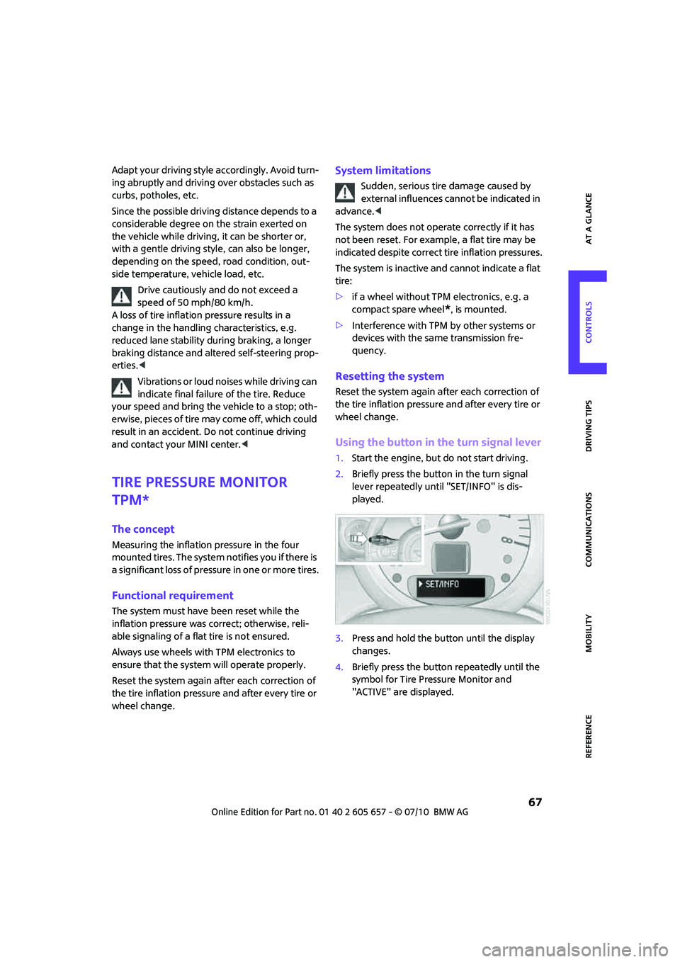
Using the button in the turn signal lever
1.Start the engine, but do not start driving.
2.Briefly press the button in the turn signal
lever repeatedly until "SET/INFO" is dis-
played.
3.Press and hold the button until the display
changes.
4.Briefly press the button repeatedly until the
symbol for Tire Pressure Monitor and
"ACTIVE" are displayed.
Page 71 of 186
69
AT A GLANCE REFERENCE MOBILITYCONTROLS DRIVING TIPS COMMUNICATIONS
Continued driving with a flat tire
When driving with a damaged tire:
1.Avoid sudden braking and steering maneu-
vers.
2.Do not exceed a speed of 50 mph/80 km/h.
3.At the next opportunity, check the air pres-
sure in all four tires.
If the inflation pressure is correct in all four
tires, then the Tire Pressure Monitor may not
have been reset. The system must then be
reset.
Possible driving distance with complete loss of
tire inflation pressure:
The distance it is possible to drive with a flat tire
depends on the load and the stress on the vehi-
cle while driving.
With an average load, it may be possible to drive
for approx. 50 miles/80 km.
When driving with damaged tires, the handling
characteristics change, e.g. the vehicle will skid
sooner when braking, braking distances will be
longer, or self-steering response will change.
Adapt your driving style accordingly. Avoid turn-
ing abruptly and driving over obstacles such as
curbs, potholes, etc.
Since the possible driving distance depends to a
considerable degree on the strain exerted on
the vehicle while driving, it can be shorter or,
with a gentle driving style, can also be longer,
depending on the speed, road condition, out-
side temperature, vehicle load, etc.
Drive cautiously and do not exceed a
speed of 50 mph/80 km/h.
A loss of tire inflation pressure results in a
change in the handling characteristics, e.g.
reduced lane stability during braking, a longer
braking distance and altered self-steering prop-
erties.<
Vibrations or loud noises while driving can
indicate complete failure of the tire.
Reduce your speed and bring the vehicle to a
stop; otherwise, pieces of tire may come off,
which could result in an accident. Do not con-
tinue driving and contact your MINI center.<
Malfunction
The small warning lamp flashes in yel-
low and then lights up continuously; the
larger warning lamp comes on in yel-
low. No punctures can be detected.
This type of message is shown in the following
situations:
>If there is a malfunction.
Have the system checked.
>If a wheel without TPM electronics has been
mounted.
>If TPM is temporarily malfunctioning due to
other systems or devices using the same
radio frequency.
Message for unsuccessful system reset
Both warning lamps come on in yellow.
The system is not reset after a tire has
been changed, for example.
Check the tire inflation pressure and
reset the system, page67.
Declaration according to NHTSA/
FMVSS 138 Tire Pressure Monitoring
Systems
Each tire, including the spare, should be
checked monthly when cold and inflated to the
inflation pressure recommended by the vehicle
manufacturer on the vehicle placard or tire infla-
tion pressure label. If your vehicle has tires of a
different size than the size indicated on the vehi-
cle placard or tire inflation pressure label, you
should determine the proper tire inflation pres-
sure for those tires. As an added safety feature,
your vehicle has been equipped with a tire pres-
sure monitoring system TPMS that illuminates a
low tire pressure telltale when one or more of
your tires are significantly underinflated.
Accordingly, when the low tire pressure telltale
illuminates, you should stop and check your tires
as soon as possible, and inflate them to the
proper pressure. Driving on a significantly
underinflated tire causes the tire to overheat
and can lead to tire failure. Underinflation also
reduces fuel efficiency and tire tread life, and
may affect the vehicle's handling and stopping
ability. Please note that the TPMS is not a substi-
Page 120 of 186
Wheels and tires
118
Wheels and tires
Tire inflation pressures
Information for your safety
It is not merely the tires' service life, but also
driving comfort and, to a great extent, driving
safety that depend on the condition of the tires
and the maintenance of the specified tire pres-
sure.
Checking pressure
Check the tire inflation pressure regularly
and correct it, if necessary: at least twice a
month and before starting long trips. If you fail
to observe this precaution you may be driving
on tires with incorrect tire pressures, a condition
that can not only compromise your vehicle's
driving stability, but also lead to tire damage and
the risk of an accident. Do not drive with
deflated, i.e. flat tires, except when using run-
flat tires. A flat tire will seriously impair your
vehicle's handling and braking response.
Attempts to drive on a flat tire can lead to loss of
control over the vehicle.<
Check the tire inflation pressures only on cold
tires. This means after a maximum of 1.25 miles/
2 km driving or when the vehicle has been
parked for at least 2 hours. When tires are warm,
the tire inflation pressure is higher.
After adjusting the tire inflation pressure,
reinitialize the flat tire monitor, page65,
or reset the Tire Pressure Monitor, page67.<
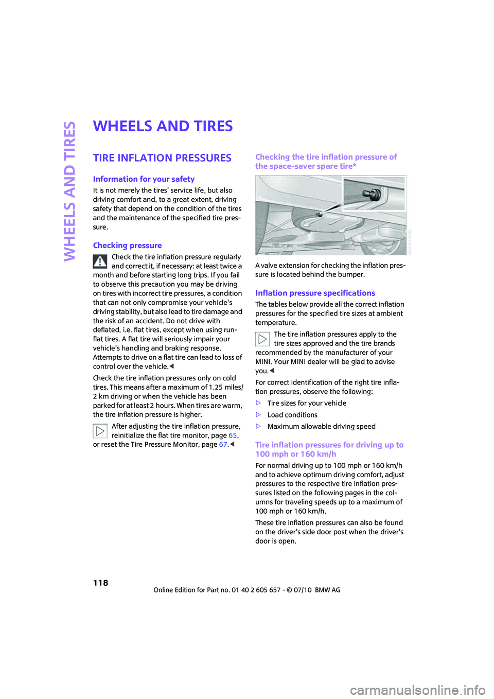
Checking the tire inflation pressure of
the space-saver spare tire*
A valve extension for checking the inflation pres-
sure is located behind the bumper.
Inflation pressure specifications
The tables below provide all the correct inflation
pressures for the specified tire sizes at ambient
temperature.
The tire inflation pressures apply to the
tire sizes approved and the tire brands
recommended by the manufacturer of your
MINI. Your MINI dealer will be glad to advise
you.<
For correct identification of the right tire infla-
tion pressures, observe the following:
>Tire sizes for your vehicle
>Load conditions
>Maximum allowable driving speed
Tire inflation pressures for driving up to
100 mph or 160 km/h
For normal driving up to 100 mph or 160 km/h
and to achieve optimum driving comfort, adjust
pressures to the respective tire inflation pres-
sures listed on the following pages in the col-
umns for traveling speeds up to a maximum of
100 mph or 160 km/h.
These tire inflation pressures can also be found
on the driver's side door post when the driver's
door is open.
Page 128 of 186
Wheels and tires
126
Recommended tire brands
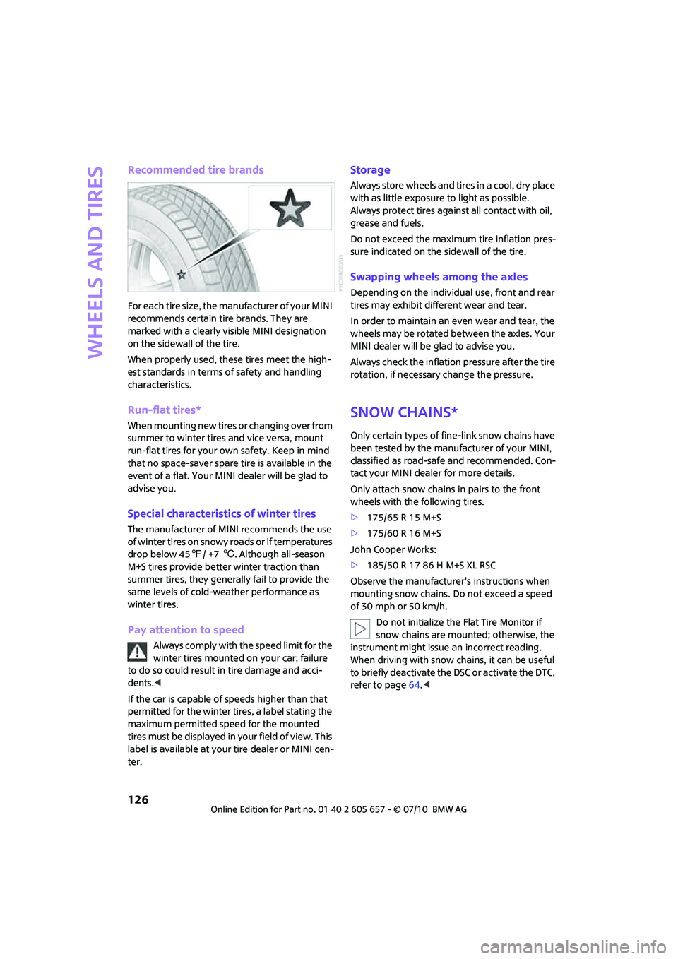
For each tire size, the manufacturer of your MINI
recommends certain tire brands. They are
marked with a clearly visible MINI designation
on the sidewall of the tire.
When properly used, these tires meet the high-
est standards in terms of safety and handling
characteristics.
Run-flat tires*
When mounting new tires or changing over from
summer to winter tires and vice versa, mount
run-flat tires for your own safety. Keep in mind
that no space-saver spare tire is available in the
event of a flat. Your MINI dealer will be glad to
advise you.
Special characteristics of winter tires
The manufacturer of MINI recommends the use
of winter tires on snowy roads or if temperatures
drop below 457/ +76. Although all-season
M+S tires provide better winter traction than
summer tires, they generally fail to provide the
same levels of cold-weather performance as
winter tires.
Pay attention to speed
Always comply with the speed limit for the
winter tires mounted on your car; failure
to do so could result in tire damage and acci-
dents.<
If the car is capable of speeds higher than that
permitted for the winter tires, a label stating the
maximum permitted speed for the mounted
tires must be displayed in your field of view. This
label is available at your tire dealer or MINI cen-
ter.
Storage
Always store wheels and tires in a cool, dry place
with as little exposure to light as possible.
Always protect tires against all contact with oil,
grease and fuels.
Do not exceed the maximum tire inflation pres-
sure indicated on the sidewall of the tire.
Swapping wheels among the axles
Depending on the individual use, front and rear
tires may exhibit different wear and tear.
In order to maintain an even wear and tear, the
wheels may be rotated between the axles. Your
MINI dealer will be glad to advise you.
Always check the inflation pressure after the tire
rotation, if necessary change the pressure.
Snow chains*
Only certain types of fine-link snow chains have
been tested by the manufacturer of your MINI,
classified as road-safe and recommended. Con-
tact your MINI dealer for more details.
Only attach snow chains in pairs to the front
wheels with the following tires.
>175/65 R 15 M+S
>175/60 R 16 M+S
John Cooper Works:
>185/50 R 17 86 H M+S XL RSC
Observe the manufacturer's instructions when
mounting snow chains. Do not exceed a speed
of 30 mph or 50 km/h.
Do not initialize the Flat Tire Monitor if
snow chains are mounted; otherwise, the
instrument might issue an incorrect reading.
When driving with snow chains, it can be useful
to briefly deactivate the DSC or activate the DTC,
refer to page64.<
Page 139 of 186
137
AT A GLANCE REFERENCEMOBILITYCONTROLS DRIVING TIPS COMMUNICATIONS
Replacing components
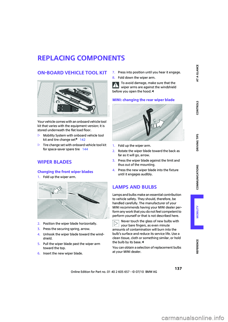
On-board vehicle tool kit
Your vehicle comes with an onboard vehicle tool
kit that varies with the equipment version; it is
stored underneath the flat load floor.
>Mobility System with onboard vehicle tool
kit and tire change set
*142
>Tire change set with onboard vehicle tool kit
for space-saver spare tire144
Wiper blades
Changing the front wiper blades
1.Fold up the wiper arm.
2.Position the wiper blade horizontally.
3.Press the securing spring, arrow.
4.Unhook the wiper blade toward the wind-
shield.
5.Pull the wiper blade past the wiper arm
toward the top.
6.Insert the new wiper blade.7.Press into position until you hear it engage.
8.Fold down the wiper arm.
To avoid damage, make sure that the
wiper arms are against the windshield
before you open the hood.<
MINI: changing the rear wiper blade
1.Fold up the wiper arm.
2.Rotate the wiper blade toward the back as
far as it will go, arrow.
3.Press the wiper blade against the limit and
thus out of the mounting.
4.Press the new wiper blade into the fixture
until it engages audibly.
Lamps and bulbs
Lamps and bulbs make an essential contribution
to vehicle safety. They should, therefore, be
handled carefully. The manufacturer of your
MINI recommends having your MINI dealer per-
f o r m a n y w o r k t h a t y o u d o n o t f e e l c o m p e t e n t t o
perform yourself or that is not described here.
Never touch the glass of new bulbs with
your bare fingers, as even minute
amounts of contamination will burn into the
bulb's surface and reduce its service life. Use a
clean tissue, cloth or something similar, or hold
the bulb by its base.<
You can obtain a selection of replacement bulbs
at your MINI dealer.
Page 144 of 186
Replacing components
142
>MINI Mobility System, refer to the following
section
>Run-flat tires, page125
>Tire change with space-saver spare tire,
page144
MINI Mobility System with onboard
vehicle tool kit and tire change set*
Preparations
Use of the MINI Mobility System may be ineffec-
tive if the tire puncture measures approx. 1/8 in/
4 mm or more. Contact the nearest MINI dealer
if the tire cannot be made drivable with the
Mobility System.
Do not remove foreign bodies which have pen-
etrated the tire if possible.
Follow the instructions on using the Mobil-
ity System found on the compressor and
the sealant bottle.<
Remove the adhesive label for the speed limit
from the sealant bottle and affix it to the steer-
ing wheel.
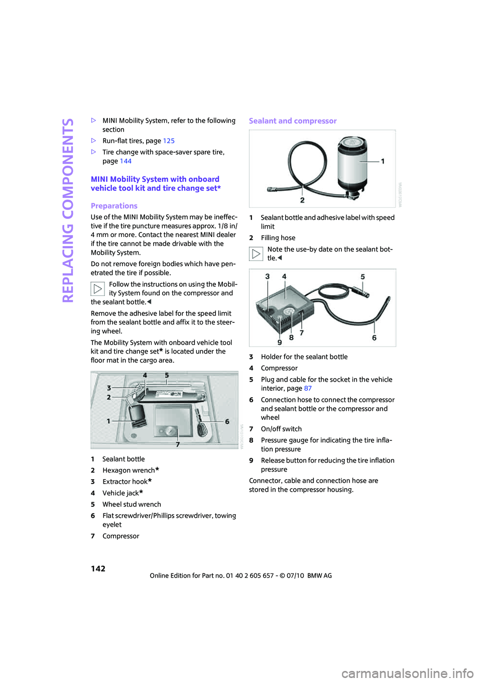
The Mobility System with onboard vehicle tool
kit and tire change set
* is located under the
floor mat in the cargo area.
1Sealant bottle
2Hexagon wrench
*
3Extractor hook*
4Vehicle jack*
5Wheel stud wrench
6Flat screwdriver/Phillips screwdriver, towing
eyelet
7Compressor
Sealant and compressor
1Sealant bottle and adhesive label with speed
limit
2Filling hose
Note the use-by date on the sealant bot-
tle.<
3Holder for the sealant bottle
4Compressor
5Plug and cable for the socket in the vehicle
interior, page87
6Connection hose to connect the compressor
and sealant bottle or the compressor and
wheel
7On/off switch
8Pressure gauge for indicating the tire infla-
tion pressure
9Release button for reducing the tire inflation
pressure
Connector, cable and connection hose are
stored in the compressor housing.
Page 146 of 186
Replacing components
144
3.Insert the plug 3 into the power socket in the
vehicle interior.
4.Correct inflation pressure to 26 psi/180 kPa.
With the engine running:
>To increase the inflation pressure: switch on
the compressor. To check the current infla-
tion pressure, switch off the compressor.
Do not run the compressor for longer
than 10 minutes; otherwise, the
device will overheat and possibly be dam-
aged.<
>To decrease the inflation pressure: press the
release button5.
If the tire cannot maintain the inflation
pressure, drive the vehicle again, refer to
Distributing the sealant. Then repeat steps
1to4.
If an inflation pressure of 26 psi/180 kPa still
cannot be reached, the tire is too heavily dam-
aged. Contact the nearest MINI dealer.<
Driving on
Do not exceed the permitted maximum
speed of 50 mph/80 km/h; doing so may
result in an accident.<
Replace the defective tire as soon as possible
and have the new wheel/tire assembly bal-
anced.
Have the Mobility System refilled.
Changing wheels
Space-saver spare tire*
To change a space-saver spare tire, proceed as
follows:
>Remove the space-saver spare tire,
page144
>Prepare for tire change, page145
>Jack up vehicle, page146
>Mount space-saver spare tire, page146
>Tighten lug bolts, page146
>Drive with space-saver spare tire, page145
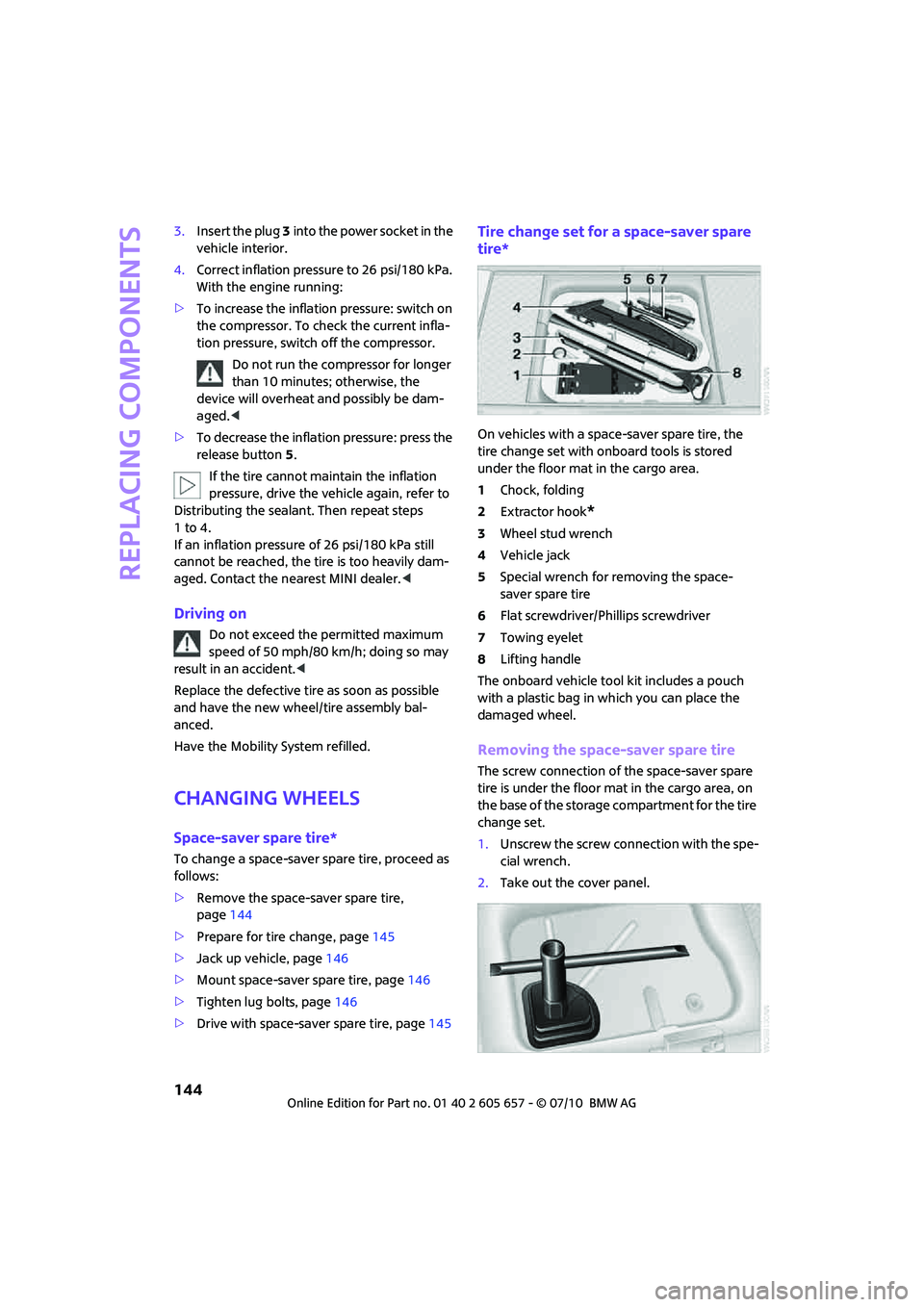
Tire change set for a space-saver spare
tire*
On vehicles with a space-saver spare tire, the
tire change set with onboard tools is stored
under the floor mat in the cargo area.
1Chock, folding
2Extractor hook
*
3Wheel stud wrench
4Vehicle jack
5Special wrench for removing the space-
saver spare tire
6Flat screwdriver/Phillips screwdriver
7Towing eyelet
8Lifting handle
The onboard vehicle tool kit includes a pouch
with a plastic bag in which you can place the
damaged wheel.
Removing the space-saver spare tire
The screw connection of the space-saver spare
tire is under the floor mat in the cargo area, on
the base of the storage compartment for the tire
change set.
1.Unscrew the screw connection with the spe-
cial wrench.
2.Take out the cover panel.
Page 147 of 186
145
AT A GLANCE REFERENCEMOBILITYCONTROLS DRIVING TIPS COMMUNICATIONS
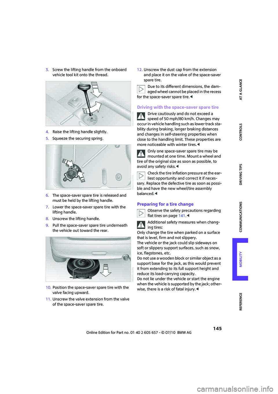
3.Screw the lifting handle from the onboard
vehicle tool kit onto the thread.
4.Raise the lifting handle slightly.
5.Squeeze the securing spring.
6.The space-saver spare tire is released and
must be held by the lifting handle.
7.Lower the space-saver spare tire with the
lifting handle.
8.Unscrew the lifting handle.
9.Pull the space-saver spare tire underneath
the vehicle out toward the rear.
10.Position the space-saver spare tire with the
valve facing upward.
11.Unscrew the valve extension from the valve
of the space-saver spare tire.12.Unscrew the dust cap from the extension
and place it on the valve of the space-saver
spare tire.
Due to its different dimensions, the dam-
aged wheel cannot be placed in the recess
for the space-saver spare tire.<
Driving with the space-saver spare tire
Drive cautiously and do not exceed a
speed of 50 mph/80 km/h. Changes may
occur in vehicle handling such as lower track sta-
bility during braking, longer braking distances
and changes in self-steering properties when
close to the handling limit. These properties are
more noticeable with winter tires.<
Only one space-saver spare tire may be
mounted at one time. Mount a wheel and
tire of the original size as soon as possible, to
avoid any safety risks.<
Check the tire inflation pressure at the ear-
liest opportunity and correct it if neces-
sary. Replace the defective tire as soon as possi-
ble and have the new wheel/tire assembly
balanced.<
Preparing for a tire change
Observe the safety precautions regarding
flat tires on page141.<
Additional safety measures when chang-
ing tires:
Only change the tire when parked on a surface
that is level, firm and not slippery.
The vehicle or the jack could slip sideways on
soft or slippery support surfaces, such as snow,
ice, flagstones, etc.
Do not use a wooden block or similar object as a
support base for the jack, as this would prevent
it from extending to its full support height and
reduce its load-carrying capacity.
Do not lie under the vehicle or start the engine
when the vehicle is supported by the jack; other-
wise, there is a risk of fatal injury.<
Page 148 of 186

Replacing components
146
1.Place the foldable chock* behind the front
wheel on the other side of the vehicle or in
front of the wheel if the vehicle is on an
incline. If the wheel is changed on a surface
with a more severe slope, take additional
precautions to secure the vehicle from roll-
ing.
2.Uncover the lug bolts if necessary.
3.Loosen the lug bolts by a half turn.
Jacking up the vehicle
The vehicle jack is designed for changing
wheels only. Do not attempt to raise
another vehicle model with it or to raise any load
of any kind. To do so could cause accidents and
personal injury.<
1.Place the jack at the jacking point closest to
the wheel.
The jack base must be perpendicular to the
surface beneath the jacking point.
2.During jacking up, insert the jack head in the
square recess of the jacking point.
3.Jack the vehicle up until the wheel you are
changing is raised off the ground.
Mounting the space-saver spare tire
1.Unscrew the lug bolts and remove the
wheel.
2.Remove accumulations of mud or dirt from
the mounting surfaces of the wheel and
hub. Clean the lug bolts.
3.Lift the new wheel into place.
4.Screw at least two lug bolts finger-tight into
opposite bolt holes.
5.Screw in the remaining bolts.
6.Tighten all the lug bolts firmly in a diagonal
pattern.
7.Lower the vehicle.
8.Remove the jack.
Tightening the lug bolts
Tighten the lug bolts in a diagonal pattern.
Immediately have the wheels checked
with a calibrated torque wrench to ensure
that the lug bolts are firmly seated. Otherwise,
incorrectly tightened lug bolts can present a
safety hazard.<
Tightening torque: 103.3 lb ft or 140 Nm.
Replace the defective tire as soon as possible
and have the new wheel/tire assembly bal-
anced.
Vehicle battery
Maintenance
The battery is 100 % maintenance-free, the
electrolyte will last for the life of the battery
when the vehicle is operated in a temperate cli-
mate.
Battery replacement
Only use vehicle batteries that have been
approved for your vehicle by the manu-
facturer; otherwise, the vehicle could be dam-
aged and systems or functions may not be fully
available.<
After a battery replacement, have the battery
registered on the vehicle by your dealer to