start stop button MINI COOPER CONVERTIBLE 2016 User Guide
[x] Cancel search | Manufacturer: MINI, Model Year: 2016, Model line: COOPER CONVERTIBLE, Model: MINI COOPER CONVERTIBLE 2016Pages: 252, PDF Size: 5.41 MB
Page 98 of 252
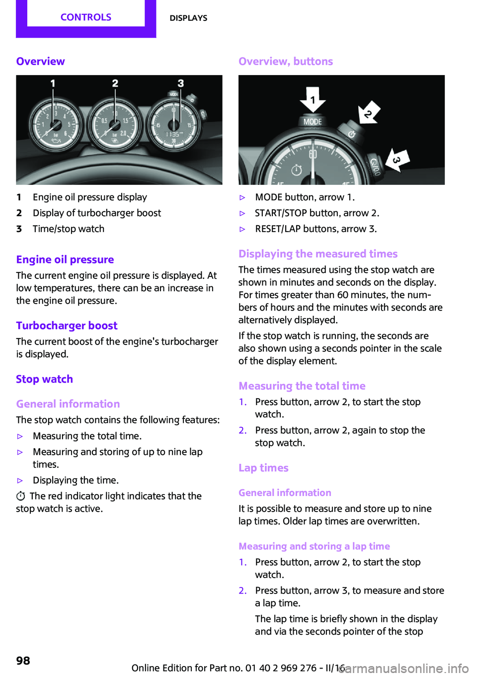
Overview1Engine oil pressure display2Display of turbocharger boost3Time/stop watch
Engine oil pressure
The current engine oil pressure is displayed. At
low temperatures, there can be an increase in
the engine oil pressure.
Turbocharger boostThe current boost of the engine's turbocharger
is displayed.
Stop watch
General information The stop watch contains the following features:
▷Measuring the total time.▷Measuring and storing of up to nine lap
times.▷Displaying the time.
The red indicator light indicates that the
stop watch is active.
Overview, buttons▷MODE button, arrow 1.▷START/STOP button, arrow 2.▷RESET/LAP buttons, arrow 3.
Displaying the measured times
The times measured using the stop watch are
shown in minutes and seconds on the display.
For times greater than 60 minutes, the num‐ bers of hours and the minutes with seconds are
alternatively displayed.
If the stop watch is running, the seconds are
also shown using a seconds pointer in the scale
of the display element.
Measuring the total time
1.Press button, arrow 2, to start the stop
watch.2.Press button, arrow 2, again to stop the
stop watch.
Lap times
General information
It is possible to measure and store up to nine
lap times. Older lap times are overwritten.
Measuring and storing a lap time
1.Press button, arrow 2, to start the stop
watch.2.Press button, arrow 3, to measure and store
a lap time.
The lap time is briefly shown in the display
and via the seconds pointer of the stopSeite 98CONTROLSDisplays98
Online Edition for Part no. 01 40 2 969 276 - II/16
Page 118 of 252
PrewarningThis warning is issued, for example, when there
is the impending danger of a collision or the
distance to the vehicle ahead is too small.
The driver must intervene actively when there is a prewarning.
Acute warning with braking function
Acute warning in displayed in case of the immi‐
nent danger of a collision when the vehicle ap‐
proaches another object at a high differential
speed.
The driver must intervene actively when there
is an acute warning. If necessary, the driver is
assisted by a minor automatic braking inter‐
vention in a possible risk of collision.
Acute warnings can also be triggered without
previous forewarning.
Braking intervention The warning prompts the driver himself/herself
to react. During a warning, the maximum brak‐
ing force is used. Premise for the brake booster
is sufficiently quick and sufficiently hard step‐
ping on the brake pedal. The system can assist
with some braking intervention if there is a risk
of a collision. At low speeds vehicles may thus
come to a complete stop.
Manual transmission: During a braking inter‐
vention up to a complete stop, the engine may
be shut down.
The braking intervention is executed only if ve‐
hicle stability has not been restricted, e.g. by
deactivating the DSC Dynamic Stability Control.
The braking intervention can be interrupted by
stepping on the accelerator pedal or by actively
moving the steering wheel.
Object detection can be restricted. Limitations
of the detection range and functional restric‐
tions are to be considered.System limits
Information WARNING
The system can react incorrectly or not at
all due to the system limits. There is risk of acci‐
dents or risk of property damage. Observe the
information regarding the system limits and ac‐
tively intervene, if needed. ◀
Detection range The system's detection potential is limited.
Thus a system reaction might not come or
might come late.
E. g. the following situations may not be de‐ tected:▷Slow moving vehicles when you approach
them at high speed.▷Vehicles that suddenly swerve in front of
you, or sharply decelerating vehicles.▷Vehicles with an unusual rear appearance.▷Two-wheeled vehicles ahead of you.
Functional limitations
The system may not be fully functional in the
following situations:
▷In heavy fog, rain, sprayed water or snow‐
fall.▷In tight curves.▷If the field of view of the camera or the
windshield are dirty or covered.▷If the driving stability control systems are
deactivated, for example DSC OFF.▷Up to 10 seconds after the start of the en‐
gine, via the Start/Stop button.▷During calibration of the camera immedi‐
ately after vehicle delivery.▷If there are constant blinding effects be‐
cause of oncoming light, e. g., from the sun
low in the sky.Seite 118CONTROLSSafety118
Online Edition for Part no. 01 40 2 969 276 - II/16
Page 121 of 252
System limits
Information WARNING
The system can react incorrectly or not at
all due to the system limits. There is risk of acci‐
dents or risk of property damage. Observe the
information regarding the system limits and ac‐
tively intervene, if needed. ◀
Detection range The detection potential of the camera is lim‐
ited.
Thus a warning might not be issued or be is‐
sued late.
E. g. the following situations may not be de‐
tected:▷Partially covered pedestrians.▷Pedestrians that are not detected as such
because of the viewing angle or contour.▷Pedestrians outside of the detection range.▷Pedestrians having a body size less than
32 inches/80 cm.
Functional limitations
The system may not be fully functional or may
not be available in the following situations:
▷In heavy fog, rain, sprayed water or snow‐
fall.▷In tight curves.▷If the field of view of the camera or the
windshield are dirty or covered.▷If the driving stability control systems are
deactivated, for example DSC OFF.▷Up to 10 seconds after the start of the en‐
gine, via the Start/Stop button.▷During calibration of the camera immedi‐
ately after vehicle delivery.▷If there are constant blinding effects be‐
cause of oncoming light, e. g., from the sun
low in the sky.▷When it is dark outside.
Brake force display
The concept
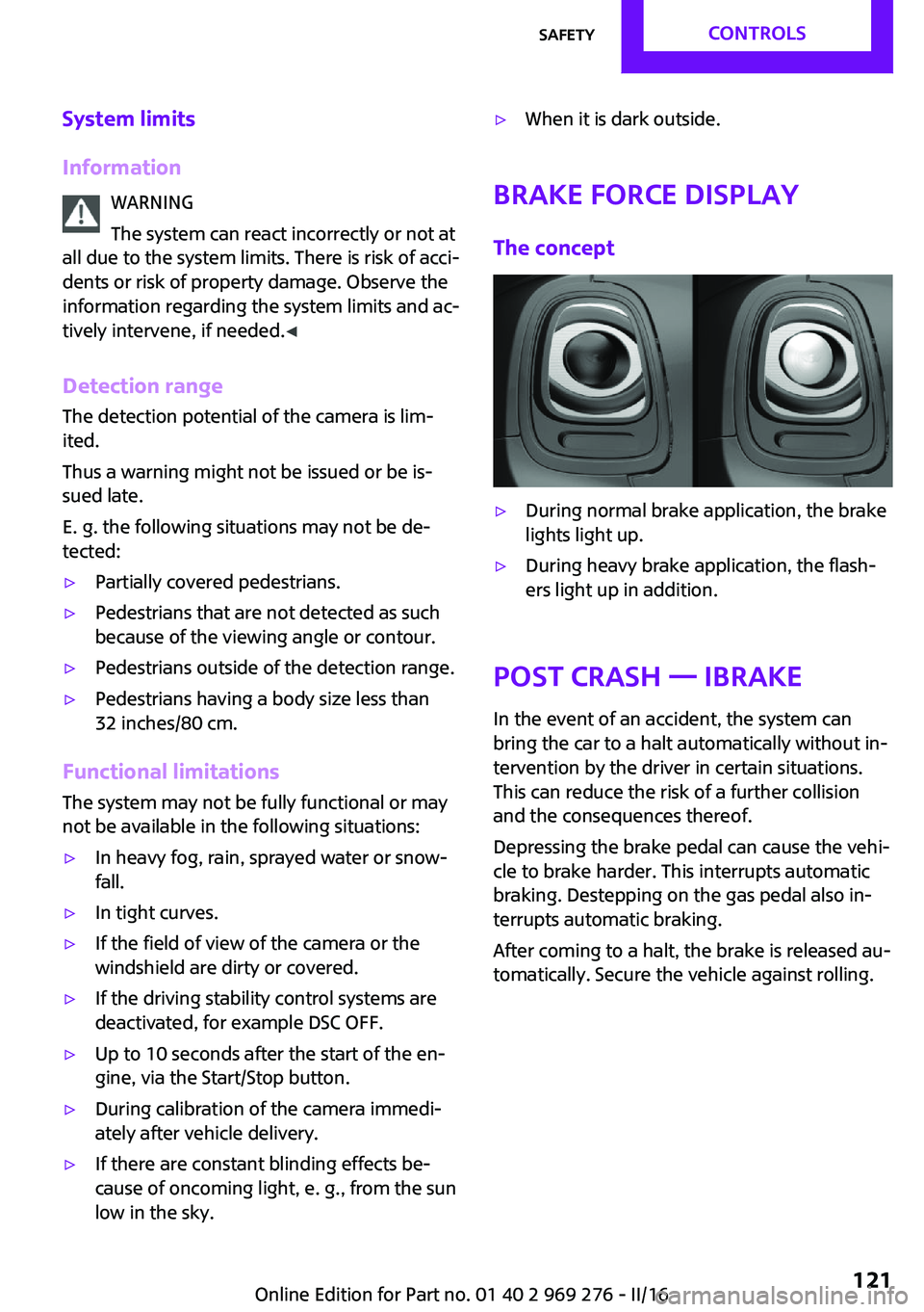
▷During normal brake application, the brake
lights light up.▷During heavy brake application, the flash‐
ers light up in addition.
Post Crash — iBrake
In the event of an accident, the system canbring the car to a halt automatically without in‐
tervention by the driver in certain situations.
This can reduce the risk of a further collision
and the consequences thereof.
Depressing the brake pedal can cause the vehi‐
cle to brake harder. This interrupts automatic
braking. Destepping on the gas pedal also in‐
terrupts automatic braking.
After coming to a halt, the brake is released au‐
tomatically. Secure the vehicle against rolling.
Seite 121SafetyCONTROLS121
Online Edition for Part no. 01 40 2 969 276 - II/16
Page 124 of 252
Dynamic Damping Con‐
trol
The concept
The tuning of the suspension can be changed
with the system.
Programs The system offers several different programs.
Select the programs via the Driving Dynamics
Control, refer to page 124.
MID/GREEN
Balanced tuning of the shock absorbers for
more comfort.
SPORTConsistently sporty tuning of the shock absorb‐
ers for greater driving agility.
Driving Dynamics Con‐
trol
The concept
The Driving Dynamics Control helps to fine-
tune the vehicle's settings and features. Choose
between three different programs. Driving Dy‐
namics Control will activate the particular pro‐
gram.
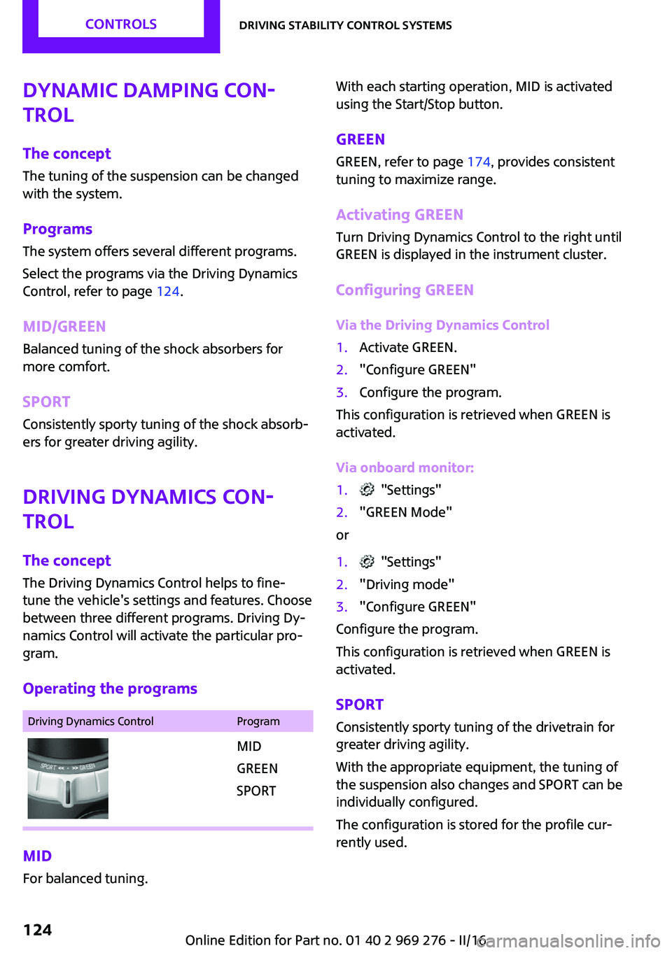
Operating the programsDriving Dynamics ControlProgramMID
GREEN
SPORT
MID For balanced tuning.
With each starting operation, MID is activated
using the Start/Stop button.
GREEN GREEN, refer to page 174, provides consistent
tuning to maximize range.
Activating GREEN
Turn Driving Dynamics Control to the right until
GREEN is displayed in the instrument cluster.
Configuring GREEN
Via the Driving Dynamics Control1.Activate GREEN.2."Configure GREEN"3.Configure the program.
This configuration is retrieved when GREEN is
activated.
Via onboard monitor:
1. "Settings"2."GREEN Mode"
or
1. "Settings"2."Driving mode"3."Configure GREEN"
Configure the program.
This configuration is retrieved when GREEN is
activated.
SPORT
Consistently sporty tuning of the drivetrain for
greater driving agility.
With the appropriate equipment, the tuning of
the suspension also changes and SPORT can be
individually configured.
The configuration is stored for the profile cur‐
rently used.
Seite 124CONTROLSDriving stability control systems124
Online Edition for Part no. 01 40 2 969 276 - II/16
Page 131 of 252
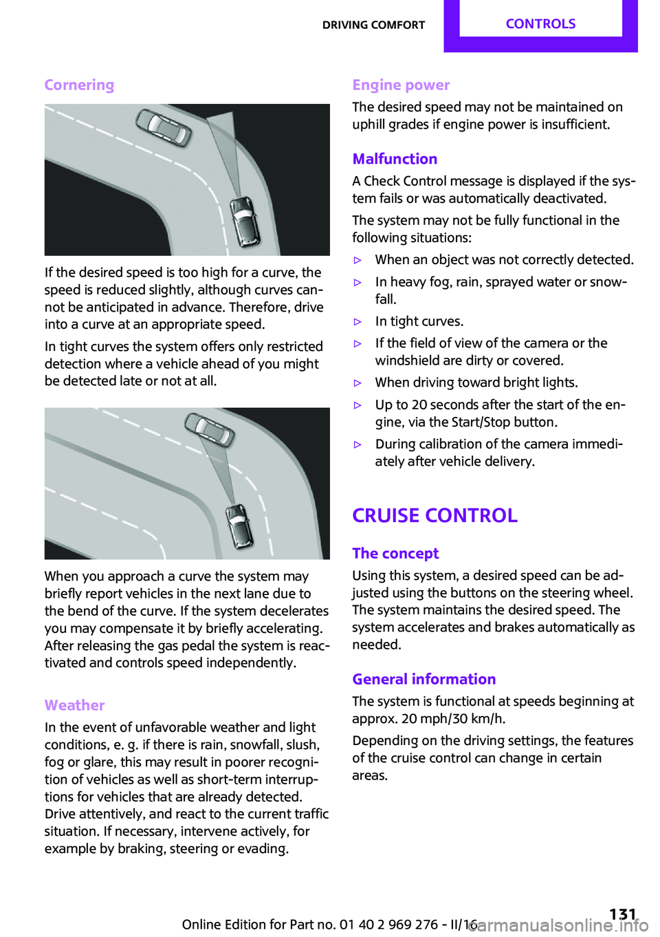
Cornering
If the desired speed is too high for a curve, the
speed is reduced slightly, although curves can‐
not be anticipated in advance. Therefore, drive
into a curve at an appropriate speed.
In tight curves the system offers only restricted
detection where a vehicle ahead of you might
be detected late or not at all.
When you approach a curve the system may
briefly report vehicles in the next lane due to
the bend of the curve. If the system decelerates
you may compensate it by briefly accelerating.
After releasing the gas pedal the system is reac‐
tivated and controls speed independently.
Weather
In the event of unfavorable weather and light conditions, e. g. if there is rain, snowfall, slush,
fog or glare, this may result in poorer recogni‐
tion of vehicles as well as short-term interrup‐
tions for vehicles that are already detected.
Drive attentively, and react to the current traffic
situation. If necessary, intervene actively, for
example by braking, steering or evading.
Engine power
The desired speed may not be maintained on
uphill grades if engine power is insufficient.
Malfunction A Check Control message is displayed if the sys‐
tem fails or was automatically deactivated.
The system may not be fully functional in the
following situations:▷When an object was not correctly detected.▷In heavy fog, rain, sprayed water or snow‐
fall.▷In tight curves.▷If the field of view of the camera or the
windshield are dirty or covered.▷When driving toward bright lights.▷Up to 20 seconds after the start of the en‐
gine, via the Start/Stop button.▷During calibration of the camera immedi‐
ately after vehicle delivery.
Cruise control
The concept
Using this system, a desired speed can be ad‐
justed using the buttons on the steering wheel.
The system maintains the desired speed. The
system accelerates and brakes automatically as
needed.
General information
The system is functional at speeds beginning at
approx. 20 mph/30 km/h.
Depending on the driving settings, the features
of the cruise control can change in certain
areas.
Seite 131Driving comfortCONTROLS131
Online Edition for Part no. 01 40 2 969 276 - II/16
Page 140 of 252
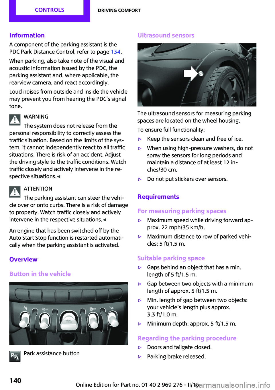
InformationA component of the parking assistant is the
PDC Park Distance Control, refer to page 134.
When parking, also take note of the visual and
acoustic information issued by the PDC, the
parking assistant and, where applicable, the
rearview camera, and react accordingly.
Loud noises from outside and inside the vehicle
may prevent you from hearing the PDC's signal tone.
WARNING
The system does not release from the
personal responsibility to correctly assess the
traffic situation. Based on the limits of the sys‐
tem, it cannot independently react to all traffic situations. There is risk of an accident. Adjust
the driving style to the traffic conditions. Watch
traffic closely and actively intervene in the re‐
spective situations. ◀
ATTENTION
The parking assistant can steer the vehi‐
cle over or onto curbs. There is a risk of damage
to property. Watch traffic closely and actively intervene in the respective situations. ◀
An engine that has been switched off by the
Auto Start Stop function is restarted automati‐
cally when the parking assistant is activated.
Overview
Button in the vehicle
Park assistance button
Ultrasound sensors
The ultrasound sensors for measuring parking
spaces are located on the wheel housing.
To ensure full functionality:
▷Keep the sensors clean and free of ice.▷When using high-pressure washers, do not
spray the sensors for long periods and
maintain a distance of at least 12 in‐
ches/30 cm.▷Do not put stickers over sensors.
Requirements
For measuring parking spaces
▷Maximum speed while driving forward ap‐
prox. 22 mph/35 km/h.▷Maximum distance to row of parked vehi‐
cles: 5 ft/1.5 m.
Suitable parking space
▷Gaps behind an object that has a min.
length of 5 ft/1.5 m.▷Gap between two objects with a minimum
length of approx. 5 ft/1.5 m.▷Min. length of gap between two objects:
your vehicle's length plus approx.
3.3 ft/1.0 m.▷Minimum depth: approx. 5 ft/1.5 m.
Regarding the parking procedure
▷Doors and tailgate closed.▷Parking brake released.Seite 140CONTROLSDriving comfort140
Online Edition for Part no. 01 40 2 969 276 - II/16
Page 184 of 252
FuelVehicle features and op‐
tions
This chapter describes all standard, country-
specific and optional features offered with the
series. It also describes features that are not
necessarily available in your car, e. g., due to
the selected options or country versions. This
also applies to safety-related functions and sys‐
tems. The respectively applicable country provi‐
sions must be observed when using the respec‐
tive features and systems.
Fuel recommendation General information Depending on the region, many gas stations
sell fuel that has been customized to winter or
summer conditions. Fuel that is available in
winter helps make a cold start easier, for exam‐
ple.
Information ATTENTION
Even fuels that conform to the specifica‐
tions can be of low quality. This may cause en‐
gine problems, e.g., poor engine start-up be‐
havior, poor handling and/or poor
performance. There is a risk of damage to
property. In case of engine problems, switch
gas stations or use a brand name fuel with a
higher octane rating. ◀
Gasoline
General information For the best fuel efficiency, the gasoline should
be sulfur-free or very low in sulfur content.Fuels that are marked on the gas pump as con‐
taining metal must not be used.
Fuels with a maximum ethanol content of
25 %, i. e. E10 or E25, may be used for refuel‐
ing.
Ethanol should meet the following quality
standards:
US: ASTM 4806–xx
CAN: CGSB-3.511–xx
xx: comply with the current standard in each
case.
Information ATTENTION
Do not press the Start/Stop button after
refueling with the wrong fuel. Furthermore, the
catalytic converter is permanently damaged.
There is a risk of damage to property. Do not
refuel or add the following in the case of gaso‐
line engines:▷Leaded gasoline.▷Metallic additives, e.g., manganese or iron.
Do not press the Start/Stop button after refuel‐
ing with the wrong fuel. Contact a dealer’s serv‐
ice center or another qualified service center or
repair shop. ◀
ATTENTION
Incorrect fuels can damage the fuel sys‐
tem and the engine. There is a risk of damage
to property. Do not use a fuel with a higher
ethanol percentage than recommended or one
with other types of alcohol, e.g., M5 to M100. ◀
ATTENTION
Fuel that does not comply with the mini‐
mum quality can compromise engine function
or cause engine damage. There is a risk of
damage to property. Do not fill with fuel that
does not comply with the minimum quality. ◀
Seite 184MOBILITYFuel184
Online Edition for Part no. 01 40 2 969 276 - II/16
Page 227 of 252
Before driving into a car washIn order to ensure that the vehicle can roll in a
car wash, take the following steps:
Manual transmission:1.Drive into the car wash.2.Shift to neutral.3.Switch the engine off.4.Switch on the ignition.
Steptronic transmission:
1.Drive into the car wash.2.Engage selector lever position N.3.Make sure that the parking brake is re‐
leased.4.Press the Start/Stop button to switch off the
engine.
In this way, the ignition remains switched
on, and two Check-Control messages are
displayed.
A signal sounds when you leave the vehicle
while in selector lever position N.
The vehicle cannot be locked from the outside
when in selector lever position N. A signal is
sounded when an attempt is made to lock the
vehicle.
To start the engine with manual transmission:
1.Press on the clutch pedal.2.Press the Start/Stop button.
To start the engine with Steptronic transmis‐
sion:
1.Depress the brake pedal.2.Press the Start/Stop button.
Headlights
▷Do not rub dry and do not use abrasive or
acidic cleansers.▷Soak areas that have been dirtied e. g.,
from insects, with shampoo and wash off
with water.▷Thaw ice with de-icing spray; do not use an
ice scraper.
After washing the vehicle
After washing the vehicle, apply the brakes
briefly to dry them; otherwise, braking action
can be reduced and corrosion of the brake
discs can occur.
Completely remove all residues on the win‐
dows, to minimize loss of visibility due to
smearing and to reduce wiper noises and wiper
blade wear.
Vehicle care Vehicle care products
The manufacturer of your vehicle recommends
using care and cleaning products from MINI.
WARNING
Cleansers can contain substances that are
dangerous and harmful to your health. There is
a risk of injury. When cleaning the interior,
open the doors or windows. Only use products
intended for cleaning vehicles. Follow the in‐
structions on the container. ◀
Vehicle paint Regular care contributes to driving safety and
value retention. Environmental influences in
areas with elevated air pollution or natural con‐
taminants, such as tree resin or pollen can af‐
fect the vehicle's paintwork. Tailor the fre‐
quency and extent of your vehicle care to these
influences.
Aggressive substances such as spilled fuel, oil,
grease or bird droppings, must be removed im‐
mediately to prevent the finish from being al‐
tered or discolored.
Caring for the convertible top
The appearance and life of the convertible top
depend on correct care and operation.
Seite 227CareMOBILITY227
Online Edition for Part no. 01 40 2 969 276 - II/16
Page 243 of 252
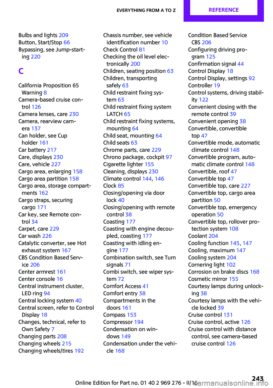
Bulbs and lights 209
Button, Start/Stop 66
Bypassing, see Jump-start‐ ing 220
C California Proposition 65 Warning 8
Camera-based cruise con‐ trol 126
Camera lenses, care 230
Camera, rearview cam‐ era 137
Can holder, see Cup holder 161
Car battery 217
Care, displays 230
Care, vehicle 227
Cargo area, enlarging 158
Cargo area partition 158
Cargo area, storage compart‐ ments 162
Cargo straps, securing cargo 171
Car key, see Remote con‐ trol 34
Carpet, care 229
Car wash 226
Catalytic converter, see Hot exhaust system 167
CBS Condition Based Serv‐ ice 206
Center armrest 161
Center console 16
Central instrument cluster, LED ring 94
Central locking system 40
Central screen, refer to Control Display 18
Changes, technical, refer to Own Safety 7
Changing parts 208
Changing wheels 215
Changing wheels/tires 192 Chassis number, see vehicle
identification number 10
Check Control 81
Checking the oil level elec‐ tronically 200
Children, seating position 63
Children, transporting safely 63
Child restraint fixing sys‐ tem 63
Child restraint fixing system LATCH 65
Child restraint fixing systems, mounting 64
Child seat, mounting 64
Child seats 63
Chrome parts, care 229
Chrono package, cockpit 97
Cigarette lighter 155
Cleaning, displays 230
Climate control 144, 146
Clock 85
Closing/opening via door lock 40
Closing/opening with remote control 38
Coasting 177
Coasting with engine decou‐ pled, coasting 177
Coasting with idling en‐ gine 177
Combination switch, see Turn signals 71
Combi switch, see wiper sys‐ tem 72
Comfort Access 41
Comfort entry 38
Compartments in the doors 161
Compass 153
Compressor 194
Condensation on win‐ dows 149
Condensation under the vehi‐ cle 168 Condition Based Service
CBS 206
Configuring driving pro‐ gram 125
Confirmation signal 44
Control Display 18
Control Display, settings 92
Controller 19
Control systems, driving stabil‐ ity 122
Convenient closing with the remote control 39
Convenient opening 38
Convertible, convertible top 47
Convertible mode, automatic climate control 148
Convertible program, auto‐ matic climate control 148
Convertible, roof 47
Convertible top 47
Convertible top, care 227
Convertible top, cargo area partition 50
Convertible top, emergency operation 50
Convertible top, rollover pro‐ tection system 108
Coolant 204
Cooling function 145, 147
Cooling, maximum 147
Cooling system 204
Cornering light 102
Corrosion on brake discs 168
Cosmetic mirror 155
Courtesy lamps during unlock‐ ing 38
Courtesy lamps with the vehi‐ cle locked 39
Cruise control 131
Cruise control, active 126
Cruise control with distance control, see camera-based
cruise control 126 Seite 243Everything from A to ZREFERENCE243
Online Edition for Part no. 01 40 2 969 276 - II/16
Page 249 of 252
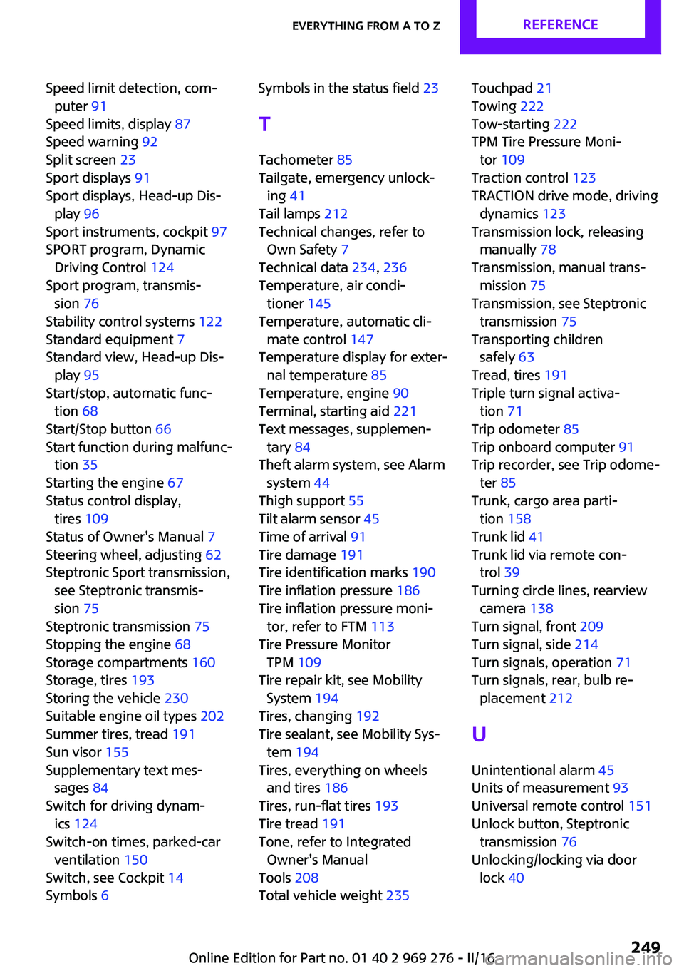
Speed limit detection, com‐puter 91
Speed limits, display 87
Speed warning 92
Split screen 23
Sport displays 91
Sport displays, Head-up Dis‐ play 96
Sport instruments, cockpit 97
SPORT program, Dynamic Driving Control 124
Sport program, transmis‐ sion 76
Stability control systems 122
Standard equipment 7
Standard view, Head-up Dis‐ play 95
Start/stop, automatic func‐ tion 68
Start/Stop button 66
Start function during malfunc‐ tion 35
Starting the engine 67
Status control display, tires 109
Status of Owner's Manual 7
Steering wheel, adjusting 62
Steptronic Sport transmission, see Steptronic transmis‐
sion 75
Steptronic transmission 75
Stopping the engine 68
Storage compartments 160
Storage, tires 193
Storing the vehicle 230
Suitable engine oil types 202
Summer tires, tread 191
Sun visor 155
Supplementary text mes‐ sages 84
Switch for driving dynam‐ ics 124
Switch-on times, parked-car ventilation 150
Switch, see Cockpit 14
Symbols 6 Symbols in the status field 23
T Tachometer 85
Tailgate, emergency unlock‐ ing 41
Tail lamps 212
Technical changes, refer to Own Safety 7
Technical data 234, 236
Temperature, air condi‐ tioner 145
Temperature, automatic cli‐ mate control 147
Temperature display for exter‐ nal temperature 85
Temperature, engine 90
Terminal, starting aid 221
Text messages, supplemen‐ tary 84
Theft alarm system, see Alarm system 44
Thigh support 55
Tilt alarm sensor 45
Time of arrival 91
Tire damage 191
Tire identification marks 190
Tire inflation pressure 186
Tire inflation pressure moni‐ tor, refer to FTM 113
Tire Pressure Monitor TPM 109
Tire repair kit, see Mobility System 194
Tires, changing 192
Tire sealant, see Mobility Sys‐ tem 194
Tires, everything on wheels and tires 186
Tires, run-flat tires 193
Tire tread 191
Tone, refer to Integrated Owner's Manual
Tools 208
Total vehicle weight 235 Touchpad 21
Towing 222
Tow-starting 222
TPM Tire Pressure Moni‐ tor 109
Traction control 123
TRACTION drive mode, driving dynamics 123
Transmission lock, releasing manually 78
Transmission, manual trans‐ mission 75
Transmission, see Steptronic transmission 75
Transporting children safely 63
Tread, tires 191
Triple turn signal activa‐ tion 71
Trip odometer 85
Trip onboard computer 91
Trip recorder, see Trip odome‐ ter 85
Trunk, cargo area parti‐ tion 158
Trunk lid 41
Trunk lid via remote con‐ trol 39
Turning circle lines, rearview camera 138
Turn signal, front 209
Turn signal, side 214
Turn signals, operation 71
Turn signals, rear, bulb re‐ placement 212
U
Unintentional alarm 45
Units of measurement 93
Universal remote control 151
Unlock button, Steptronic transmission 76
Unlocking/locking via door lock 40 Seite 249Everything from A to ZREFERENCE249
Online Edition for Part no. 01 40 2 969 276 - II/16