check engine light MINI Countryman 2011 Owner's Manual (Mini Connected)
[x] Cancel search | Manufacturer: MINI, Model Year: 2011, Model line: Countryman, Model: MINI Countryman 2011Pages: 254, PDF Size: 3.84 MB
Page 15 of 254
CockpitAT A GLANCE
13
Indicator and warning
lamps
The concept
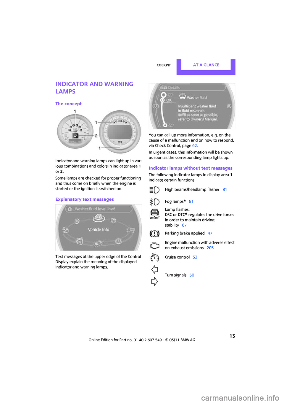
Indicator and warning lamps can light up in var-
ious combinations and colors in indicator area1
or 2.
Some lamps are checked for proper functioning
and thus come on briefly when the engine is
started or the ignition is switched on.
Explanatory text messages
Text messages at the uppe r edge of the Control
Display explain the mean ing of the displayed
indicator and warning lamps. You can call up more information, e.g. on the
cause of a malfunction and on how to respond,
via Check Control, page
62.
In urgent cases, this information will be shown
as soon as the corresponding lamp lights up.
Indicator lamps without text messages
The following indicator lamps in display area 1
indicate certain functions:
High beams/headlamp flasher 81
Fog lamps
*81
Lamp flashes:
DSC or DTC
* regulates the drive forces
in order to maintain driving
stability 67
Parking brake applied 47
Engine malfunction with adverse effect
on exhaust emissions 203
Cruise control 53
Turn signals 50
Page 35 of 254
Opening and closingCONTROLS
33
>Unlocking the liftgate separately
> Starting the engine
Comparison to standard remote controls
Essentially, it makes no difference whether you
control the above-mentioned functions using
Comfort Access or by pressing the buttons on
the remote control for Comfort Access.
Instructions on openin g and closing are found
starting on page 26.
Special features regarding the use of Comfort
Access are described below. If you notice a brief delay while opening or
closing the windows or glass roof, the sys-
tem is checking whether a remote control is
inside the vehicle. Repeat the opening or closing
procedure, if necessary. <
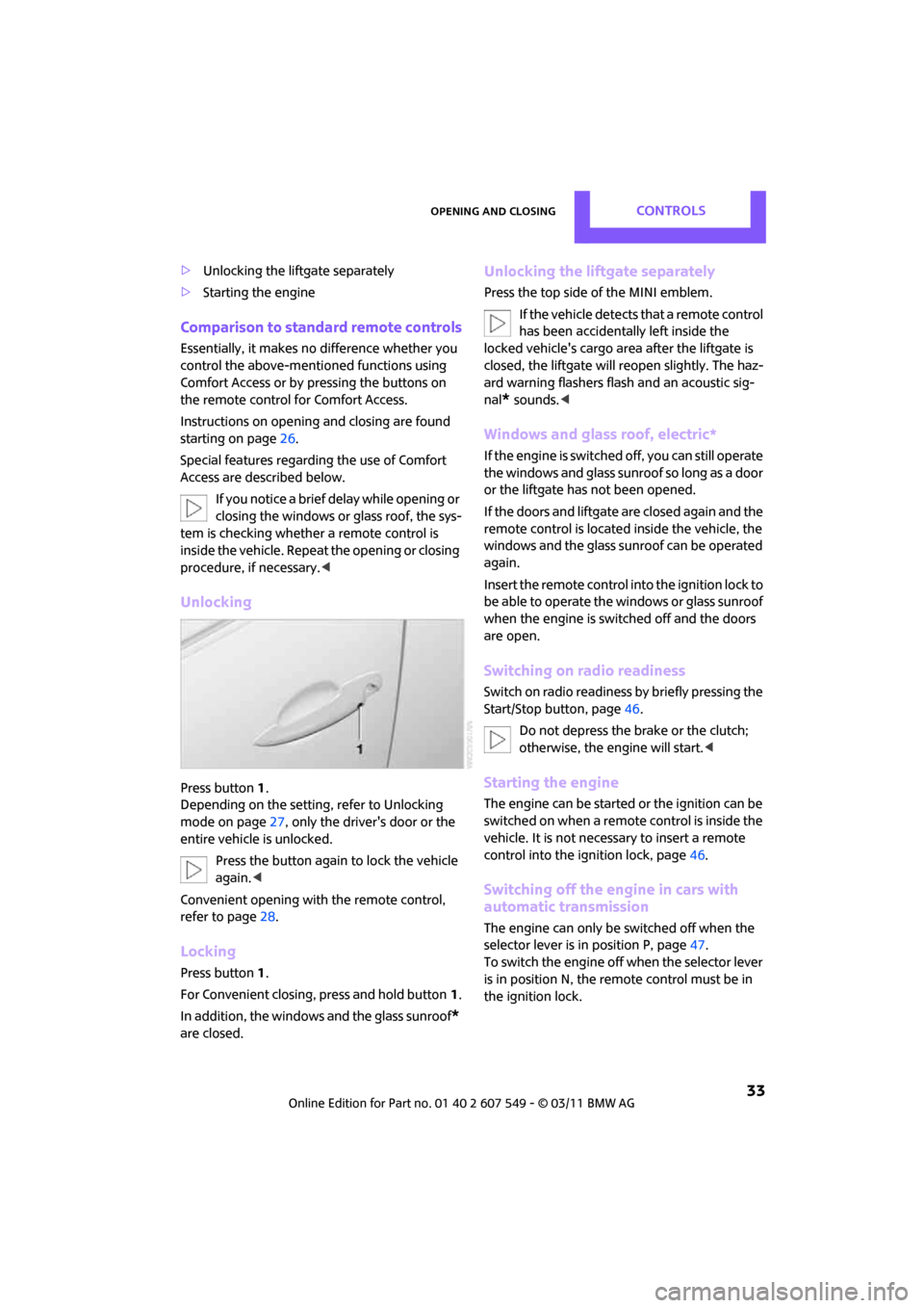
Unlocking
Press button 1.
Depending on the setting, refer to Unlocking
mode on page 27, only the driver's door or the
entire vehicle is unlocked.
Press the button again to lock the vehicle
again. <
Convenient opening with the remote control,
refer to page 28.
Locking
Press button 1.
For Convenient closing, press and hold button 1.
In addition, the windows and the glass sunroof
*
are closed.
Unlocking the liftgate separately
Press the top side of the MINI emblem.
If the vehicle detects that a remote control
has been accidentally left inside the
locked vehicle's cargo area after the liftgate is
closed, the liftgate will reopen slightly. The haz-
ard warning flashers flash and an acoustic sig-
nal
* sounds. <
Windows and glass roof, electric*
If the engine is switched off, you can still operate
the windows and glass sunr oof so long as a door
or the liftgate has not been opened.
If the doors and liftgate are closed again and the
remote control is located inside the vehicle, the
windows and the glass sunroof can be operated
again.
Insert the remote control into the ignition lock to
be able to operate the windows or glass sunroof
when the engine is switched off and the doors
are open.
Switching on radio readiness
Switch on radio readiness by briefly pressing the
Start/Stop button, page 46.
Do not depress the brake or the clutch;
otherwise, the engine will start. <
Starting the engine
The engine can be started or the ignition can be
switched on when a remote control is inside the
vehicle. It is not necessa ry to insert a remote
control into the ignition lock, page 46.
Switching off the engine in cars with
automatic transmission
The engine can only be switched off when the
selector lever is in position P, page47.
To switch the engine off when the selector lever
is in position N, the remote control must be in
the ignition lock.
Page 36 of 254
CONTROLSOpening and closing
34
Before driving a vehicle with automatic
transmission into a car wash
1.Insert remote control into ignition lock.
2. Depress the brake.
3. Move the selector lever to position N.
4. Switch off the engine.
The vehicle can roll.
Malfunction
Comfort Access may malf unction due to local
radio waves.
If this happens, open or close the vehicle via the
buttons on the remote control or using the inte-
grated key.
Insert the remote control into the ignition lock
and start the engine.
Warning lamps
The warning lamp lights up when an
attempt is made to start the engine: the
engine cannot be started. The remote
control is not inside the vehicle or is malfunc-
tioning. Take the remote control with you inside
the vehicle or have it checked. If necessary,
insert another remote co ntrol into the ignition
lock.
The warning lamp lights up when the
engine is running: the remote control is
no longer inside the vehicle. After the
engine is switched off, the engine can only be
restarted within approx. 10 seconds.
The indicator lamp lights up and a mes-
sage appears on the Control Display:
replace the battery in the remote con-
trol.
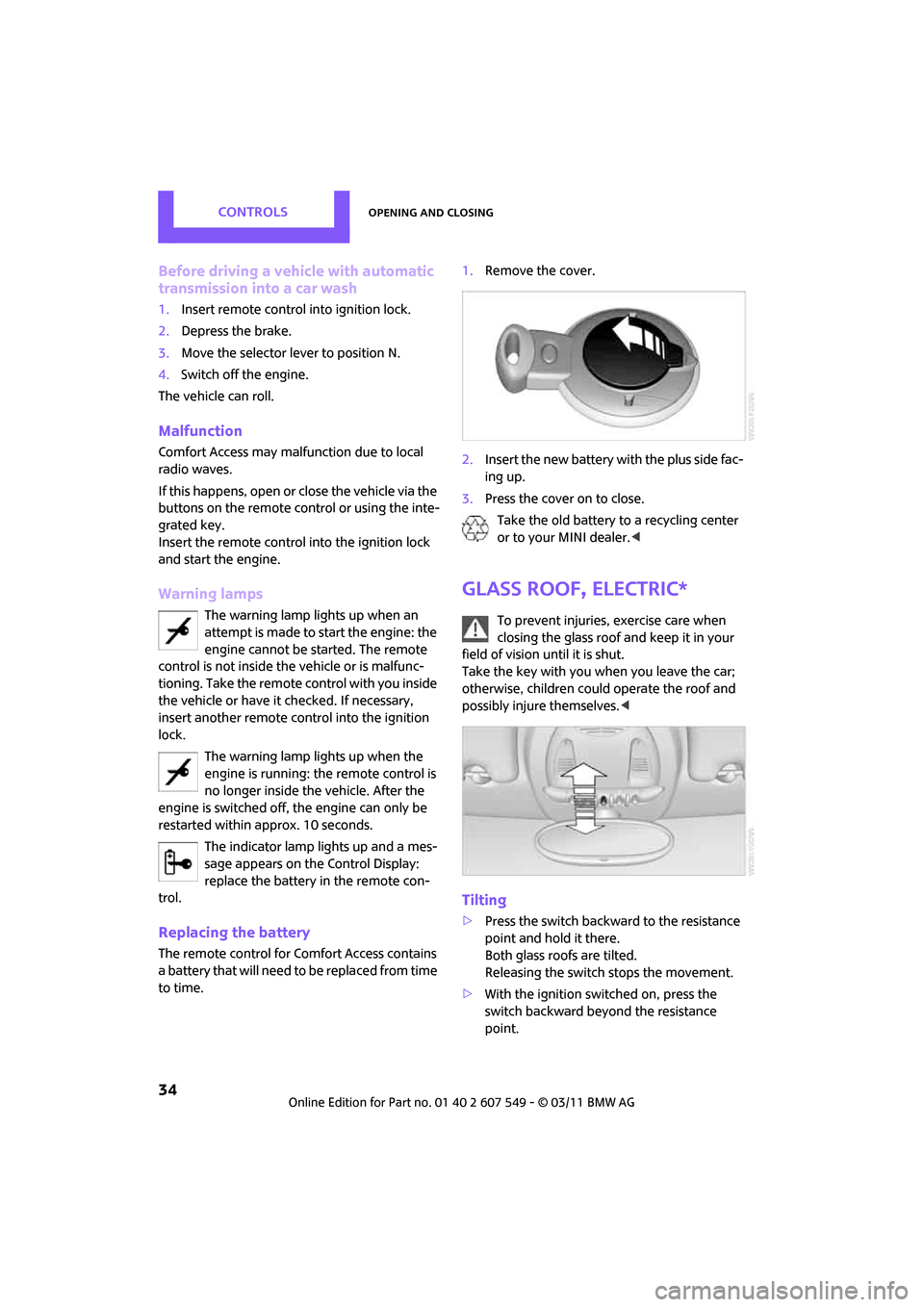
Replacing the battery
The remote control for Comfort Access contains
a b a t t e r y t h a t w i l l n e e d t o b e r e p l a c e d f r o m t i m e
to time. 1.
Remove the cover.
2. Insert the new battery with the plus side fac-
ing up.
3. Press the cover on to close.
Take the old battery to a recycling center
or to your MINI dealer. <
Glass roof, electric*
To prevent injuries, exercise care when
closing the glass roof and keep it in your
field of vision until it is shut.
Take the key with you when you leave the car;
otherwise, children could operate the roof and
possibly injure themselves. <
Tilting
>Press the switch backwa rd to the resistance
point and hold it there.
Both glass roofs are tilted.
Releasing the switch stops the movement.
> With the ignition switched on, press the
switch backward beyond the resistance
point.
Page 68 of 254
CONTROLSTechnology for driving comfort and safety
66
Technology for driving comfort and
safety
Park Distance Control
PDC*
The concept
PDC assists you with parking in reverse. Acoustic
signals and a visual indicator
warn you of the
presence of an object behind the vehicle. The
measurement is carried out by four ultrasonic
sensors in the rear bumper.
These sensors have a range of approx.
6.5ft/2m. However, an acoustic warning
does not sound until an object is approx. 24 in/
60 cm from the rear corner sensors or approx.
5 ft/1.50 m from the rear center sensors. PDC is
a parking aid that can display objects, which are
slowly being approached, which is the usual
case when parking a vehicle. Avoid approaching
an object at high speed; otherwise, physical cir-
cumstances may lead to the system warning
being issued too late. <
Automatic mode
With the engine running or the ignition switched
on, the system is activated automatically after
approx. 1 second when you engage reverse
gear or move the automatic transmission selec-
tor lever to position R. Wait this short period
before driving.
Acoustic signals
As the distance between vehicle and object
decreases, the intervals between the tones
become shorter. If the distance to the nearest
object falls to below roughly 1 ft/30 cm, then a
continuous tone sounds.
If the distance remains co nstant, e.g. when driv-
ing parallel to a wall, th e acoustic signal stops
after approx. 3 seconds.
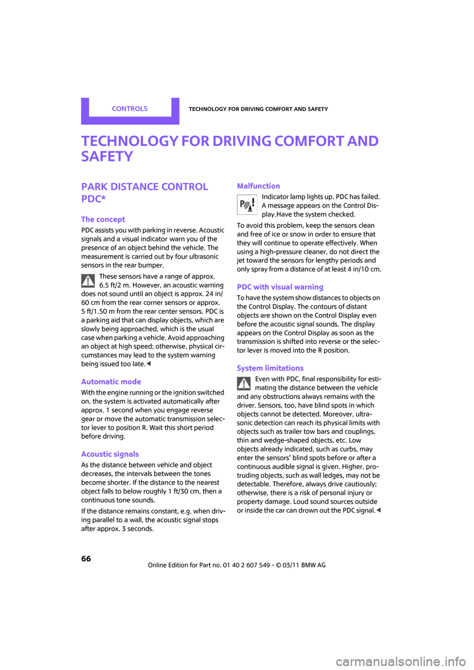
Malfunction
Indicator lamp lights up. PDC has failed.
A message appears on the Control Dis-
play.Have the system checked.
To avoid this problem, keep the sensors clean
and free of ice or snow in order to ensure that
they will continue to operate effectively. When
using a high-pressure cleaner, do not direct the
jet toward the sensors for lengthy periods and
only spray from a distance of at least 4 in/10 cm.
PDC with visual warning
To have the system show distances to objects on
the Control Display. The contours of distant
objects are shown on the Control Display even
before the acoustic sign al sounds. The display
appears on the Control Display as soon as the
transmission is shifted into reverse or the selec-
tor lever is moved into the R position.
System limitations
Even with PDC, final responsibility for esti-
mating the distance between the vehicle
and any obstructions always remains with the
driver. Sensors, too, have blind spots in which
objects cannot be dete cted. Moreover, ultra-
sonic detection can reach its physical limits with
objects such as trailer tow bars and couplings,
thin and wedge-shaped objects, etc. Low
objects already indicated, such as curbs, may
enter the sensors' blind spots before or after a
continuous audible signal is given. Higher, pro-
truding objects, such as wall ledges, may not be
detectable. Therefore, always drive cautiously;
otherwise, there is a risk of personal injury or
property damage. Loud sound sources outside
or inside the car can drown out the PDC signal. <
Page 203 of 254
Under the hoodMOBILITY
201
Coolant temperature
A warning light will come on if the coolant, and
therefore the engine, becomes too hot.
A message appears on the Control Display.
Checking coolant level
Do not add coolant to the cooling system
when the engine is hot. Escaping coolant
can cause burns. <
Do not open the hood until the engine has
cooled down.
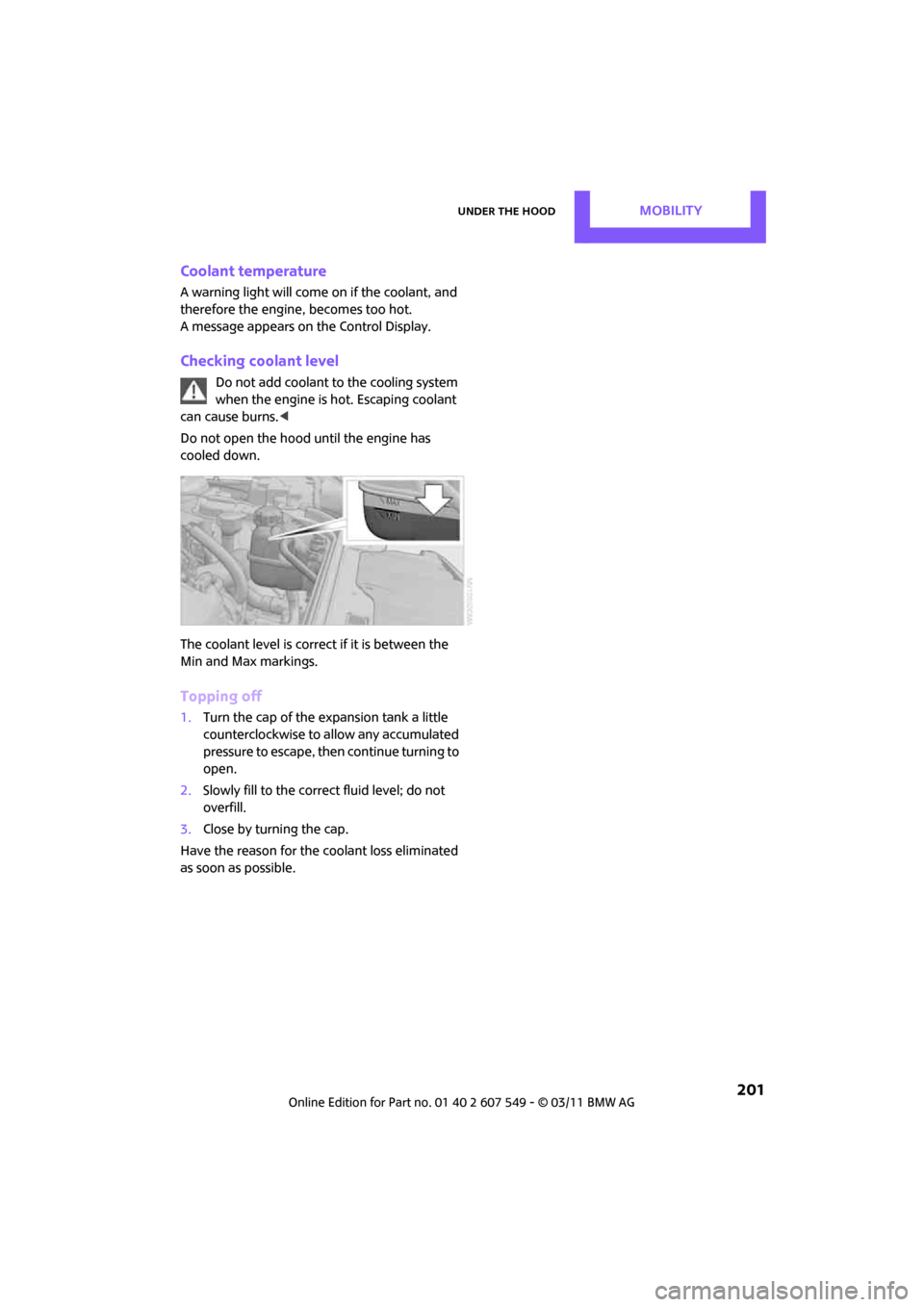
The coolant level is correct if it is between the
Min and Max markings.
Topping off
1. Turn the cap of the expansion tank a little
counterclockwise to allow any accumulated
pressure to escape, then continue turning to
open.
2. Slowly fill to the correct fluid level; do not
overfill.
3. Close by turning the cap.
Have the reason for the coolant loss eliminated
as soon as possible.
Page 205 of 254
MaintenanceMOBILITY
203
Socket for On-Board
Diagnosis OBD
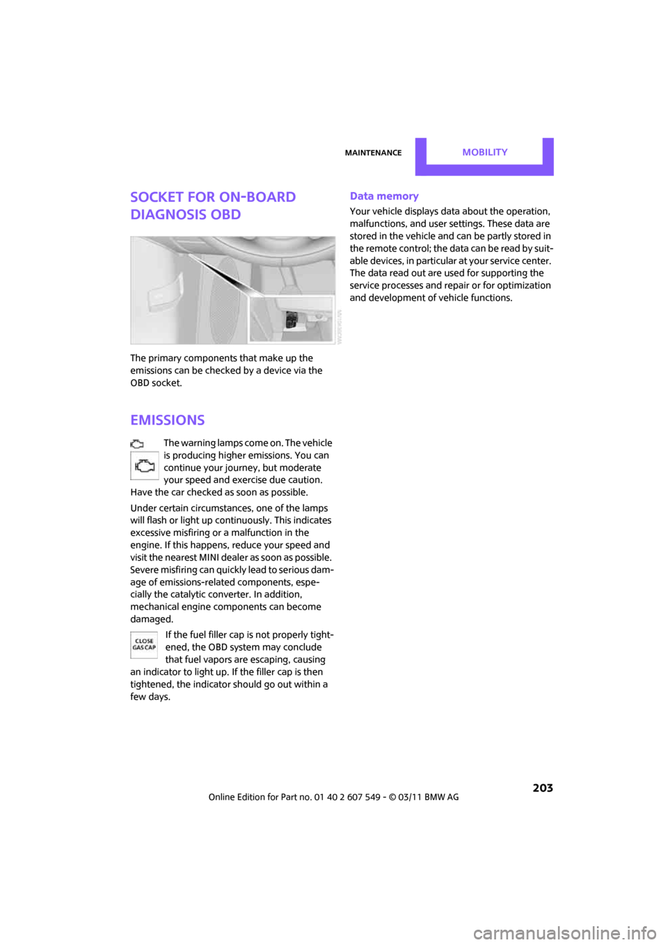
The primary components that make up the
emissions can be checked by a device via the
OBD socket.
Emissions
The warning lamps come on. The vehicle
is producing higher emissions. You can
continue your journey, but moderate
your speed and exercise due caution.
Have the car checked as soon as possible.
Under certain circumstances, one of the lamps
will flash or light up continuously. This indicates
excessive misfiring or a malfunction in the
engine. If this happens, reduce your speed and
visit the nearest MINI dealer as soon as possible.
Severe misfiring can quickly lead to serious dam-
age of emissions-related components, espe-
cially the catalytic converter. In addition,
mechanical engine components can become
damaged.
If the fuel filler cap is not properly tight-
ened, the OBD system may conclude
that fuel vapors are escaping, causing
an indicator to light up. If the filler cap is then
tightened, the indicator should go out within a
few days.
Data memory
Your vehicle displays data about the operation,
malfunctions, and user settings. These data are
stored in the vehicle and can be partly stored in
the remote control; the da ta can be read b y su it-
able devices, in particular at your service center.
The data read out are used for supporting the
service processes and repair or for optimization
and development of vehicle functions.
Page 211 of 254
Replacing componentsMOBILITY
209
tional laser diodes, and legislation defines them
as Class 1 light-emitting diodes.
Do not remove the covers or expose the
eyes directly to the unfiltered light source
for several hours; otherw ise, this could cause
irritation of the retina. <
Headlamp glass lens
In cool or humid weather, condensation may
occur on the interior of outside lights. The con-
densation disappears a short time after the light
is switched on. The headlamps do not need to
be changed. If a lot of moisture is present, e.g.
water droplets in the light, have them checked
by your service center.
Xenon lamps*
The service life of these bulbs is very long and
the probability of failure very low, provided that
they are not switched on and off an excessive
number of times. If a xenon lamp fails neverthe-
less, switch on the fog lamps and continue the
journey with great care, provided that local leg-
islation does not prohibit this.
Have any work on the xenon lamp system,
including bulb replac ement, carried out
only by a MINI dealer or a workshop that has
specially trained personnel working in accor-
dance with the specifications of the MINI manu-
facturer. Due to high voltage, there is a risk of
fatal injury if work on the xenon lamps is carried
out improperly. <
Halogen low beams and high beams
H13 bulb, 60/55 watts
The H13 bulb is pressurized. Therefore,
wear safety glasses an d protective gloves.
Otherwise, there is a risk of injury if the bulb is
damaged. <
Be careful when insta lling the cover; oth-
erwise, leaks could occur and cause dam-
age to the headlamp system. <
Accessing the lamp from the engine
compartment
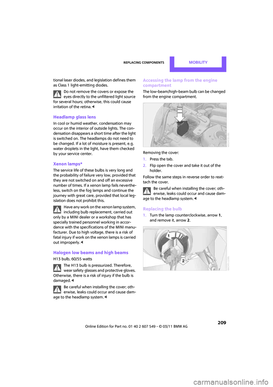
The low-beam/high-beam bulb can be changed
from the engine compartment.
Removing the cover:
1.Press the tab.
2. Flip open the cover and take it out of the
holder.
Follow the same steps in reverse order to reat-
tach the cover. Be careful when insta lling the cover; oth-
erwise, leaks could occur and cause dam-
age to the headlamp system. <
Replacing the bulb
1.Turn the lamp counterclockwise, arrow 1,
and remove it, arrow 2.
Page 221 of 254
Giving and receiving assistanceMOBILITY
219
Connecting jumper cables
Connect the jumper cables in the correct
o r d e r , s o t h a t n o s parks which could cause
injury occur. <
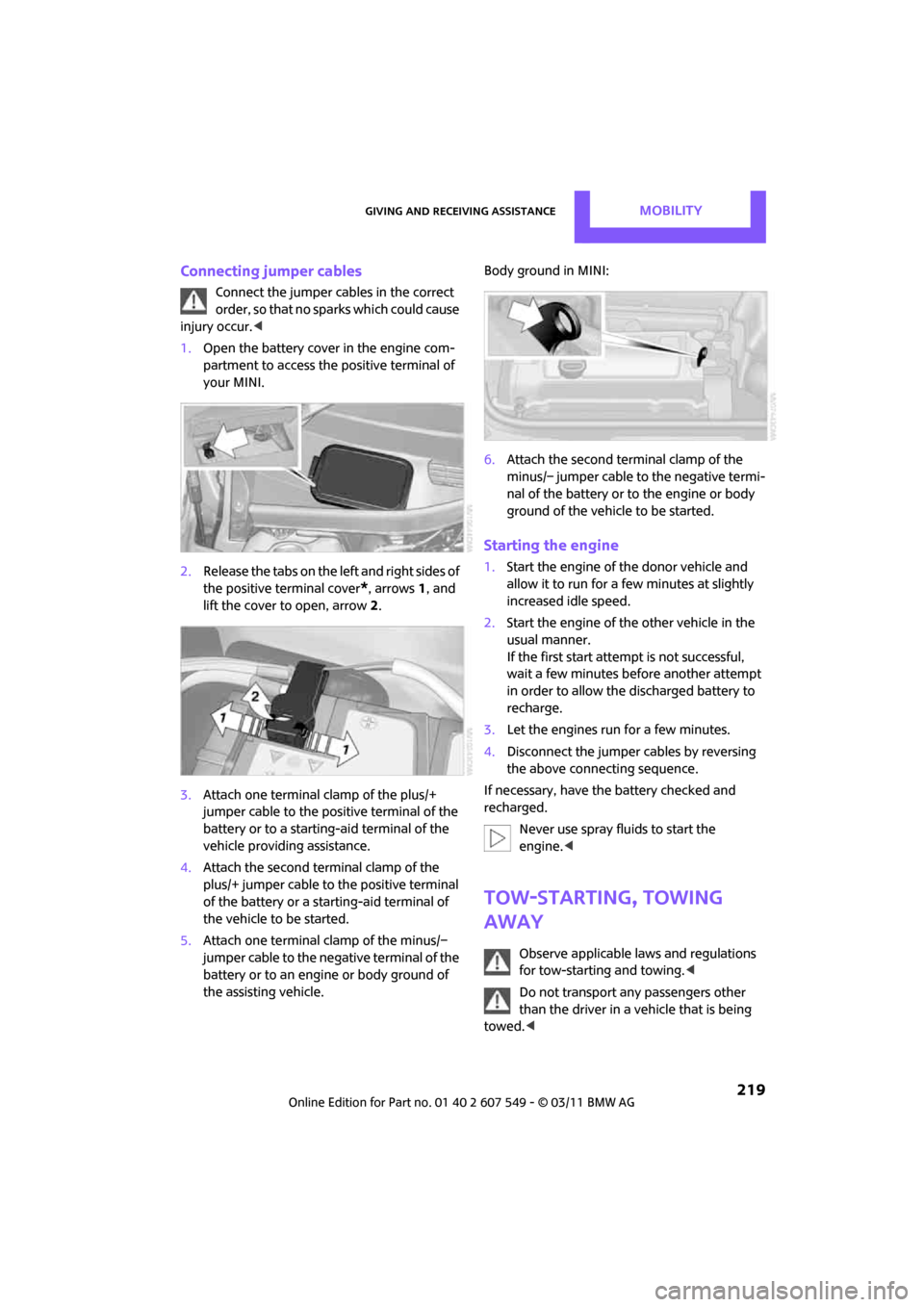
1. Open the battery cover in the engine com-
partment to access the positive terminal of
your MINI.
2. Release the tabs on the left and right sides of
the positive terminal cover
*, arrows 1, and
lift the cover to open, arrow 2.
3. Attach one terminal clamp of the plus/+
jumper cable to the positive terminal of the
battery or to a starting-aid terminal of the
vehicle providing assistance.
4. Attach the second terminal clamp of the
plus/+ jumper cable to the positive terminal
of the battery or a starting-aid terminal of
the vehicle to be started.
5. Attach one terminal clamp of the minus/–
jumper cable to the negative terminal of the
battery or to an engine or body ground of
the assisting vehicle. Body ground in MINI:
6.
Attach the second terminal clamp of the
minus/– jumper cable to the negative termi-
nal of the battery or to the engine or body
ground of the vehicle to be started.
Starting the engine
1.Start the engine of the donor vehicle and
allow it to run for a few minutes at slightly
increased idle speed.
2. Start the engine of the other vehicle in the
usual manner.
If the first start attempt is not successful,
wait a few minutes be fore another attempt
in order to allow the discharged battery to
recharge.
3. Let the engines run for a few minutes.
4. Disconnect the jumper cables by reversing
the above connecting sequence.
If necessary, have the battery checked and
recharged. Never use spray fluids to start the
engine. <
Tow-starting, towing
away
Observe applicable laws and regulations
for tow-starting and towing. <
Do not transport an y passengers other
than the driver in a vehicle that is being
towed. <
Page 238 of 254
236
REFERENCEEverything from A to Z
Everything from A to Z
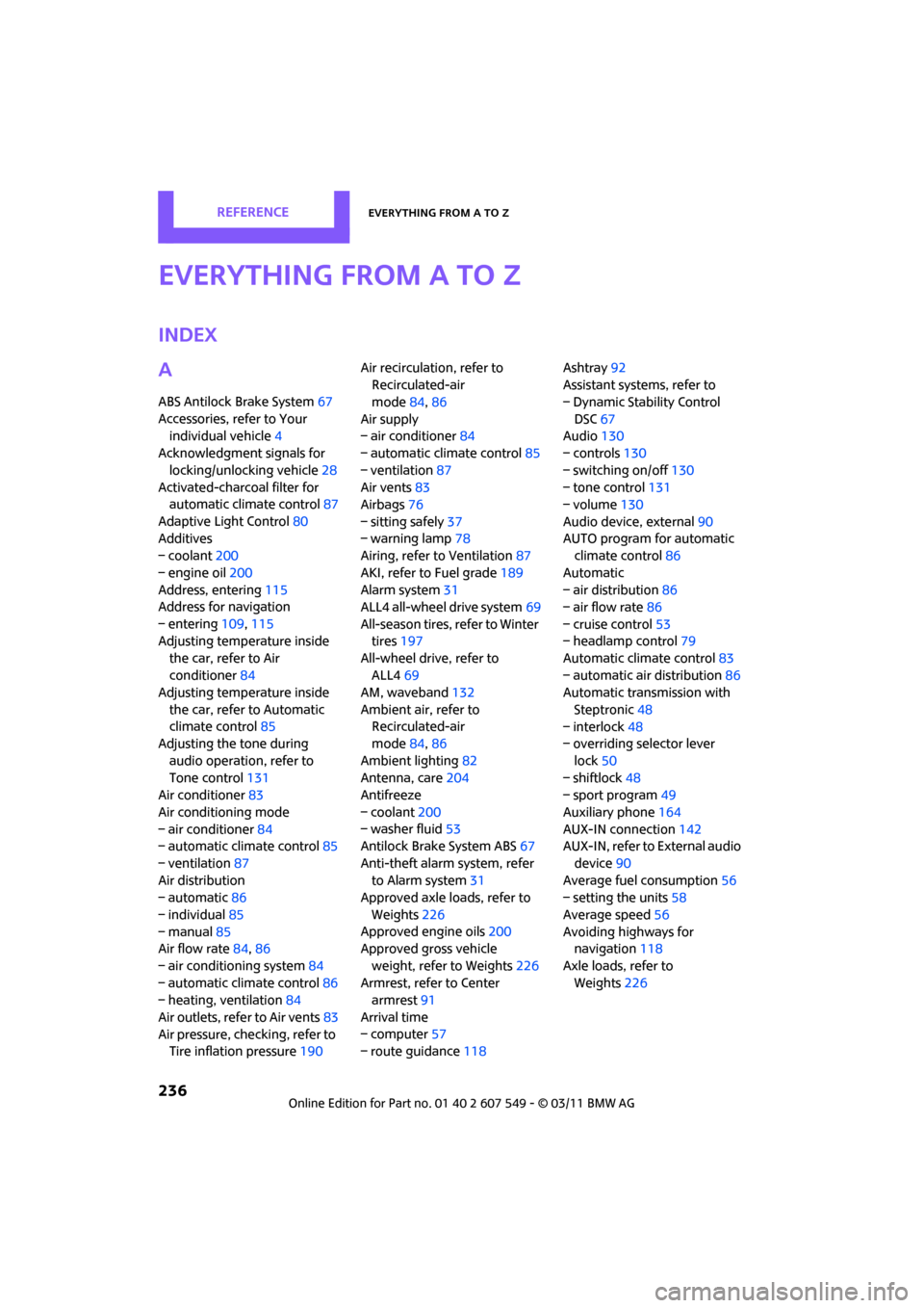
INDEX
A
ABS Antilock Brake System67
Accessories, refer to Your individual vehicle 4
Acknowledgment signals for
locking/unlocking vehicle 28
Activated-charcoa l filter for
automatic climate control 87
Adaptive Light Control 80
Additives
– coolant 200
– engine oil 200
Address, entering 115
Address for navigation
– entering 109,115
Adjusting temperature inside the car, refer to Air
conditioner 84
Adjusting temperature inside
the car, refer to Automatic
climate control 85
Adjusting the tone during
audio operation, refer to
Tone control 131
Air conditioner 83
Air conditioning mode
– air conditioner 84
– automatic cl imate control85
– ventilation 87
Air distribution
– automatic 86
– individual 85
– manual 85
Air flow rate 84,86
– air conditioning system 84
– automatic cl imate control86
– heating, ventilation 84
Air outlets, refer to Air vents 83
Air pressure, checking, refer to Tire inflation pressure 190Air recirculation, refer to
Recirculated-air
mode 84,86
Air supply
– air conditioner 84
– automatic climate control 85
– ventilation 87
Air vents 83
Airbags 76
– sitting safely 37
– warning lamp 78
Airing, refer to Ventilation87
AKI, refer to Fuel grade 189
Alarm system 31
ALL4 all-wheel drive system 69
All-season tires, refer to Winter tires 197
All-wheel drive, refer to
ALL4 69
AM, wa
veband 132
Ambient air, refer to Recirculated-air
mode 84,86
Ambient lighting 82
Antenna, care 204
Antifreeze
– coolant 200
– washer fluid 53
Antilock Brake System ABS 67
Anti-theft alarm system, refer to Alarm system 31
Approved axle loads, refer to
Weights 226
Approved engine oils 200
Approved gross vehicle
weight, refer to Weights 226
Armrest, refer to Center armrest 91
Arrival time
– computer 57
– route guidance 118Ashtray
92
Assistant systems, refer to
– Dynamic Stability Control
DSC 67
Audio 130
– controls 130
– switching on/off 130
– tone control 131
– volume 130
Audio device, external 90
AUTO program for automatic climate control 86
Automatic
– air distribution 86
– air flow rate 86
– cruise control 53
– headlamp control 79
Automatic climate control 83
– automatic air distribution 86
Automatic transmission with
Steptronic 48
– interlock 48
– overriding selector lever
lock 50
– shiftlock 48
– sport program 49
Auxiliary phone 164
AUX-IN connection 142
AUX-IN, refer to External audio
device 90
Average fuel consumption 56
– setting the units 58
Average speed 56
Avoiding highways for navigation 118
Axle loads, refer to Weights 22
6
Page 240 of 254
REFERENCEEverything from A to Z
238
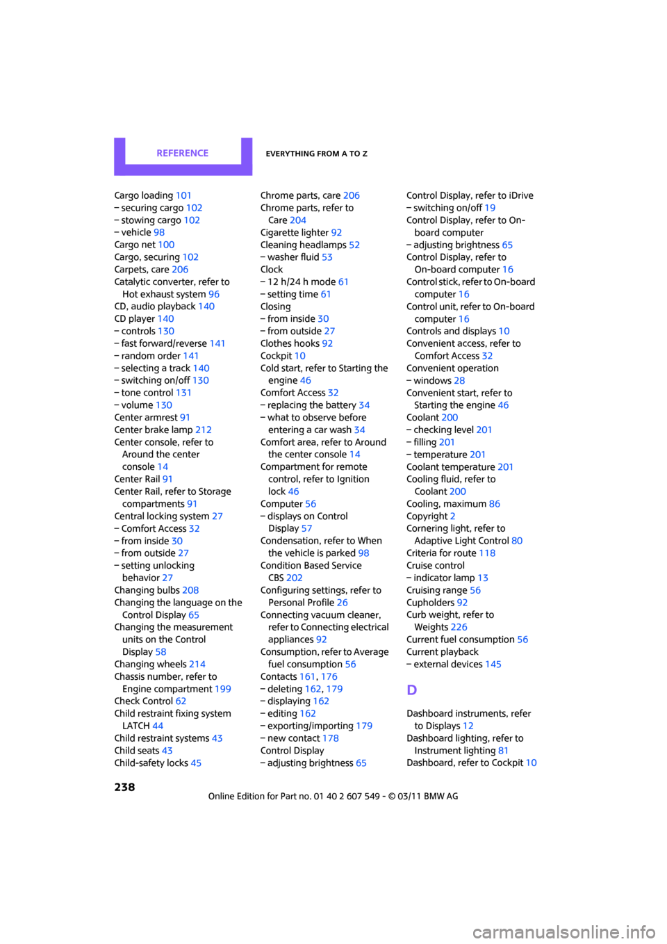
Cargo loading101
– securing cargo 102
– stowing cargo 102
– vehicle 98
Cargo net 100
Cargo, securing 102
Carpets, care 206
Catalytic conver ter, refer to
Hot exhaust system 96
CD, audio playback 140
CD player 140
– controls 130
– fast forward/reverse 141
– random order 141
– selecting a track 140
– switching on/off 130
– tone control 131
– volume 130
Center armrest 91
Center brake lamp 212
Center console, refer to Around the center
console 14
Center Rail 91
Center Rail, refer to Storage
compartments 91
Central locking system 27
– Comfort Access 32
– from inside 30
– from outside 27
– setting unlocking behavior 27
Changing bulbs 208
Changing the language on the Control Display 65
Changing the measurement
units on the Control
Display 58
Changing wheels 214
Chassis number, refer to Engine compartment 199
Check Control 62
Child restraint fixing system LATCH 44
Child restraint systems 43
Child seats 43
Child-safety locks 45Chrome parts, care
206
Chrome parts, refer to Care 204
Cigarette lighter 92
Cleaning headlamps 52
– washer fluid 53
Clock
– 12 h/24 h mode 61
– setting time 61
Closing
– f
rom inside 30
– from outside 27
Clothes hooks 92
Cockpit 10
Cold start, refer to Starting the engine 46
Comfort Access 32
– replacing the battery 34
– what to observe before
entering a car wash 34
Comfort area, refer to Around the center console 14
Compartment for remote control, refer to Ignition
lock 46
Computer 56
– displays on Control Display 57
Condensation, refer to When the vehicle is parked 98
Condition Based Service CBS 202
Configuring settings, refer to
Personal Profile 26
Connecting vacuum cleaner, refer to Connecting electrical
appliances 92
Consumption, refer to Average fuel consumption 56
Contacts 161,176
– deleting 162,179
– displaying 162
– editing 162
– exporting/importing 179
– new contact 178
Control Display
– adjusting brightness 65Control Display, refer to iDrive
– switching on/off
19
Control Display, refer to On- board computer
– adjusting brightness 65
Control Display, refer to On-board computer 16
Control stick, refer to On-board computer 16
Control unit, refer to On-board
computer 16
Controls and displays 10
Convenient access, refer to
Comfort Access 32
Convenient operation
– windows 28
Convenient star t, refer to
Starting the engine 46
Coolant 200
– checking level 201
– filling 201
– temperature 201
Coolant temperature 201
Coo
ling fluid, refer to
Coolant 200
Cooling, maximum 86
Copyright 2
Cornering light, refer to
Adaptive Light Control 80
Criteria for route 118
Cruise control
– indicator lamp 13
Cruising range 56
Cupholders 92
Curb weight, refer to Weights 226
Current fuel consumption 56
Current playback
– external devices 145
D
Dashboard instruments, refer
to Displays 12
Dashboard lighting, refer to
Instrument lighting 81
Dashboard, refer to Cockpit 10