remote start MINI Countryman 2011 Owner's Manual (Mini Connected)
[x] Cancel search | Manufacturer: MINI, Model Year: 2011, Model line: Countryman, Model: MINI Countryman 2011Pages: 254, PDF Size: 3.84 MB
Page 32 of 254
CONTROLSOpening and closing
30
Opening and closing:
from inside
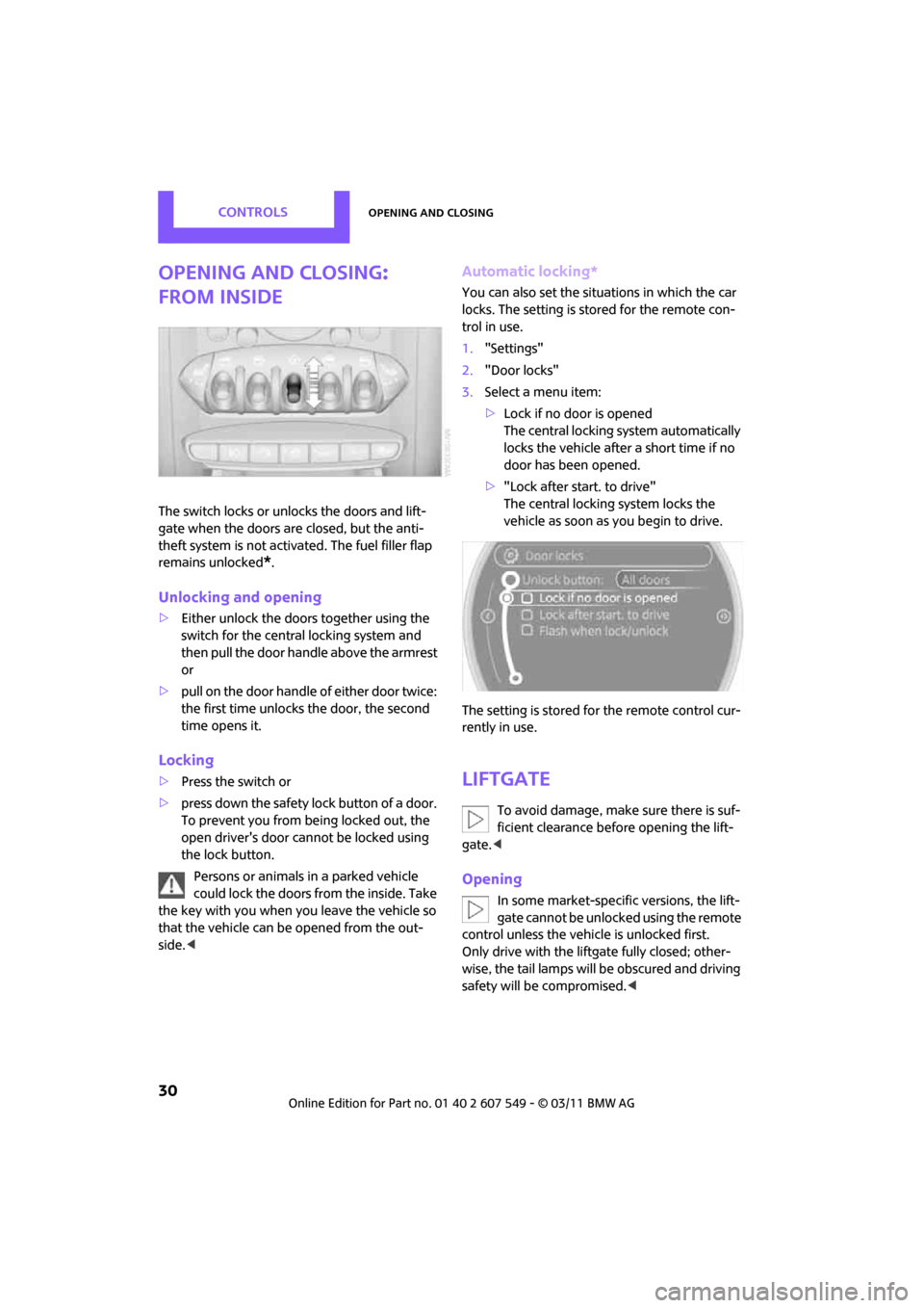
The switch locks or unlocks the doors and lift-
gate when the doors are closed, but the anti-
theft system is not activated. The fuel filler flap
remains unlocked
*.
Unlocking and opening
>Either unlock the doors together using the
switch for the centra l locking system and
then pull the door handle above the armrest
or
> pull on the door handle of either door twice:
the first time unlocks the door, the second
time opens it.
Locking
>Press the switch or
> press down the safety lock button of a door.
To prevent you from being locked out, the
open driver's door cannot be locked using
the lock button.
Persons or animals in a parked vehicle
could lock the doors from the inside. Take
the key with you when you leave the vehicle so
that the vehicle can be opened from the out-
side. <
Automatic locking*
You can also set the situations in which the car
locks. The setting is stored for the remote con-
trol in use.
1."Settings"
2. "Door locks"
3. Select a menu item:
>Lock if no door is opened
The central locking system automatically
locks the vehicle after a short time if no
door has been opened.
> "Lock after start. to drive"
The central locking system locks the
vehicle as soon as you begin to drive.
The setting is stored fo r the remote control cur-
rently in use.
Liftgate
To avoid damage, make sure there is suf-
ficient clearance before opening the lift-
gate. <
Opening
In some market-specific versions, the lift-
gate cannot be unlocked using the remote
control unless the vehicl e is unlocked first.
Only drive with the liftgate fully closed; other-
wise, the tail lamps will be obscured and driving
safety will be compromised. <
Page 34 of 254
CONTROLSOpening and closing
32
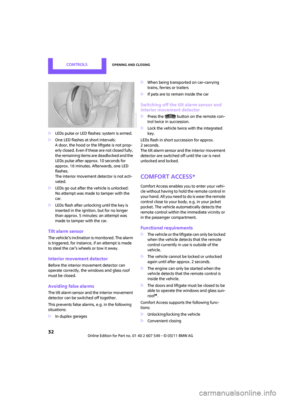
>LEDs pulse or LED flashes: system is armed.
> One LED flashes at short intervals:
A door, the hood or the liftgate is not prop-
erly closed. Even if these are not closed fully,
the remaining items ar e deadlocked and the
LEDs pulse after approx. 10 seconds for
approx. 16 minutes. Afterwards, one LED
flashes.
The interior movement detector is not acti-
vated.
> LEDs go out after the vehicle is unlocked:
No attempt was made to tamper with the
car.
> LEDs flash after unlocking until the key is
inserted in the ignition, but for no longer
than approx. 5 minutes: an attempt was
made to tamper with the car.
Tilt alarm sensor
The vehicle's inclination is monitored. The alarm
is triggered, for instance, if an attempt is made
to steal the car's wheels or tow it away.
Interior movement detector
Before the interior movement detector can
operate correctly, the windows and glass roof
must be closed.
Avoiding false alarms
The tilt alarm sensor and the interior movement
detector can be switched off together.
This prevents false alarms, e.g. in the following
situations:
> In duplex garages >
When being transported on car-carrying
trains, ferries or trailers
> If pets are to remain inside the car
Switching off the tilt alarm sensor and
interior movement detector
>Press the button on the remote con-
trol twice in succession.
> Lock the vehicle twice with the integrated
key.
LEDs flash in short succession for approx.
2seconds.
The tilt alarm sensor and the interior movement
detector are switched off until the car is next
unlocked and locked.
Comfort Access*
Comfort Access enables you to enter your vehi-
cle without having to hold the remote control in
your hand. All you need to do is wear the remote
control close to your body, e.g. in your jacket
pocket. The vehicle automatically detects the
remote control within the immediate vicinity or
in the passenger compartment.
Functional requirements
> The vehicle or the liftgate can only be locked
when the vehicle detects that the remote
control currently in use is outside of the
vehicle.
> The vehicle cannot be locked or unlocked
again until after approx. 2 seconds.
> The engine can only be started when the
vehicle detects that the remote control is
inside the vehicle.
> The doors and liftgate must be closed to be
able to operate the windows and glass sun-
roof
*.
Comfort Access support s the following func-
tions:
> Unlocking/locking the vehicle
> Convenient closing
Page 35 of 254
Opening and closingCONTROLS
33
>Unlocking the liftgate separately
> Starting the engine
Comparison to standard remote controls
Essentially, it makes no difference whether you
control the above-mentioned functions using
Comfort Access or by pressing the buttons on
the remote control for Comfort Access.
Instructions on openin g and closing are found
starting on page 26.
Special features regarding the use of Comfort
Access are described below. If you notice a brief delay while opening or
closing the windows or glass roof, the sys-
tem is checking whether a remote control is
inside the vehicle. Repeat the opening or closing
procedure, if necessary. <
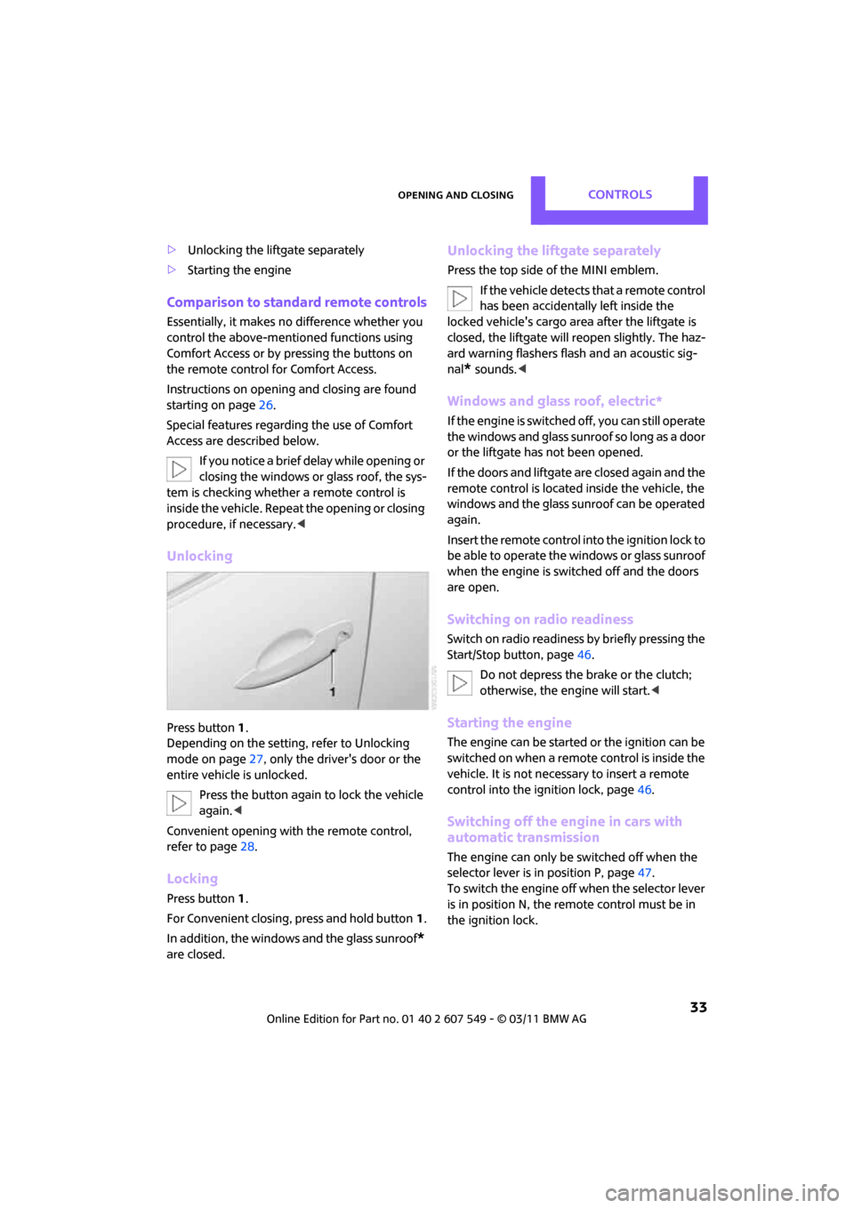
Unlocking
Press button 1.
Depending on the setting, refer to Unlocking
mode on page 27, only the driver's door or the
entire vehicle is unlocked.
Press the button again to lock the vehicle
again. <
Convenient opening with the remote control,
refer to page 28.
Locking
Press button 1.
For Convenient closing, press and hold button 1.
In addition, the windows and the glass sunroof
*
are closed.
Unlocking the liftgate separately
Press the top side of the MINI emblem.
If the vehicle detects that a remote control
has been accidentally left inside the
locked vehicle's cargo area after the liftgate is
closed, the liftgate will reopen slightly. The haz-
ard warning flashers flash and an acoustic sig-
nal
* sounds. <
Windows and glass roof, electric*
If the engine is switched off, you can still operate
the windows and glass sunr oof so long as a door
or the liftgate has not been opened.
If the doors and liftgate are closed again and the
remote control is located inside the vehicle, the
windows and the glass sunroof can be operated
again.
Insert the remote control into the ignition lock to
be able to operate the windows or glass sunroof
when the engine is switched off and the doors
are open.
Switching on radio readiness
Switch on radio readiness by briefly pressing the
Start/Stop button, page 46.
Do not depress the brake or the clutch;
otherwise, the engine will start. <
Starting the engine
The engine can be started or the ignition can be
switched on when a remote control is inside the
vehicle. It is not necessa ry to insert a remote
control into the ignition lock, page 46.
Switching off the engine in cars with
automatic transmission
The engine can only be switched off when the
selector lever is in position P, page47.
To switch the engine off when the selector lever
is in position N, the remote control must be in
the ignition lock.
Page 36 of 254
CONTROLSOpening and closing
34
Before driving a vehicle with automatic
transmission into a car wash
1.Insert remote control into ignition lock.
2. Depress the brake.
3. Move the selector lever to position N.
4. Switch off the engine.
The vehicle can roll.
Malfunction
Comfort Access may malf unction due to local
radio waves.
If this happens, open or close the vehicle via the
buttons on the remote control or using the inte-
grated key.
Insert the remote control into the ignition lock
and start the engine.
Warning lamps
The warning lamp lights up when an
attempt is made to start the engine: the
engine cannot be started. The remote
control is not inside the vehicle or is malfunc-
tioning. Take the remote control with you inside
the vehicle or have it checked. If necessary,
insert another remote co ntrol into the ignition
lock.
The warning lamp lights up when the
engine is running: the remote control is
no longer inside the vehicle. After the
engine is switched off, the engine can only be
restarted within approx. 10 seconds.
The indicator lamp lights up and a mes-
sage appears on the Control Display:
replace the battery in the remote con-
trol.
Replacing the battery
The remote control for Comfort Access contains
a b a t t e r y t h a t w i l l n e e d t o b e r e p l a c e d f r o m t i m e
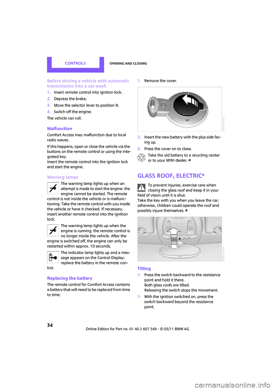
to time. 1.
Remove the cover.
2. Insert the new battery with the plus side fac-
ing up.
3. Press the cover on to close.
Take the old battery to a recycling center
or to your MINI dealer. <
Glass roof, electric*
To prevent injuries, exercise care when
closing the glass roof and keep it in your
field of vision until it is shut.
Take the key with you when you leave the car;
otherwise, children could operate the roof and
possibly injure themselves. <
Tilting
>Press the switch backwa rd to the resistance
point and hold it there.
Both glass roofs are tilted.
Releasing the switch stops the movement.
> With the ignition switched on, press the
switch backward beyond the resistance
point.
Page 48 of 254
CONTROLSDriving
46
Driving
Ignition lock
Inserting the key into the ignition lock
Insert the key all the way into the ignition lock.
Radio readiness
Individual electrical consumers can operate.
Removing the key from the ignition lock
Press in the key briefly. It is ejected slightly.
At the same time:
>The ignition is switched off if it was on
beforehand.
Automatic transmission
The key can only be removed if the selector lever
is in position P: interlock.
Start/Stop button
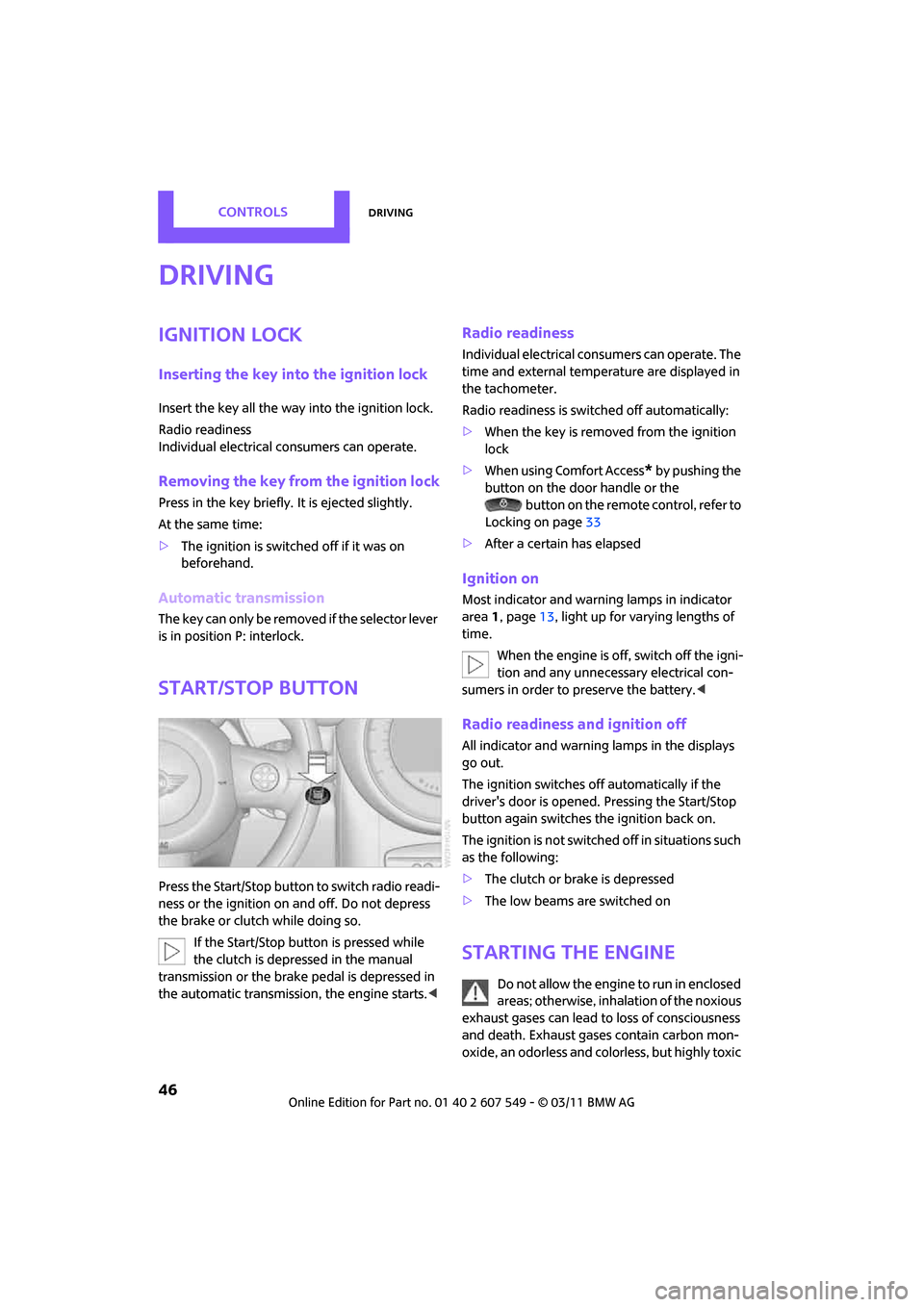
Press the Start/Stop button to switch radio readi-
ness or the ignition on and off. Do not depress
the brake or clutch while doing so.
If the Start/Stop button is pressed while
the clutch is depressed in the manual
transmission or the brake pedal is depressed in
the automatic transmission, the engine starts. <
Radio readiness
Individual electrical consumers can operate. The
time and external temperature are displayed in
the tachometer.
Radio readiness is switched off automatically:
>When the key is removed from the ignition
lock
> When using Comfort Access
* by pushing the
button on the door handle or the button on the remote control, refer to
Locking on page 33
> After a certain has elapsed
Ignition on
Most indicator and warn ing lamps in indicator
area 1, page 13, light up for varying lengths of
time.
When the engine is off, switch off the igni-
tion and any unnecessary electrical con-
sumers in order to preserve the battery. <
Radio readiness and ignition off
All indicator and warning lamps in the displays
go out.
The ignition switches off automatically if the
driver's door is opened. Pressing the Start/Stop
button again switches the ignition back on.
The ignition is not switched off in situations such
as the following:
> The clutch or brake is depressed
> The low beams are switched on
Starting the engine
Do not allow the engine to run in enclosed
areas; otherwise, inhalation of the noxious
exhaust gases can lead to loss of consciousness
and death. Exhaust gases contain carbon mon-
oxide, an odorless and colo rless, but highly toxic
Page 49 of 254
DrivingCONTROLS
47
gas. Never leave an unattended vehicle with the
engine running; otherwise, such a vehicle repre-
sents a potential safety hazard.
Before leaving the car while the engine is run-
ning, place the transmission in neutral or move
the selector lever to position P and forcefully
apply the parking brake to prevent the car from
moving.<
Avoid frequent starting in quick succes-
sion or repeated start attempts in which
the engine does not start. Otherwise, the fuel is
not burned or inadequately burned and there is
a danger of overheating and damaging the cat-
alytic converter. <
Do not let the engine warm up with the vehicle
at a standstill. Move of f immediately at a moder-
ate engine speed.
When starting the engine, do not depress the
accelerator pedal.
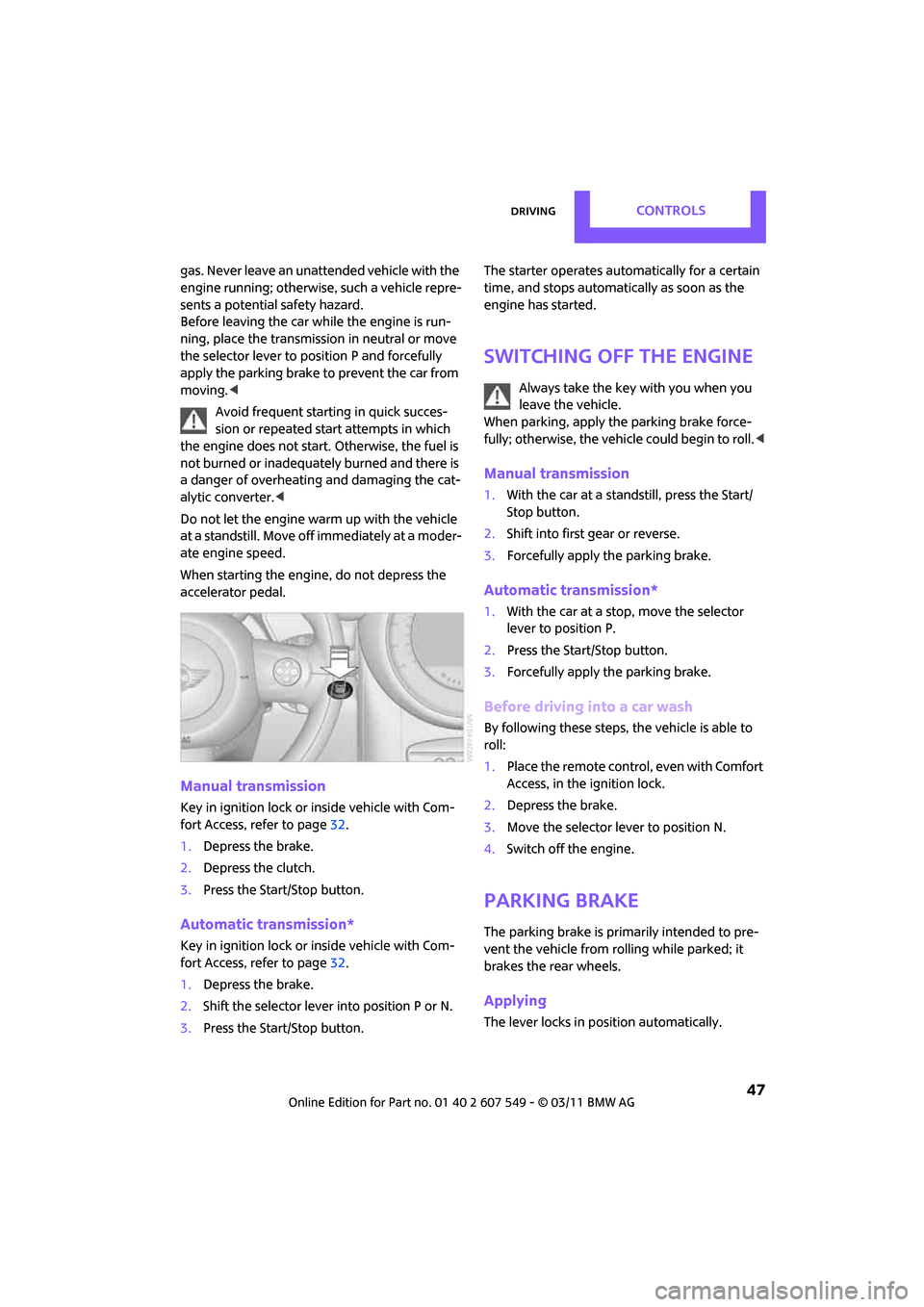
Manual transmission
Key in ignition lock or inside vehicle with Com-
fort Access, refer to page 32.
1. Depress the brake.
2. Depress the clutch.
3. Press the Start/Stop button.
Automatic transmission*
Key in ignition lock or inside vehicle with Com-
fort Access, refer to page 32.
1. Depress the brake.
2. Shift the selector lever into position P or N.
3. Press the Start/Stop button. The starter operates auto
matically for a certain
time, and stops automatically as soon as the
engine has started.
Switching off the engine
Always take the key with you when you
leave the vehicle.
When parking, apply the parking brake force-
fully; otherwise, the vehicle could begin to roll. <
Manual transmission
1.With the car at a standstill, press the Start/
Stop button.
2. Shift into first gear or reverse.
3. Forcefully apply the parking brake.
Automatic transmission*
1.With the car at a stop, move the selector
lever to position P.
2. Press the Start/Stop button.
3. Forcefully apply the parking brake.
Before driving into a car wash
By following these steps, the vehicle is able to
roll:
1.Place the remote control, even with Comfort
Access, in the ig nition lock.
2. Depress the brake.
3. Move the selector lever to position N.
4. Switch off the engine.
Parking brake
The parking brake is primarily intended to pre-
vent the vehicle from rolling while parked; it
brakes the rear wheels.
Applying
The lever locks in position automatically.
Page 90 of 254
CONTROLSPractical interior accessories
88
Practical interior accessories
Integrated universal
remote control*
The concept
The integrated universal remote control can
replace as many as three hand-held transmitters
for various remote-controlled devices, such as
garage and gate openers and lighting systems.
The integrated universal remote control regis-
ters and stores signals from the original hand-
held transmitters.
The signal of an original hand-held transmitter
can be programmed on one of the three mem-
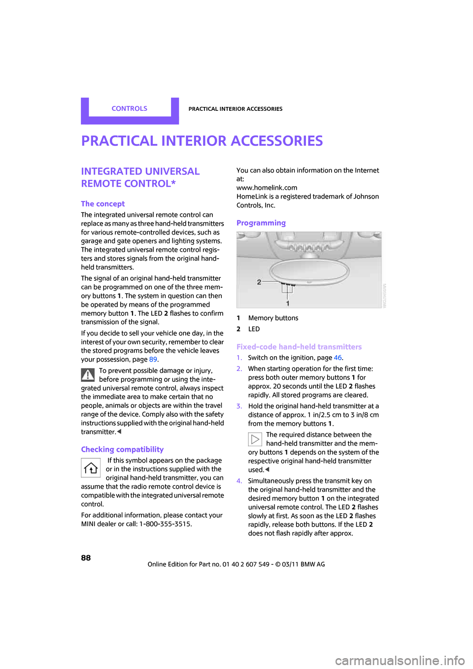
ory buttons 1. The system in question can then
be operated by means of the programmed
memory button 1. The LED 2 flashes to confirm
transmission of the signal.
If you decide to sell your vehicle one day, in the
interest of your own security, remember to clear
the stored programs before the vehicle leaves
your possession, page 89.
To prevent possible damage or injury,
before programming or using the inte-
grated universal remote control, always inspect
the immediate area to make certain that no
people, animals or object s are within the travel
range of the device. Comply also with the safety
instructions supplied with the original hand-held
transmitter. <
Checking compatibility
If this symbol a ppears on the package
or in the instructions supplied with the
original hand-held transmitter, you can
assume that the radio remote control device is
compatible with the integrated universal remote
control.
For additional informatio n, please contact your
MINI dealer or call: 1-800-355-3515. You can also obtain info
rmation on the Internet
at:
www.homelink.com
HomeLink is a registered trademark of Johnson
Controls, Inc.
Programming
1 Memory buttons
2 LED
Fixed-code hand-held transmitters
1.Switch on the ignition, page 46.
2. When starting operation for the first time:
press both outer memory buttons 1 for
approx. 20 seconds until the LED 2 flashes
rapidly. All stored programs are cleared.
3. Hold the original hand-held transmitter at a
distance of approx. 1in/2.5cm to 3in/8cm
from the memory buttons 1.
The required distance between the
hand-held transmitter and the mem-
ory buttons 1 depends on the system of the
respective original hand-held transmitter
used. <
4. Simultaneously press the transmit key on
the original hand-hel d transmitter and the
desired memory button 1 on the integrated
universal remote control. The LED 2 flashes
slowly at first. As soon as the LED 2 flashes
rapidly, release both buttons. If the LED 2
does not flash rapidly after approx.
Page 120 of 254
NAVIGATIONRoute guidance
118
Route guidance
Starting route guidance
1."Navigation"
2. "Enter address"
3. Select the destination.
4. "Accept destination"
5. "Start guidance"
> The route is displayed on the on-board com-
puter.
> The distance to the destination/intermedi-
ate destination and the estimated time of
arrival are displayed in the map view.
> The arrow display is displayed on the on-
board computer, if so desired.
Terminating route
guidance
In the arrow or map view
1."Navigation"
2. "Map"
3. Select the symbol.
4. "Stop guidance"
Continuing route
guidance
If the destination was not reached during the
last trip, route guidance can be resumed.
"Resume guidance"
Route criteria
General information
>You can influence the calculated route by
selecting certain criteria.
> Route criteria can be changed during desti-
nation input and during route guidance.
> Street types are part of the navigation data
and are taken into account in route plan-
ning, e.g. avoiding highways.
> The proposed route can differ from personal
experience.
> The settings are stored for the remote con-
trol currently in use.
> Route guidance with traffic information,
refer to page 124.
Changing route criteria
1."Navigation"
2. "Map"
3. "Route preference"
4. Selecting a criterion:
> "Fast route": time-optimized route
through a combination of the least possi-
Page 123 of 254
Route guidanceNAVIGATION
121
>Red road sign: the obstruction relates to the
planned route or direction of travel.
> Gray road sign: the obstruction does not
relate to the planned route or direction of
travel.
Traffic information, refer to page 122.
Planned route
After route guidance is started, the planned
route is displayed on the map.
Status boxes
Show/hide: press the MINI joystick.
>Upper status box: time, phone details, and
entertainment details.
> Lower status box: symbol for active route
guidance, traffic inform ation status, arrival
time, and distance from destination.
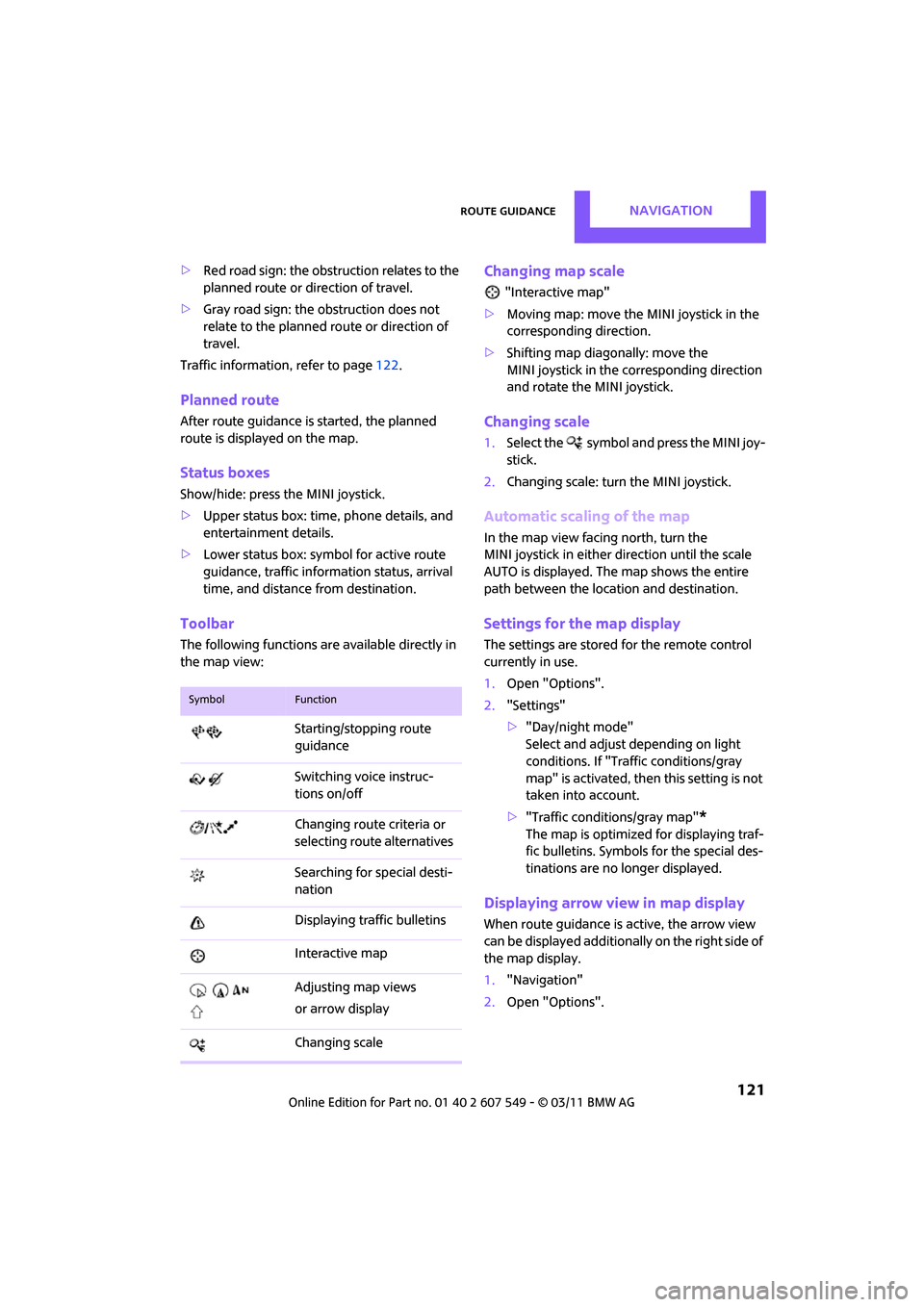
Toolbar
The following functions ar e available directly in
the map view:
Changing map scale
"Interactive map"
> Moving map: move the MINI joystick in the
corresponding direction.
> Shifting map diag onally: move the
MINI joystick in the corresponding direction
and rotate the MINI joystick.
Changing scale
1. Select the symbol and press the MINI joy-
stick.
2. Changing scale: turn the MINI joystick.
Automatic scaling of the map
In the map view facing north, turn the
MINI joystick in either direction until the scale
AUTO is displayed. The map shows the entire
path between the location and destination.
Settings for the map display
The settings are stored for the remote control
currently in use.
1.Open "Options".
2. "Settings"
>"Day/night mode"
Select and adjust depending on light
conditions. If "Traffic conditions/gray
map" is activated, then this setting is not
taken into account.
> "Traffic conditions/gray map"
*
The map is optimized for displaying traf-
fic bulletins. Symbols for the special des-
tinations are no longer displayed.
Displaying arrow view in map display
When route guidance is active, the arrow view
can be displayed additionally on the right side of
the map display.
1. "Navigation"
2. Open "Options".
SymbolFunction
Starting/stopping route
guidance
Switching voice instruc-
tions on/off
Changing route criteria or
selecting rout e alternatives
Searching for special desti-
nation
Displaying traffic bulletins
Interactive map
Adjusting map views
or arrow display
Changing scale
Page 239 of 254
Everything from A to ZREFERENCE
237
B
Background lighting, refer to
Ambient lighting 82
Backrests, refer to Seats 38
Backup lamps
– replacing bulb 211
Band-aids, refer to First aid pouch 218
Bar, refer to Tow-starting,
towing away 220
Base plate for telephone or mobile phone
– refer to Snap-in adapter 174
Bass sounds, refer to Tone control 131
Battery 216
– charging 216
– disposal 34,216
– jump-starting 218
– temporary power failure 216
Battery renewal
– remote control 34
Being towed 220
Belt tensioner, refer to Safety
belts 40
Belts, refer to Safety belts 40
Beverage holders, refer to
Cupholders 92
Black ice, refer to External
temperature warning 56
Blower, refer to Air flow rate 84,86
Bluetooth, activating/ deactivating 154,164
Bluetooth audio 146
– device pairing 146
– disconnecting an audio connection 148
– playback 147
– unpairing device 148
– What to do if... 148
Bottle holders, refer to Cupholders 92
Brake Assist 67
Brake fluid, refer to Service requirements 59 Brake lamps
– replacing bulbs
211
Brake pads, breaking in 96
Brake rotors 97
– brakes 96
– breaking in 96
Brake system 96
– breaking in 96
– disc brakes 97
– MINI Maintenance
System 202
Brakes
– ABS 67
– b
reaking in 96
– MINI Maintenance System 202
– parking brake 47
– service requirements 59
Brakes, refer to Braking
safely 97
Breakdown service, refer to Roadside Assistance 218
Break-in period 96
Breaking in the clutch 96
Brightness of Control
Display 65
Bulb changing, refer to Lamps and bulbs 208
Button for starting the engine 46
Buttons on the steering wheel 11
C
Calendar 179
– displaying appointment 180
– selecting calendar day 180
California Proposition 65
warning 5
Call
– accepting 157,168
– ending 157,168
– muting the microphone 158,170
– rejecting 157,168 Calling, refer to Phone
numbers, dialing 157,169
Can holders, refer to Cupholders 92
Capacities 226
Car battery, refer to Vehicle battery 216
Car care 204
Car key, refer to Keys/remote controls 26
Car phone
– installation location, refer to Center armrest 91
Car phone, refer to Telephone 154,163
Car radio, refer to Radio 132
Car wash
– before driving in 47
Car wash, care 204
Car washes 204
Care 204
– car washes 204
– car-care products 204
– CD/DVD drives 207
– external 204
– high-pressure washers 205
– internal 206
– leather 206
– manual washing 205
– upholstery and fabrics 206
– windows 205
– wiper blades 205
Cargo area 98
– capacity 226
– Comfort Access 33
– lamp 82
– opening from outside 30
– trunk lid, refer to Liftgate 30
Cargo area, expanding 98
Cargo area lamp 82
Cargo area li
d, refer to
Liftgate 30
Cargo area partition net, refer to Cargo net 100