Locking MINI Countryman 2014 (Mini Connected) User Guide
[x] Cancel search | Manufacturer: MINI, Model Year: 2014, Model line: Countryman, Model: MINI Countryman 2014Pages: 282, PDF Size: 6.76 MB
Page 58 of 282

DrivingVehicle equipmentThis chapter describes all series equipment as
well as country-specific and special equipment
offered for this model series.Therefore, it also
describes equipment that may not be found in
your vehicle, for instance due to the selected
special equipment or the country version. This
also applies to safety-related functions and sys‐
tems.
Ignition lock Insert the remote control into the
ignition lock
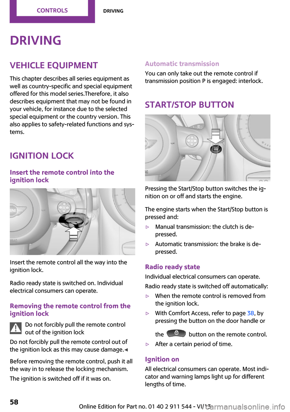
Insert the remote control all the way into the
ignition lock.
Radio ready state is switched on. Individual
electrical consumers can operate.
Removing the remote control from the
ignition lock
Do not forcibly pull the remote control
out of the ignition lock
Do not forcibly pull the remote control out of
the ignition lock as this may cause damage. ◀
Before removing the remote control, push it all
the way in to release the locking mechanism.
The ignition is switched off if it was on.
Automatic transmission
You can only take out the remote control if
transmission position P is engaged: interlock.
Start/Stop button
Pressing the Start/Stop button switches the ig‐
nition on or off and starts the engine.
The engine starts when the Start/Stop button is
pressed and:
▷Manual transmission: the clutch is de‐
pressed.▷Automatic transmission: the brake is de‐
pressed.
Radio ready state
Individual electrical consumers can operate.
Radio ready state is switched off automatically:
▷When the remote control is removed from
the ignition lock.▷With Comfort Access, refer to page 38, by
pressing the button on the door handle or
the
button on the remote control.
▷After a certain period of time.
Ignition on All electrical consumers can operate. Most indi‐
cator and warning lamps light up for different
lengths of time.
Seite 58ControlsDriving58
Online Edition for Part no. 01 40 2 911 544 - VI/13
Page 67 of 282

Manually unlocking the selector lever
lock
If the selector lever is locked in position P al‐
though the ignition is switched on, the brake is
depressed, and the button on the selector lever
is pressed, the selector lever lock can be over‐
ridden:1.Switch off the ignition.2.Unclip the sleeve of the selector lever.3.Pull the sleeve up over the selector lever
until the sleeve is inside out.
Pull off the plug-in cable connector if nec‐
essary.4.Insert the pulling hook 1 into the loop on
the passenger side.
The pulling hook is found in the vehicle
document portfolio or in the pouch of the
wheel change set, refer to page 245.5.Pull the loop upward.6.Move the selector lever into the desired po‐
sition, pressing the button on the front of
the selector lever.
Set the handbrake
Before manually unlocking the selector
lever lock, pull the handbrake firmly; otherwise,
the vehicle may roll away and cause personal
injury or property damage. ◀
Seite 67DrivingControls67
Online Edition for Part no. 01 40 2 911 544 - VI/13
Page 93 of 282

Driving stability control systemsVehicle equipment
This chapter describes all series equipment as
well as country-specific and special equipment
offered for this model series.Therefore, it also
describes equipment that may not be found in
your vehicle, for instance due to the selected
special equipment or the country version. This
also applies to safety-related functions and sys‐
tems.
Antilock Brake System
ABS
ABS prevents locking of the wheels duringbraking.
Steerability is maintained even during full brak‐
ing. This increases active driving safety.
ABS is operational every time you start the en‐
gine.
Electronic brake-force distribution EBVThe system controls the brake pressure in the
rear wheels to ensure stable braking behavior.
CBC Cornering Brake Control
When braking in curves or during a lane
change, driving stability and steering response
are improved further.
Brake assistant When the brakes are applied rapidly, this sys‐
tem automatically produces the maximum
braking force boost. In this way, the system
helps keep the braking distance as short as
possible. This system utilizes all of the benefits
provided by ABS.Do not reduce the pressure on the brake pedal
for the duration of full braking.
Dynamic Stability Con‐
trol DSC
The concept
DSC prevents traction loss in the driving wheels
when driving away and accelerating.
DSC also recognizes unstable vehicle condi‐
tions, such as fishtailing or nose-diving. Subject
to physical limits, DSC helps to keep the vehicle
on a steady course by reducing engine speed
and by applying brakes to the individual
wheels.
DSC is operational every time you start the en‐
gine.
Adjust your driving style to the situation
An appropriate driving style is always the
responsibility of the driver.
The laws of physics cannot be repealed, even
with DSC.
Do not reduce the additional safety margin
with a risky driving style, as otherwise there is a
risk of an accident. ◀
Deactivating DSC
Press the switch until the DSC OFF indicator
lamp lights up in the speedometer and DSC OFF
Seite 93Driving stability control systemsControls93
Online Edition for Part no. 01 40 2 911 544 - VI/13
Page 111 of 282

Before beginning with the mounting of a child
restraint fixing system, note the instructions,
refer to page 53.1.Hold the top of the backrest, for example
the head restraint, and pull on the loop, ar‐
row.2.Engage the backrest in the desired position
or fold it down.
Folding the backrests back up
Locking the backrest
When folding back, ensure that the locks
engage properly; otherwise, cargo could be
catapulted forward into the passenger com‐
partment during braking maneuvers and
swerving, endangering the occupants. ◀
No child restraint fixing systems
Do not mount child restraint fixing sys‐
tems in the rear when the rear seat backrests
are adjusted to a more vertical position; other‐
wise, the protection provided by these systems
may be reduced. ◀
When the backrests are folded back up, they
engage in the transport position.
To set the desired backrest inclination or com‐
fort position, hold the backrest, pull the loop
forward, and adjust the backrest.
MINI Paceman: rear seat backrests
Danger of pinching
Before folding down the rear seat back‐
rests, ensure that path of movement of the
backrests is clear; otherwise, injuries or damage
may result. ◀1.Pull on the respective loop, arrow.
The backrest is unlocked.2.Fold the backrest forward.
Folding the backrests back up Hold the top of the backrest, for example the
head restraint, and fold it back.
Locking the backrest
When folding back, ensure that the locks
engage properly; otherwise, cargo could be
catapulted forward into the passenger com‐
partment during braking maneuvers and
swerving, endangering the occupants. ◀
Flat loading floor Maximum load
Do not exceed the maximum load of
330 lbs, 150 kg, on the loading floor; otherwise,
damage may result. ◀
Access to storage area A storage area for items like the partition net is
found under the loading floor.
1.Reach into the recess, arrow 1, on the rear
edge of the loading floor.Seite 111Interior equipmentControls111
Online Edition for Part no. 01 40 2 911 544 - VI/13
Page 147 of 282

3."New route for"4.Turn the MINI joystick. Enter the number of
kilometers within which you would like to
return to the original route.5.Press the MINI joystick.
Resuming the original route
If the route section should no longer be by‐
passed:
1."Navigation"2."Route information"3."New route for:"4."Remove blocking"
Gas station recommenda‐
tion
The remaining range is calculated and gas sta‐
tions along the route are displayed if needed.
Even with the latest navigation data, informa‐
tion on individual special destinations may
have changed; for example, gas stations might
not be in operation.
1."Navigation"2."Route information"3."Recommended refuel"
A list of the gas stations is displayed.4.Highlight a gas station.5.Select the gas station.6. Select the symbol.7."Start guidance": destination guidance to
the selected gas station is started.
"Add as another destination": the gas sta‐
tion is added to the route.
Destination guidance
through voice instruc‐
tions
Switching spoken instructions on/off The spoken instructions can be switched on or
off during destination guidance.
The setting is stored for the remote control cur‐
rently in use.
1."Navigation"2."Map"3. Select the symbol.SymbolFunction The spoken instructions are switched
on. Spoken instructions are switched off.
Repeating a spoken instruction
1."Navigation"2."Map"3. Highlight the symbol.4.Press the MINI joystick twice.
Volume of spoken instructions
Turn the volume knob while giving an instruc‐
tion until the desired volume is set.
Seite 147Destination guidanceNavigation147
Online Edition for Part no. 01 40 2 911 544 - VI/13
Page 216 of 282

RefuelingVehicle equipmentThis chapter describes all series equipment as
well as country-specific and special equipment
offered for this model series.Therefore, it also
describes equipment that may not be found in
your vehicle, for instance due to the selected
special equipment or the country version. This
also applies to safety-related functions and sys‐
tems.
General information Refuel promptly
At the latest, refuel at a range below
30 miles/50 km; otherwise, the engine function
is not ensured and damage may occur. ◀
Notes Switch off the engine before refueling
Always switch off the engine before refu‐
eling; otherwise, fuel cannot be added to the
tank and a message will be displayed. ◀
Observe when handling fuel▷Take all precautionary measures and
observe all applicable regulations
when handling fuel.▷Do not carry any spare fuel containers in
your vehicle. They can develop a leak and
cause an explosion or cause a fire in the
event of an accident. ◀
Fuel cap
Opening
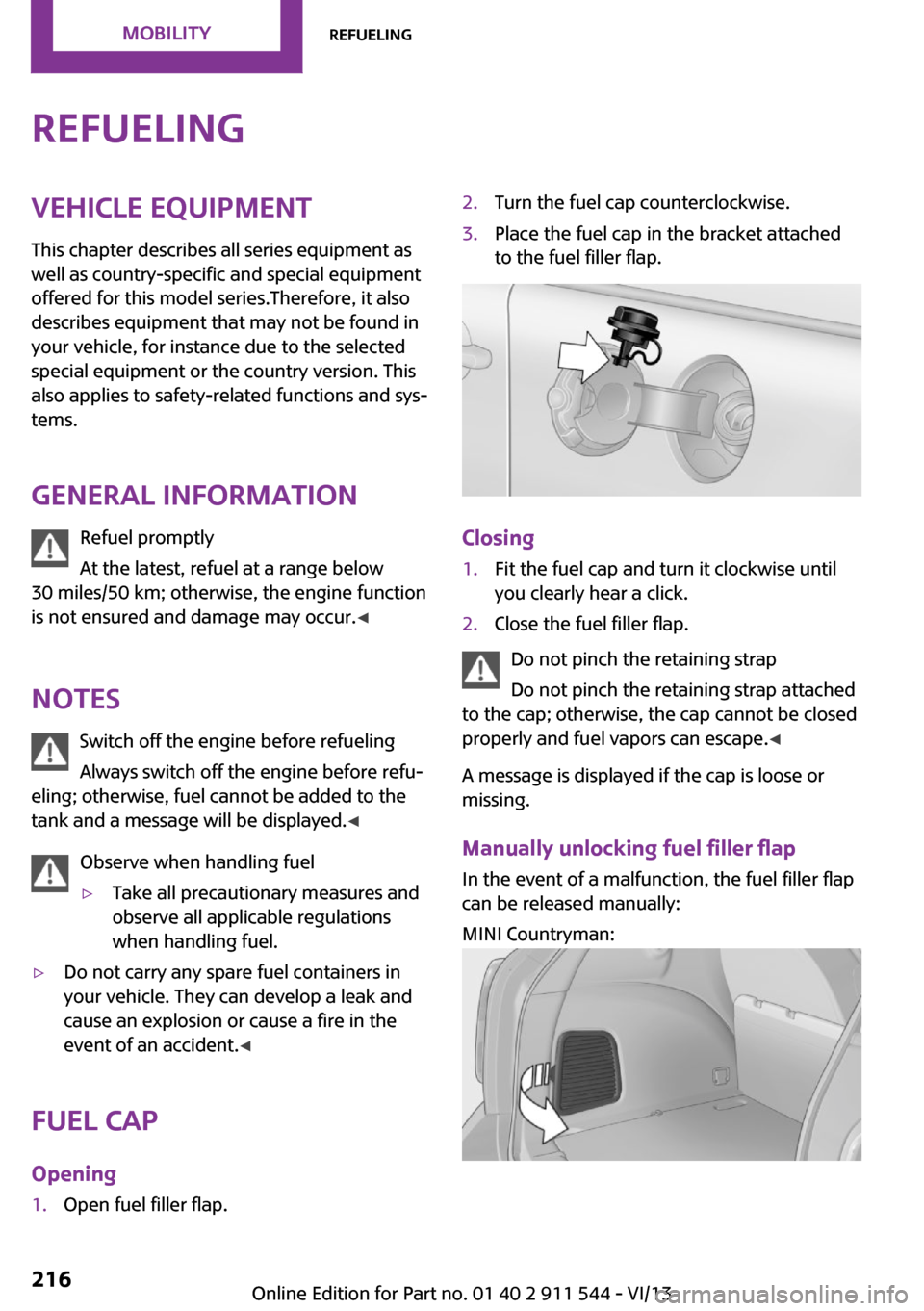
1.Open fuel filler flap.2.Turn the fuel cap counterclockwise.3.Place the fuel cap in the bracket attached
to the fuel filler flap.
Closing
1.Fit the fuel cap and turn it clockwise until
you clearly hear a click.2.Close the fuel filler flap.
Do not pinch the retaining strap
Do not pinch the retaining strap attached
to the cap; otherwise, the cap cannot be closed
properly and fuel vapors can escape. ◀
A message is displayed if the cap is loose or
missing.
Manually unlocking fuel filler flap In the event of a malfunction, the fuel filler flap
can be released manually:
MINI Countryman:
Seite 216MobilityRefueling216
Online Edition for Part no. 01 40 2 911 544 - VI/13
Page 233 of 282

To avoid damage, make sure that the
wiper arms are resting against the wind‐
shield before you open the engine compart‐
ment. Do not open the engine hood before the
engine has cooled down; otherwise, injuries
may result. ◀
Unlocking and opening the hood1.Pull the lever.2.Lift the hood all the way.3.Press the release handle and open the
hood.
Danger of injury when the hood is open
There is a danger of injury from protrud‐
ing parts when the hood is open. ◀
Closing the hood
Close the hood from a height of ap‐
prox. 16 in/40 cm with momentum. It must be
clearly heard to engage.
Hood open when driving
If you see any signs that the hood is not
completely closed while driving, pull over im‐
mediately and close it securely. ◀
Danger of pinching
Make sure that the closing path of the
hood is clear; otherwise, injuries may result. ◀
Seite 233Engine compartmentMobility233
Online Edition for Part no. 01 40 2 911 544 - VI/13
Page 239 of 282

Replacing componentsVehicle equipmentThis chapter describes all series equipment as
well as country-specific and special equipment
offered for this model series.Therefore, it also
describes equipment that may not be found in
your vehicle, for instance due to the selected
special equipment or the country version. This
also applies to safety-related functions and sys‐
tems.
Wiper blade replacement General information Do not fold down the wipers without
wiper blades
Do not fold down the wipers if wiper blades
have not been installed; this may damage the
windshield. ◀
Replacing the front wiper blades1.Fold up and hold the wiper arm.2.Squeeze the locking spring, arrows 1, and
fold out the wiper blade, arrow 2.3.Take the wiper blade out of the catch
mechanism toward the front.4.Press the new wiper blade into the fixation
until it engages audibly.5.Fold down the wiper arm.Risk of damage
Before opening the hood, ensure that the
wiper arms with wiper blades are folded onto
the window; otherwise, damage may occur. ◀
Replacing the rear wiper blade
MINI Countryman:
MINI Paceman:
1.Fold up and hold the wiper arm.2.Turn the wiper blade all the way back, ar‐
row.3.Press the wiper blade against the stop to
push it out of the fixation.4.Press the new wiper blade into the fixation
until it engages audibly.5.Fold down the wiper arm.Seite 239Replacing componentsMobility239
Online Edition for Part no. 01 40 2 911 544 - VI/13
Page 271 of 282

Bluetooth connection, activat‐ing/deactivating 181, 191
Bluetooth hands-free sys‐ tem 180
Brake assistant 93
Brake discs, breaking in 122
Brake fluid, refer to Service re‐ quirements 74
Brake force distribution, elec‐ tronic 93
Brake pads, breaking in 122
Brakes– Handbrake 60
Brakes, MINI maintenance
system 237
Brakes, service require‐ ments 74
Brake system, MINI mainte‐ nance system 237
Braking, notes 123
Breakdown assistance, Road‐ side Assistance 248
Breaking in 122
Brightness on the Control Dis‐ play 74
Buckle tongue, rear
– Height adjustment 48
Button for starting the engine,
refer to Start/Stop button 58
C
Calendar 206
California Proposition 65 Warning 7
Car battery, refer to Vehicle battery 246
Car care products 255
Care, displays 257
Care, vehicle 255
Cargo area
– Comfort Access 39– Flat loading floor 111– Multi-function hook 113– Opening from the out‐
side 37– Partition net 112Cargo area, enlarging– Cargo cover 110
Cargo area lamp, refer to Inte‐
rior lamps 81
Cargo area tailgate, refer to Tailgate 37
Car horn, refer to Horn 14
Carpet, care 257
Car phone, refer to Tele‐ phone 180, 190
Car wash 254
CBC, Cornering Brake Con‐
trol 93
CBS Condition Based Serv‐ ice 237
CD 166
CD/DVD drives, care 257
CD player 166
Center armrest 115
Center console, refer to Around the center con‐
sole 18
Center rail 116
Center rail, refer to Storage compartments 116
Central locking
– Comfort Access 38– From the inside 36– From the outside 34
Central locking system
– Concept 33– From the outside 33
Central screen, see Control
Display 20
Changes, technical, refer to Safety 7
Changing wheels/tires 227
Check Control 75
Children, transporting 53
Child restraint fixing system LATCH 54
Child restraint fixing sys‐ tems 53
Child restraint fixing systems, mounting 53
Child seat, mounting 53
Child seats, refer to Transport‐
ing children safely 53
Chrome parts, care 257
Circulation of air, refer to Re‐ circulated air
mode 100, 102
Cleaning, displays 257
Cleaning, refer to Care 254
Climate 99
Climate mode– Ventilation 103
Clock 68
Clock
– 12h/24h format 72– Setting the time and date 72
Closing
– From the inside 36– From the outside 34
Clutch, breaking in 122
Cockpit 14
Cold start, refer to Starting the engine 59
Combination instrument, refer to Displays 16
Combination switch, refer to Turn signal/high beams/
headlamp flasher 61
Combination switch, refer to Washer/wiper system 61
Comfort Access
– In the car wash 40– Replacing the battery 41
Comfort area, refer to Around
the center console 18
Compartment for remote con‐ trol, refer to Ignition lock 58
Compass, digital 106
Computer 69
Computer, displaying informa‐ tion 69
Condition Based Service CBS 237
Confirmation signals for vehi‐ cle locking/unlocking 35
Connecting, mobile phone, re‐ fer to Pairing the mobile
phone 180, 191
Seite 271Everything from A to ZReference271
Online Edition for Part no. 01 40 2 911 544 - VI/13
Page 272 of 282

Consumption, refer to Aver‐age fuel consumption 70
Contacts 187, 203
Control Display 20
Control Display, care 257
Control Display, settings 73
Controls and displays 14
Control systems, driving stabil‐ ity 93
Convenient operation– Windows 34
Coolant temperature 69
Cooling function, switching on and off 103
Cooling, maximum 102
Cornering Brake Control, CBC 93
Corrosion on brake discs 124
Cradle for telephone or mobile phone, refer to Snap-in
adapter 200
Cruise control 96
Cupholders 108
Current fuel consumption 70
Current location, storing 138
Curve lights, refer to Adaptive Light Control 80
Cylinders, number of, refer to Engine data 260
D
Dashboard lighting, refer to Instrument lighting 80
Dashboard, refer to Cock‐ pit 14
Dashboard, refer to Dis‐ plays 16
Data, technical 260
Date
– Date format 73– Setting 73
Daytime running lights 79
Decorative trim, care 257
Defogging windows 100
Defroster
– Rear window 100, 103Defrosting windows 100
Defrost setting, refer to De‐ frosting windows 100
Destination entry via the ad‐ dress book 138
Destination guidance with in‐ termediate destinations 143
Destination input, naviga‐ tion 136
Digital compass 106
Digital radio 159
Dip stick, engine oil 234
Directional indicators, refer to Turn signals 61
Displacement, refer to Engine data 260
Display lighting, refer to In‐ strument lighting 80
Displays 16
Displays and controls 14
Displays, care 257
Displays, cleaning 257
Displays, refer to Instrument cluster 16
Disposal– Remote control battery 41
Distance warning, refer to
Park Distance Control
PDC 97
Door key, refer to Remote control with integrated
key 32
Door lock 35
Door lock, confirmation sig‐ nals 35
Doors, manual operation 36
Doors, unlocking and locking
– Confirmation signals 35– From the inside 36– From the outside 34
DOT Quality Grades 224
Drive-off assistant, refer to Hill drive-off assistant 95
Driving notes, breaking in 122
Driving off on hills, refer to Hill drive-off assistant 95
Driving on poor roads 125
Driving stability control sys‐ tems 93
Driving tips, refer to Driving notes 122
Dry air, refer to Cooling func‐ tion 103
DSC Dynamic Stability Con‐ trol 93
DTC Dynamic Traction Con‐ trol 94
DTMF suffix dialing 185, 197
Dynamic destination guid‐ ance 152
Dynamic Stability Control DSC 93
Dynamic Traction Control DTC 94
E Electrical malfunction– Door lock 36– Fuel filler flap 216
Electronic brake-force distri‐
bution 93
Electronic Stability Program ESP, refer to Dynamic Stabil‐
ity Control DSC 93
Emergency activation
– Automatic transmission, re‐
fer to Overriding selector
lever lock 67
Emergency operation, fuel
filler flap, unlocking man‐
ually 216
Emergency operation, refer to
Manual operation
– Door lock 36
Energy, saving, refer to Saving
fuel 130
Engine, breaking in 122
Engine compartment 232
Engine oil, adding 234
Engine oil, additives, refer to Approved engine oils 235
Seite 272ReferenceEverything from A to Z272
Online Edition for Part no. 01 40 2 911 544 - VI/13