Engine light MINI Countryman 2014 (Mini Connected) Owner's Guide
[x] Cancel search | Manufacturer: MINI, Model Year: 2014, Model line: Countryman, Model: MINI Countryman 2014Pages: 282, PDF Size: 6.76 MB
Page 124 of 282
Pulsation of the brake pedal and sounds from
the hydraulic circuits indicate that ABS is in its
active mode.
Do not let your foot rest on the brake
pedal
Do not drive with your foot resting on the brake
pedal. Even light but consistent pedal pressure
can lead to high temperatures, brake wear and
possibly even brake failure. ◀
Objects in the area around the pedals No objects in the area around the pedals
Keep floor mats, carpets, and any other
objects out of the area of motion of the pedals;
otherwise, the function of the pedals could be
impeded while driving
Do not place additional floor mats over existing
mats or other objects.
Only use floor mats that have been approved
for the vehicle and can be properly fixed in
place.
Ensure that the floor mats are securely fastened
again when they are returned after being re‐
moved, such as for cleaning. ◀
Driving in wet conditions
When roads are wet or there is heavy rain, briefly exert gentle pressure on the brake pedal
every few miles.
Ensure that this action does not endanger other
road users.
The heat generated in this process helps dry
the brake discs and pads.
In this way braking efficiency will be available
when you need it.
HillsDrive long or steep downhill gradients in the
gear in which the least braking is required. Oth‐
erwise, the brake system may overheat, result‐
ing in a reduction in the brake system effi‐
ciency.You can increase the engine's braking effect by
shifting down, going all the way to first gear, if
necessary.
Downshifting in manual mode of the automatic
transmission, refer to page 66.
Avoid load on the brakes
Avoid placing excessive load on the brake
system. Light but consistent brake pressure can
lead to high temperatures, brake wear and
possibly even brake failure. ◀
Do not drive in neutral
Never drive with the transmission in neu‐
tral, with the engine switched off or with the
clutch depressed; otherwise, you will have nei‐
ther the braking action of the engine or nor its
power assistance when braking or steering. ◀
Brake disc corrosion Corrosion on the brake discs and contamina‐
tion on the brake pads are furthered by:▷Low mileage.▷Extended periods when the vehicle is not
used at all.▷Infrequent use of the brakes.
Corrosion occurs when the minimum pressure
that must be exerted by the pads during brake
applications to clean the discs is not reached.
Should corrosion form on the brake discs, the
brakes will tend to respond with a pulsating ef‐
fect that generally cannot be corrected.
When the vehicle is parked
When using the automatic climate control, con‐
densation water develops that exits under‐
neath the vehicle.
Therefore, traces of condensed water under the
vehicle are normal.
After the engine is switched off, the coolant
pump may continue running for some time in
the MINI Cooper S. This causes noises in the en‐
gine compartment.
Seite 124Driving tipsThings to remember when driving124
Online Edition for Part no. 01 40 2 911 544 - VI/13
Page 130 of 282
Saving fuelVehicle equipment
This chapter describes all series equipment as
well as country-specific and special equipment
offered for this model series.Therefore, it also
describes equipment that may not be found in
your vehicle, for instance due to the selected
special equipment or the country version. This
also applies to safety-related functions and sys‐
tems.
General information Your vehicle contains advanced technology for
the reduction of fuel consumption and emis‐
sions.
Fuel consumption depends on a number of dif‐
ferent factors. The implementation of certain
measures, driving style and regular mainte‐ nance can have an influence on fuel consump‐
tion and on the environmental impact.
Remove unnecessary cargo Additional weight increases fuel consumption.
Remove attached parts following use Remove unneeded auxiliary mirrors, roof or
rear luggage racks after use.
Attached parts on the vehicle impair the aero‐
dynamics and increase the fuel consumption.
Close both windows Open windows causes higher air resistance and
thus increases fuel consumption.
Check the tire inflation pressure
regularly
Check and, if necessary, correct the tire infla‐
tion pressure, refer to page 220, at least twice
a month and before starting on a long trip.Low tire inflation pressure increases rolling re‐
sistance and thus raises fuel consumption and
tire wear.
Drive away without delayDo not wait for the engine to warm-up while
the vehicle remains stationary. Start driving
right away, but at moderate engine speeds.
This is the fastest way for the cold engine to
reach its operating temperature.
Look well ahead when driving Avoid unnecessary acceleration and braking. To
achieve this, maintain a suitable distance to the
vehicle driving ahead of you.
Driving smoothly and looking ahead reduces
fuel consumption.
Avoid high engine speeds Use 1st gear to get the vehicle in motion. Be‐
ginning with 2nd gear, accelerate rapidly. When
accelerating, shift up before reaching high en‐
gine speeds.
When you reach the desired speed, shift into
the highest applicable gear and drive with the
engine speed as low as possible and at a con‐
stant speed.
As a rule: driving at low engine speeds lowers
fuel consumption and reduces wear.
Use coasting conditions
When approaching a red light, take your foot
off the accelerator and coast to a halt in the
highest applicable gear.
On a downhill slope, take your foot off the ac‐
celerator and coast in a suitable gear.
The flow of fuel is interrupted while coasting.Seite 130Driving tipsSaving fuel130
Online Edition for Part no. 01 40 2 911 544 - VI/13
Page 131 of 282
Switch off the engine during longer
stops
Switch off the engine during longer stops, e.g.,
at traffic lights, railroad crossings or in traffic
congestion.
Fuel savings are already achieved after the en‐
gine is turned off for as little as 4 seconds.
Automatic Engine Start/Stop Function
The Automatic Engine Start/Stop Function auto‐
matically switches the engine off during a stop.
If the engine is stopped and then started again,
fuel consumption and emissions drop com‐
pared to an engine that runs permanently.
Stopping the engine even for just a few sec‐
onds can result in savings.
In addition, fuel consumption depends on other
factors as well, such as driving style, road con‐
ditions, maintenance, and environmental fac‐
tors.
Switch off any functions that are not currently needed
Functions such as seat heating and the rear
window defroster require a lot of energy and
consume additional fuel, especially in city and
stop-and-go traffic.
Therefore, switch off these functions if they are
not actually needed.
Have maintenance carried out
Have vehicles maintained regularly to achieve
optimal vehicle economy and operating life.
Have the maintenance carried out by the serv‐
ice center.
Please also note the MINI maintenance system,
refer to page 237.Seite 131Saving fuelDriving tips131
Online Edition for Part no. 01 40 2 911 544 - VI/13
Page 166 of 282

CD/multimediaVehicle equipment
This chapter describes all series equipment as
well as country-specific and special equipment
offered for this model series.Therefore, it also
describes equipment that may not be found in
your vehicle, for instance due to the selected
special equipment or the country version. This
also applies to safety-related functions and sys‐
tems.
Sound output Switching on/off
When the ignition is switched off: press ON/OFF
button on the radio.
Muting When the ignition is switched on or the engine
is running: press the ON/OFF button on the
radio.
This symbol at the upper edge of the Con‐
trol Display indicates that the sound is switched
off.
CD player
Playback
Inserting the CD
Insert the CD with the printed side facing up.
Playback begins automatically.
Reading can take a few minutes with com‐
pressed audio files.
Starting playback
A CD is contained in the CD player.1."CD/Multimedia"2."CD"3.Select the desired track. Press the MINI joy‐
stick to start playback.
Playable formats
▷CD: CD-ROM, CD-R, CD-RW, CD-DA.▷Compressed audio files: MP3, WMA, AAC.
Ejecting the CD
Press the button on the CD player.
The CD emerges slightly from the drive.
Seite 166EntertainmentCD/multimedia166
Online Edition for Part no. 01 40 2 911 544 - VI/13
Page 182 of 282
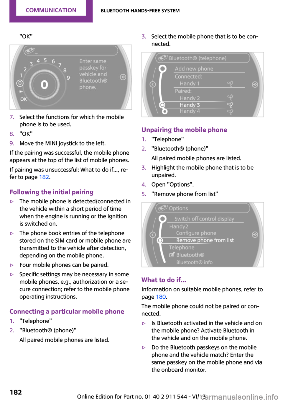
"OK"7.Select the functions for which the mobile
phone is to be used.8."OK"9.Move the MINI joystick to the left.
If the pairing was successful, the mobile phone
appears at the top of the list of mobile phones.
If pairing was unsuccessful: What to do if..., re‐
fer to page 182.
Following the initial pairing
▷The mobile phone is detected/connected in
the vehicle within a short period of time
when the engine is running or the ignition
is switched on.▷The phone book entries of the telephone
stored on the SIM card or mobile phone are
transmitted to the vehicle after detection,
depending on the mobile phone.▷Four mobile phones can be paired.▷Specific settings may be necessary in some
mobile phones, e.g., authorization or a se‐
cure connection; refer to the mobile phone
operating instructions.
Connecting a particular mobile phone
1."Telephone"2."Bluetooth® (phone)"
All paired mobile phones are listed.3.Select the mobile phone that is to be con‐
nected.
Unpairing the mobile phone
1."Telephone"2."Bluetooth® (phone)"
All paired mobile phones are listed.3.Highlight the mobile phone that is to be
unpaired.4.Open "Options".5."Remove phone from list"
What to do if...
Information on suitable mobile phones, refer to
page 180.
The mobile phone could not be paired or con‐
nected.
▷Is Bluetooth activated in the vehicle and on
the mobile phone? Activate Bluetooth in
the vehicle and on the mobile phone.▷Do the Bluetooth passkeys on the mobile
phone and the vehicle match? Enter the
same passkey on the mobile phone and via
the onboard monitor.Seite 182CommunicationBluetooth hands-free system182
Online Edition for Part no. 01 40 2 911 544 - VI/13
Page 193 of 282

If the pairing was successful, the mobile phone
appears at the top of the list of mobile phones.
The functions supported by the mobile phone
and audio device are displayed as symbols
when paired.
White symbol: the function is active.
Gray symbol: the function is inactive.SymbolFunction Telephone. Additional telephone. Audio source.
Four mobile phones can be paired with the ve‐
hicle at once. Three mobile phones can be con‐
nected with the vehicle at once.
If pairing was unsuccessful: What to do if..., re‐
fer to page 194.
Following the initial pairing
▷The mobile phone is detected/connected in
the vehicle within a short period of time
when the engine is running or the ignition
is switched on.▷The phone book entries of the telephone
stored on the SIM card or mobile phone are
transmitted to the vehicle after detection,
depending on the mobile phone.▷Specific settings may be necessary in some
mobile phones, e.g., authorization or a se‐
cure connection; refer to the mobile phone
operating instructions.
Connecting a particular mobile phone
1."Telephone"2."Bluetooth® (phone)"
All paired mobile phones are listed.3.Select the mobile phone that is to be con‐
nected.
The functions assigned to the mobile phone
before unpairing are assigned to the mobile
phone when it is reconnected. These functions
are deactivated in a mobile phone that is al‐
ready connected.
Device options Device options can be activated or deactivated
for paired and connected devices.
Configuring the mobile phoneAdditional functions can be activated or deacti‐
vated for paired and connected mobile phones.
1."Telephone"2."Bluetooth® (phone)"3.Highlight the mobile phone to be config‐
ured.4.Open "Options".5."Configure phone"6.At least one function must be selected.▷"Telephone"Seite 193Bluetooth mobile phone preparation packageCommunication193
Online Edition for Part no. 01 40 2 911 544 - VI/13
Page 230 of 282
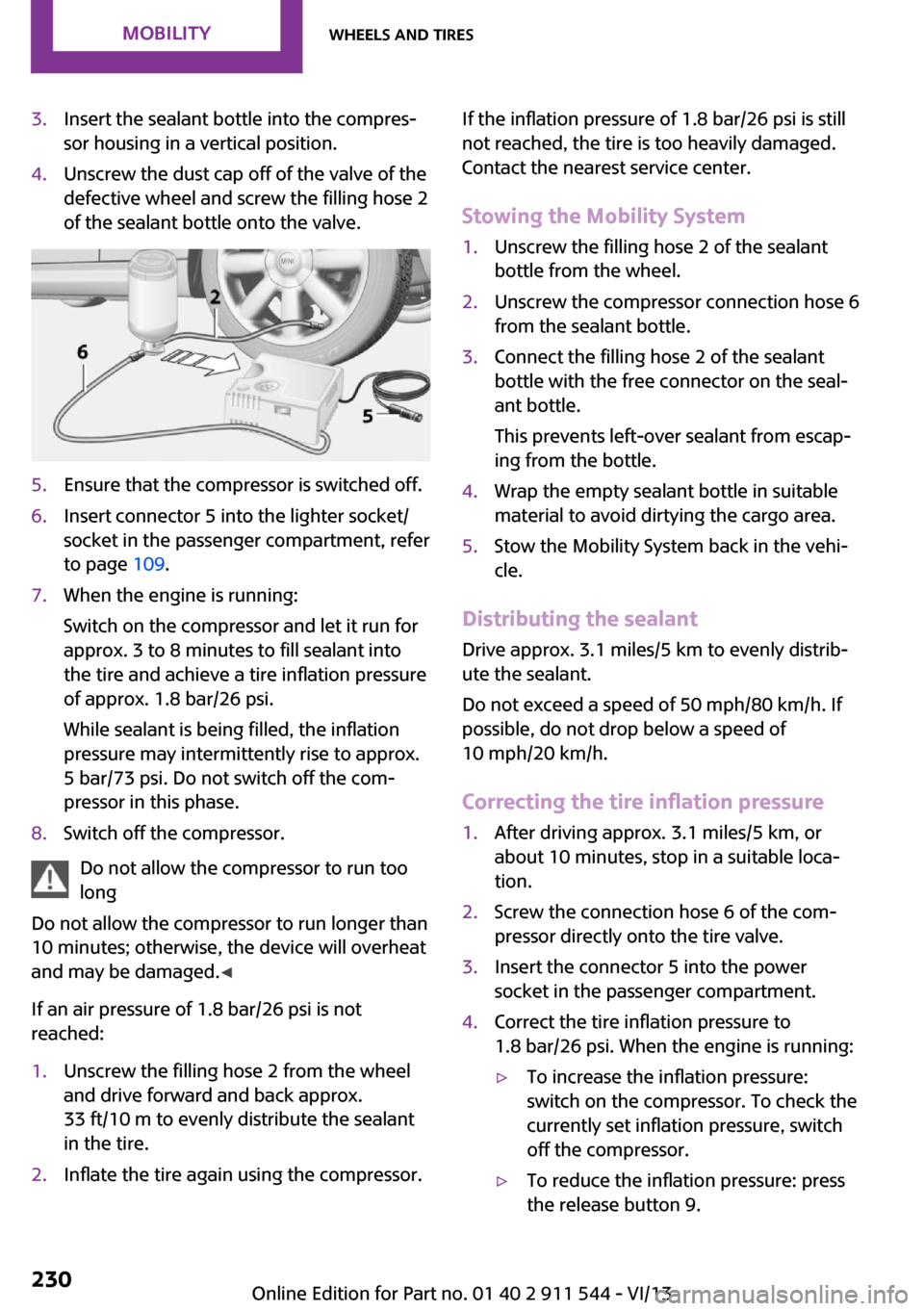
3.Insert the sealant bottle into the compres‐
sor housing in a vertical position.4.Unscrew the dust cap off of the valve of the
defective wheel and screw the filling hose 2
of the sealant bottle onto the valve.5.Ensure that the compressor is switched off.6.Insert connector 5 into the lighter socket/
socket in the passenger compartment, refer
to page 109.7.When the engine is running:
Switch on the compressor and let it run for
approx. 3 to 8 minutes to fill sealant into
the tire and achieve a tire inflation pressure
of approx. 1.8 bar/26 psi.
While sealant is being filled, the inflation
pressure may intermittently rise to approx.
5 bar/73 psi. Do not switch off the com‐
pressor in this phase.8.Switch off the compressor.
Do not allow the compressor to run too
long
Do not allow the compressor to run longer than
10 minutes; otherwise, the device will overheat
and may be damaged. ◀
If an air pressure of 1.8 bar/26 psi is not
reached:
1.Unscrew the filling hose 2 from the wheel
and drive forward and back approx.
33 ft/10 m to evenly distribute the sealant
in the tire.2.Inflate the tire again using the compressor.If the inflation pressure of 1.8 bar/26 psi is still
not reached, the tire is too heavily damaged.
Contact the nearest service center.
Stowing the Mobility System1.Unscrew the filling hose 2 of the sealant
bottle from the wheel.2.Unscrew the compressor connection hose 6
from the sealant bottle.3.Connect the filling hose 2 of the sealant
bottle with the free connector on the seal‐
ant bottle.
This prevents left-over sealant from escap‐
ing from the bottle.4.Wrap the empty sealant bottle in suitable
material to avoid dirtying the cargo area.5.Stow the Mobility System back in the vehi‐
cle.
Distributing the sealant
Drive approx. 3.1 miles/5 km to evenly distrib‐
ute the sealant.
Do not exceed a speed of 50 mph/80 km/h. If
possible, do not drop below a speed of
10 mph/20 km/h.
Correcting the tire inflation pressure
1.After driving approx. 3.1 miles/5 km, or
about 10 minutes, stop in a suitable loca‐
tion.2.Screw the connection hose 6 of the com‐
pressor directly onto the tire valve.3.Insert the connector 5 into the power
socket in the passenger compartment.4.Correct the tire inflation pressure to
1.8 bar/26 psi. When the engine is running:▷To increase the inflation pressure:
switch on the compressor. To check the
currently set inflation pressure, switch
off the compressor.▷To reduce the inflation pressure: press
the release button 9.Seite 230MobilityWheels and tires230
Online Edition for Part no. 01 40 2 911 544 - VI/13
Page 236 of 282
CoolantVehicle equipment
This chapter describes all series equipment as
well as country-specific and special equipment
offered for this model series.Therefore, it also
describes equipment that may not be found in
your vehicle, for instance due to the selected
special equipment or the country version. This
also applies to safety-related functions and sys‐
tems.
General information Danger of burns from hot engine
Do not open the cooling system while the
engine is hot; otherwise, escaping coolant may
cause burns. ◀
Suitable additives
Only use suitable additives; otherwise,
engine damage may occur. The additives are
harmful to your health. ◀
Coolant consists of water and additives.
Not all commercially available additives are
suitable for your MINI vehicle. Ask your service
center for suitable additives.
Coolant temperature
If the coolant and therefore the engine over‐
heat, a warning lamp lights up. A message ap‐
pears on the Control Display.
Coolant level Checking1.Do not open the hood until the engine has
cooled down.2.Turn the expansion tank cap counterclock‐
wise slightly to allow any accumulated
pressure to escape; then continue turning
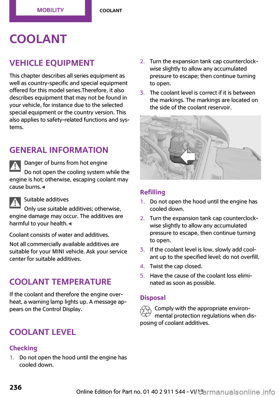
to open.3.The coolant level is correct if it is between
the markings. The markings are located on
the side of the coolant reservoir.
Refilling
1.Do not open the hood until the engine has
cooled down.2.Turn the expansion tank cap counterclock‐
wise slightly to allow any accumulated
pressure to escape, then continue turning
to open.3.If the coolant level is low, slowly add cool‐
ant up to the specified level; do not overfill.4.Twist the cap closed.5.Have the cause of the coolant loss elimi‐
nated as soon as possible.
Disposal
Comply with the appropriate environ‐mental protection regulations when dis‐
posing of coolant additives.
Seite 236MobilityCoolant236
Online Edition for Part no. 01 40 2 911 544 - VI/13
Page 238 of 282
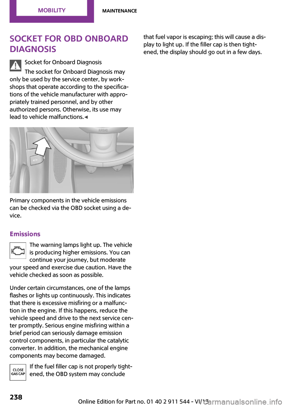
Socket for OBD Onboard
Diagnosis
Socket for Onboard Diagnosis
The socket for Onboard Diagnosis may
only be used by the service center, by work‐
shops that operate according to the specifica‐
tions of the vehicle manufacturer with appro‐
priately trained personnel, and by other
authorized persons. Otherwise, its use may
lead to vehicle malfunctions. ◀
Primary components in the vehicle emissions
can be checked via the OBD socket using a de‐
vice.
Emissions The warning lamps light up. The vehicle
is producing higher emissions. You can
continue your journey, but moderate
your speed and exercise due caution. Have the
vehicle checked as soon as possible.
Under certain circumstances, one of the lamps
flashes or lights up continuously. This indicates
that there is excessive misfiring or a malfunc‐
tion in the engine. If this happens, reduce the
vehicle speed and drive to the next service cen‐
ter promptly. Serious engine misfiring within a
brief period can seriously damage emission
control components, in particular the catalytic
converter. In addition, the mechanical engine
components may become damaged.
If the fuel filler cap is not properly tight‐
ened, the OBD system may conclude
that fuel vapor is escaping; this will cause a dis‐
play to light up. If the filler cap is then tight‐
ened, the display should go out in a few days.Seite 238MobilityMaintenance238
Online Edition for Part no. 01 40 2 911 544 - VI/13
Page 246 of 282
Vehicle batteryMaintenance
The battery is maintenance-free, i.e., the elec‐
trolyte will last for the life of the battery in tem‐
perate climate conditions.
The service center will be happy to answer any
questions on the battery.
Battery replacement Use approved vehicle batteries
Only use vehicle batteries that have been
approved for your vehicle by the manufacturer;
otherwise, the vehicle could be damaged and
systems or functions may not be fully availa‐
ble. ◀
Have the vehicle battery registered by the serv‐
ice center after it is replaced to ensure that all
comfort functions are available without restric‐
tions and that any associated Check Control
messages are no longer displayed.
Charging the battery
Note Do not connect the charger to the socket
Do not connect the battery charger to the
socket installed in the vehicle at the factory as
this could damage the battery. ◀
Only charge the battery in the vehicle when the engine is switched off. Connections, refer to
page 248.
General information Ensure that the battery is sufficiently charged to
achieve the full battery life.
It may be necessary to charge the battery in
the following cases:▷When the vehicle is frequently used to
travel short distances.▷When the vehicle has not been driven for
more than one month.Power failure
After a temporary power failure, some equip‐
ment will be restricted in its use and will need
to be reinitialized. In addition, certain individual
settings will be lost and must be updated:▷Time and date: the values must be up‐
dated, refer to page 72.▷Radio: the stations need to be stored again,
refer to page 159.▷Onboard monitor: full functionality will be
restored after some time.▷Glass sunroof, electrical: it may only be pos‐
sible to tilt the roof. The system needs to be
initialized. Contact the service center.
Indicator/warning lamps
Lights up red: the vehicle battery is no
longer being charged. Alternator mal‐
function.
Switch off all unnecessary electrical consumers.
Have the battery checked immediately.
Lights up yellow: the battery charge
level is very low, the battery is old, or it
is not securely connected.
Charge the battery by taking a long drive or us‐
ing an external charger. If the indicators appear
again, have the battery checked as soon as
possible.
Disposing of old batteries Have used batteries disposed of by the
service center after they are replaced or
take them to a recycling center.
Maintain the battery in an upright position for
transport and storage. Secure the battery so
that it does not tip over during transport.
Seite 246MobilityReplacing components246
Online Edition for Part no. 01 40 2 911 544 - VI/13