Check end light MINI Countryman 2014 Owner's Manual (Mini Connected)
[x] Cancel search | Manufacturer: MINI, Model Year: 2014, Model line: Countryman, Model: MINI Countryman 2014Pages: 282, PDF Size: 6.76 MB
Page 39 of 282
jacket pocket. The vehicle automatically de‐
tects the remote control when it is nearby or in
the passenger compartment.
Comfort Access supports the following func‐
tions:▷Unlocking/locking of the vehicle.▷Unlocking of the tailgate separately.▷Starting the engine.
Functional requirements
▷There are no external sources of interfer‐
ence in the vicinity.▷To lock the vehicle, the remote control
must be located outside of the vehicle.▷The next unlocking and locking cycle is not
possible until after approx. 2 seconds.▷The engine can only be started if the re‐
mote control is inside the vehicle.▷The doors and tailgate must be closed to
operate the windows.
Comparison with ordinary remote
control
The functions can be controlled by pressing the
buttons or via Comfort Access.
Notes on opening and closing, refer to page 32.
If you notice a brief delay while opening or
closing the windows or glass sunroof, the sys‐
tem is checking whether a remote control is in‐
side the vehicle. Repeat the opening or closing
procedure, if necessary.
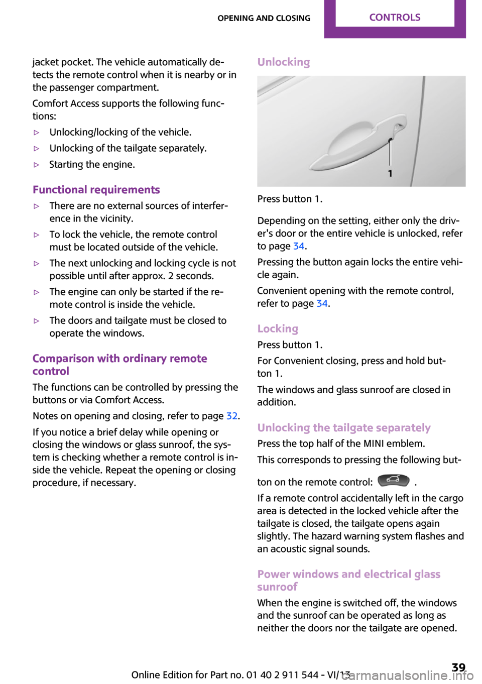
Unlocking
Press button 1.
Depending on the setting, either only the driv‐
er's door or the entire vehicle is unlocked, refer
to page 34.
Pressing the button again locks the entire vehi‐
cle again.
Convenient opening with the remote control,
refer to page 34.
Locking
Press button 1.
For Convenient closing, press and hold but‐
ton 1.
The windows and glass sunroof are closed in addition.
Unlocking the tailgate separately
Press the top half of the MINI emblem.
This corresponds to pressing the following but‐
ton on the remote control:
.
If a remote control accidentally left in the cargo
area is detected in the locked vehicle after the
tailgate is closed, the tailgate opens again
slightly. The hazard warning system flashes and
an acoustic signal sounds.
Power windows and electrical glass
sunroof
When the engine is switched off, the windows
and the sunroof can be operated as long as
neither the doors nor the tailgate are opened.
Seite 39Opening and closingControls39
Online Edition for Part no. 01 40 2 911 544 - VI/13
Page 80 of 282
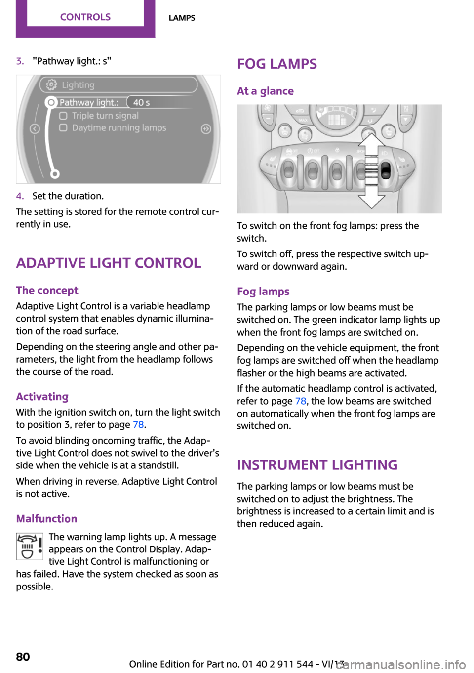
3."Pathway light.: s"4.Set the duration.
The setting is stored for the remote control cur‐
rently in use.
Adaptive Light Control
The concept
Adaptive Light Control is a variable headlamp
control system that enables dynamic illumina‐
tion of the road surface.
Depending on the steering angle and other pa‐
rameters, the light from the headlamp follows
the course of the road.
Activating
With the ignition switch on, turn the light switch
to position 3, refer to page 78.
To avoid blinding oncoming traffic, the Adap‐
tive Light Control does not swivel to the driver's
side when the vehicle is at a standstill.
When driving in reverse, Adaptive Light Control
is not active.
Malfunction The warning lamp lights up. A message
appears on the Control Display. Adap‐
tive Light Control is malfunctioning or
has failed. Have the system checked as soon as
possible.
Fog lamps
At a glance
To switch on the front fog lamps: press the
switch.
To switch off, press the respective switch up‐
ward or downward again.
Fog lamps
The parking lamps or low beams must be
switched on. The green indicator lamp lights up
when the front fog lamps are switched on.
Depending on the vehicle equipment, the front
fog lamps are switched off when the headlamp
flasher or the high beams are activated.
If the automatic headlamp control is activated,
refer to page 78, the low beams are switched
on automatically when the front fog lamps are
switched on.
Instrument lightingThe parking lamps or low beams must be
switched on to adjust the brightness. The
brightness is increased to a certain limit and is
then reduced again.
Seite 80ControlsLamps80
Online Edition for Part no. 01 40 2 911 544 - VI/13
Page 85 of 282
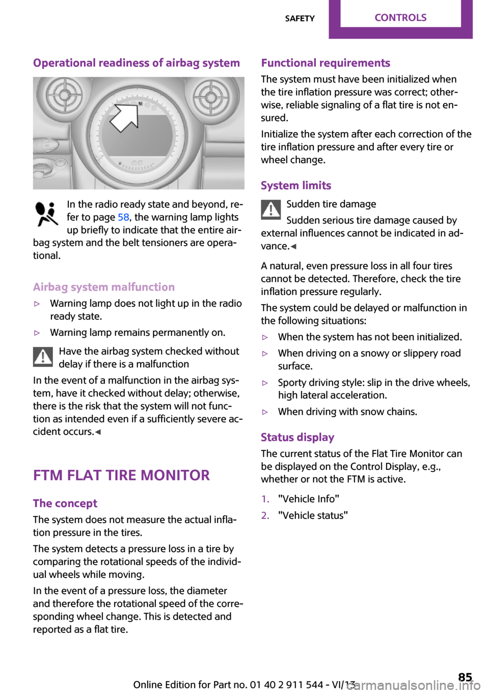
Operational readiness of airbag system
In the radio ready state and beyond, re‐
fer to page 58, the warning lamp lights
up briefly to indicate that the entire air‐
bag system and the belt tensioners are opera‐
tional.
Airbag system malfunction
▷Warning lamp does not light up in the radio
ready state.▷Warning lamp remains permanently on.
Have the airbag system checked without
delay if there is a malfunction
In the event of a malfunction in the airbag sys‐
tem, have it checked without delay; otherwise,
there is the risk that the system will not func‐
tion as intended even if a sufficiently severe ac‐
cident occurs. ◀
FTM Flat Tire Monitor The concept
The system does not measure the actual infla‐
tion pressure in the tires.
The system detects a pressure loss in a tire by
comparing the rotational speeds of the individ‐
ual wheels while moving.
In the event of a pressure loss, the diameter
and therefore the rotational speed of the corre‐
sponding wheel change. This is detected and
reported as a flat tire.
Functional requirements
The system must have been initialized when
the tire inflation pressure was correct; other‐
wise, reliable signaling of a flat tire is not en‐
sured.
Initialize the system after each correction of the
tire inflation pressure and after every tire or
wheel change.
System limits Sudden tire damage
Sudden serious tire damage caused by
external influences cannot be indicated in ad‐
vance. ◀
A natural, even pressure loss in all four tires
cannot be detected. Therefore, check the tire
inflation pressure regularly.
The system could be delayed or malfunction in
the following situations:▷When the system has not been initialized.▷When driving on a snowy or slippery road
surface.▷Sporty driving style: slip in the drive wheels,
high lateral acceleration.▷When driving with snow chains.
Status display
The current status of the Flat Tire Monitor can
be displayed on the Control Display, e.g.,
whether or not the FTM is active.
1."Vehicle Info"2."Vehicle status"Seite 85SafetyControls85
Online Edition for Part no. 01 40 2 911 544 - VI/13
Page 90 of 282
For a vehicle containing an average load, the
possible driving distance is ap‐
prox. 50 miles/80 km.
When the vehicle is driven with a damaged tire,
its handling characteristics change, e.g., re‐
duced lane stability during braking, a longer
braking distance, and altered self-steering
properties. Adjust your driving style accord‐
ingly. Avoid abrupt steering maneuvers or driv‐
ing over obstacles, e. g., curbs, potholes, etc.
Because the possible driving distance depends
on how the vehicle is used during the trip, the
actual distance may be smaller or greater de‐
pending on the driving speed, road conditions,
external temperature, cargo load, etc.
Continued driving with a flat tire
Drive moderately and do not exceed a
speed of 50 mph/80 km/h.
A loss of tire inflation pressure results in a
change in the handling characteristics, e.g., re‐
duced lane stability during braking, a longer
braking distance and altered self-steering prop‐
erties. ◀
Final tire failure
Vibrations or loud noises while driving
can indicate the final failure of the tire. Reduce
speed and stop; otherwise, pieces of the tire
could come loose and cause an accident. Do
not continue driving, and contact your service
center. ◀
Message when not reset The yellow warning lamp lights up. A
message is displayed on the onboard
monitor.
The system detected a wheel change but was
not yet reset. Warnings regarding the current
tire inflation pressure are not reliable.
Check the tire inflation pressure and reset the
system, refer to page 88.Malfunction
The small warning lamp flashes in yel‐
low and then lights up continuously; the
larger warning lamp comes on in yel‐
low.
On the onboard monitor, the tires are shown in
gray and a message appears.
No flat tire can be detected.
Display in the following situations:▷A wheel without TPM electronics is
mounted:
Have the system checked by the service
center if necessary.▷Malfunction:
Have the system checked.▷TPM could not be fully reset; reset the sys‐
tem again.
The small warning lamp flashes in yel‐
low and then lights up continuously; the
larger warning lamp comes on in yel‐
low.
On the onboard monitor, the tires are shown in
gray and a message appears.
No flat tire can be detected.
Display in the following situation:
▷Disturbance by other systems or devices
with the same radio frequency
After leaving the area of the disturbance,
the system automatically becomes active
again.
Declaration according to NHTSA/FMVSS
138 Tire Pressure Monitoring Systems
Each tire, including the spare (if provided)
should be checked monthly when cold and in‐
flated to the inflation pressure recommended
by the vehicle manufacturer on the vehicle
placard or tire inflation pressure label (If your
vehicle has tires of a different size than the size indicated on the vehicle placard or tire inflation
Seite 90ControlsSafety90
Online Edition for Part no. 01 40 2 911 544 - VI/13
Page 105 of 282
3.Hold the hand-held transmitter of the sys‐
tem to be operated a distance of approx. 1
to 3 in/2.5 to 8 cm away from the buttons
on the interior rearview mirror. The re‐
quired distance depends on the particular
hand-held transmitter.4.Press the button of the desired function on
the hand-held transmitter and the button
being programmed on the interior rearview
mirror simultaneously and hold. The LED on
the interior rearview mirror flashes slowly at
first.5.When the LED flashes more rapidly, release
both buttons. Rapid flashing indicates that
the button on the interior rearview mirror
has been programmed.
If the LED does not flash faster after 60 sec‐
onds, change the distance between the in‐
terior rearview mirror and the hand-held
transmitter and repeat the step. Multiple
trials at different distances may be neces‐
sary. Wait at least 15 seconds between tri‐
als.6.To program additional functions on other
buttons, repeat steps 3 to 5.
The systems can be operated with the buttons
on the interior rearview mirror.
Special characteristics of alternating-
code radio systems
If the system cannot be operated after re‐
peated programming, check whether the sys‐
tem to be operated uses an alternating-code
system.
Read the operating instructions of the system
or press and hold the programmed button on
the interior rearview mirror. If the LED on the
interior rearview mirror flashes rapidly at first
and then lights up continuously for 2 seconds,
the system is equipped with an alternating-
code system. This flashing LED pattern repeats
itself for approx. 20 seconds.
In systems with an alternating-code system, the
universal garage door opener and the system
must be additionally synchronized.
Please obtain additional information on syn‐
chronization in the operating instructions of the
system being set up.
The systems will be easier to synchronize with
the aid of a second person.
Synchronization:1.Park the vehicle within range of the re‐
mote-controlled system.2.Program the corresponding button on the
interior rearview mirror as described.3.Identify and press the synchronization but‐
ton on the system being set up. You have
approx. 30 seconds for the next step.4.Press and hold the button on the interior
rearview mirror for approx. 3 seconds and
then release it. Repeat this step up to three
times if necessary to complete the synchro‐
nization procedure. When synchronization
is completed, the programmed function is
executed.
Reprogramming individual buttons
1.Switch on the ignition.2.Hold the hand-held transmitter at a dis‐
tance of approx. 1 to 3 in/2.5 to 8 cm from
the memory buttons.
The required distance depends on the par‐
ticular hand-held transmitter.3.Press the memory button of the universal
garage door opener.4.If the LED flashes slowly after approx.
20 seconds, press the transmit button on
the hand-held transmitter.5.Release both buttons when the LED flashes
rapidly.
If the LED does not flash rapidly after ap‐
prox. 60 seconds, change the distance and
repeat the step.Seite 105Interior equipmentControls105
Online Edition for Part no. 01 40 2 911 544 - VI/13
Page 130 of 282
Saving fuelVehicle equipment
This chapter describes all series equipment as
well as country-specific and special equipment
offered for this model series.Therefore, it also
describes equipment that may not be found in
your vehicle, for instance due to the selected
special equipment or the country version. This
also applies to safety-related functions and sys‐
tems.
General information Your vehicle contains advanced technology for
the reduction of fuel consumption and emis‐
sions.
Fuel consumption depends on a number of dif‐
ferent factors. The implementation of certain
measures, driving style and regular mainte‐ nance can have an influence on fuel consump‐
tion and on the environmental impact.
Remove unnecessary cargo Additional weight increases fuel consumption.
Remove attached parts following use Remove unneeded auxiliary mirrors, roof or
rear luggage racks after use.
Attached parts on the vehicle impair the aero‐
dynamics and increase the fuel consumption.
Close both windows Open windows causes higher air resistance and
thus increases fuel consumption.
Check the tire inflation pressure
regularly
Check and, if necessary, correct the tire infla‐
tion pressure, refer to page 220, at least twice
a month and before starting on a long trip.Low tire inflation pressure increases rolling re‐
sistance and thus raises fuel consumption and
tire wear.
Drive away without delayDo not wait for the engine to warm-up while
the vehicle remains stationary. Start driving
right away, but at moderate engine speeds.
This is the fastest way for the cold engine to
reach its operating temperature.
Look well ahead when driving Avoid unnecessary acceleration and braking. To
achieve this, maintain a suitable distance to the
vehicle driving ahead of you.
Driving smoothly and looking ahead reduces
fuel consumption.
Avoid high engine speeds Use 1st gear to get the vehicle in motion. Be‐
ginning with 2nd gear, accelerate rapidly. When
accelerating, shift up before reaching high en‐
gine speeds.
When you reach the desired speed, shift into
the highest applicable gear and drive with the
engine speed as low as possible and at a con‐
stant speed.
As a rule: driving at low engine speeds lowers
fuel consumption and reduces wear.
Use coasting conditions
When approaching a red light, take your foot
off the accelerator and coast to a halt in the
highest applicable gear.
On a downhill slope, take your foot off the ac‐
celerator and coast in a suitable gear.
The flow of fuel is interrupted while coasting.Seite 130Driving tipsSaving fuel130
Online Edition for Part no. 01 40 2 911 544 - VI/13
Page 168 of 282

4.Open "Options".5."Random"
To switch off random playback: press the
MINI joystick.
Fast forward/reverse
Press and hold the button for the
corresponding direction.
Automatic repeat
The selected track, directories, or CDs are re‐
peated automatically.
Notes
CD player Do not remove the cover
The CD players are officially designated
Class 1 laser products. Do not operate if the
cover is damaged; otherwise, severe eye dam‐
age can result. ◀
CDs Using CDs
▷Do not use self-recorded CDs with la‐
bels applied, as these can become
detached during playback due to
heat buildup and can cause irrepara‐
ble damage to the device.▷Only use round CDs with a standard diame‐
ter of 4.7 in/12 cm and do not play CDs
with an adapter, e.g., single CDs; otherwise,
the CDs or the adapter may jam and no lon‐
ger eject. ◀
General malfunctions
▷The CD players have been optimized for
performance in vehicles. In some instances
they may be more sensitive to faulty CDs
than stationary devices would be.▷If a CD cannot be played, first check if it has
been inserted correctly.
Humidity
High levels of humidity can lead to condensa‐
tion on the CD or the laser's scan lens, and tem‐
porarily prevent playback.
Malfunctions with particular CDs If malfunctions occur only with particular CDs,
this can be due to one of the following causes:
Self-recorded CDs
▷Possible reasons for malfunctions with self-
recorded CDs are inconsistent data creation
or recording processes, or poor quality or
old age of the blank CD.▷Only label CDs on the upper side with a pen
intended for this purpose.
Damage
▷Avoid fingerprints, dust, scratches and
moisture.▷Store CDs in a sleeve.▷Do not subject CDs to temperatures over
50 ℃/122 ℉, high humidity, or direct sun‐
light.
CDs with copy protection
CDs are often provided with a copy protection
feature by the manufacturer. This can mean
Seite 168EntertainmentCD/multimedia168
Online Edition for Part no. 01 40 2 911 544 - VI/13
Page 189 of 282
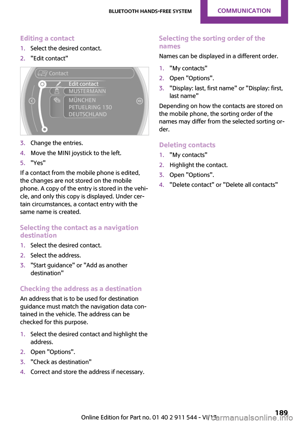
Editing a contact1.Select the desired contact.2."Edit contact"3.Change the entries.4.Move the MINI joystick to the left.5."Yes"
If a contact from the mobile phone is edited,
the changes are not stored on the mobile
phone. A copy of the entry is stored in the vehi‐
cle, and only this copy is displayed. Under cer‐
tain circumstances, a contact entry with the
same name is created.
Selecting the contact as a navigation
destination
1.Select the desired contact.2.Select the address.3."Start guidance" or "Add as another
destination"
Checking the address as a destination
An address that is to be used for destination
guidance must match the navigation data con‐
tained in the vehicle. The address can be
checked for this purpose.
1.Select the desired contact and highlight the
address.2.Open "Options".3."Check as destination"4.Correct and store the address if necessary.Selecting the sorting order of the
names
Names can be displayed in a different order.1."My contacts"2.Open "Options".3."Display: last, first name" or "Display: first,
last name"
Depending on how the contacts are stored on
the mobile phone, the sorting order of the
names may differ from the selected sorting or‐
der.
Deleting contacts
1."My contacts"2.Highlight the contact.3.Open "Options".4."Delete contact" or "Delete all contacts"Seite 189Bluetooth hands-free systemCommunication189
Online Edition for Part no. 01 40 2 911 544 - VI/13
Page 204 of 282
tained in the vehicle. The address can be
checked for this purpose.1.Select the desired contact and highlight the
address.2.Open "Options".3."Check as destination"4.Correct and store the address if necessary.
If the address is corrected and stored, a copy of
it is stored in the vehicle. The address is not
changed on the mobile phone.
New contact
General information
A contact can have up to 8 phone numbers,
2 addresses, 3 e-mail addresses and one Inter‐
net address.
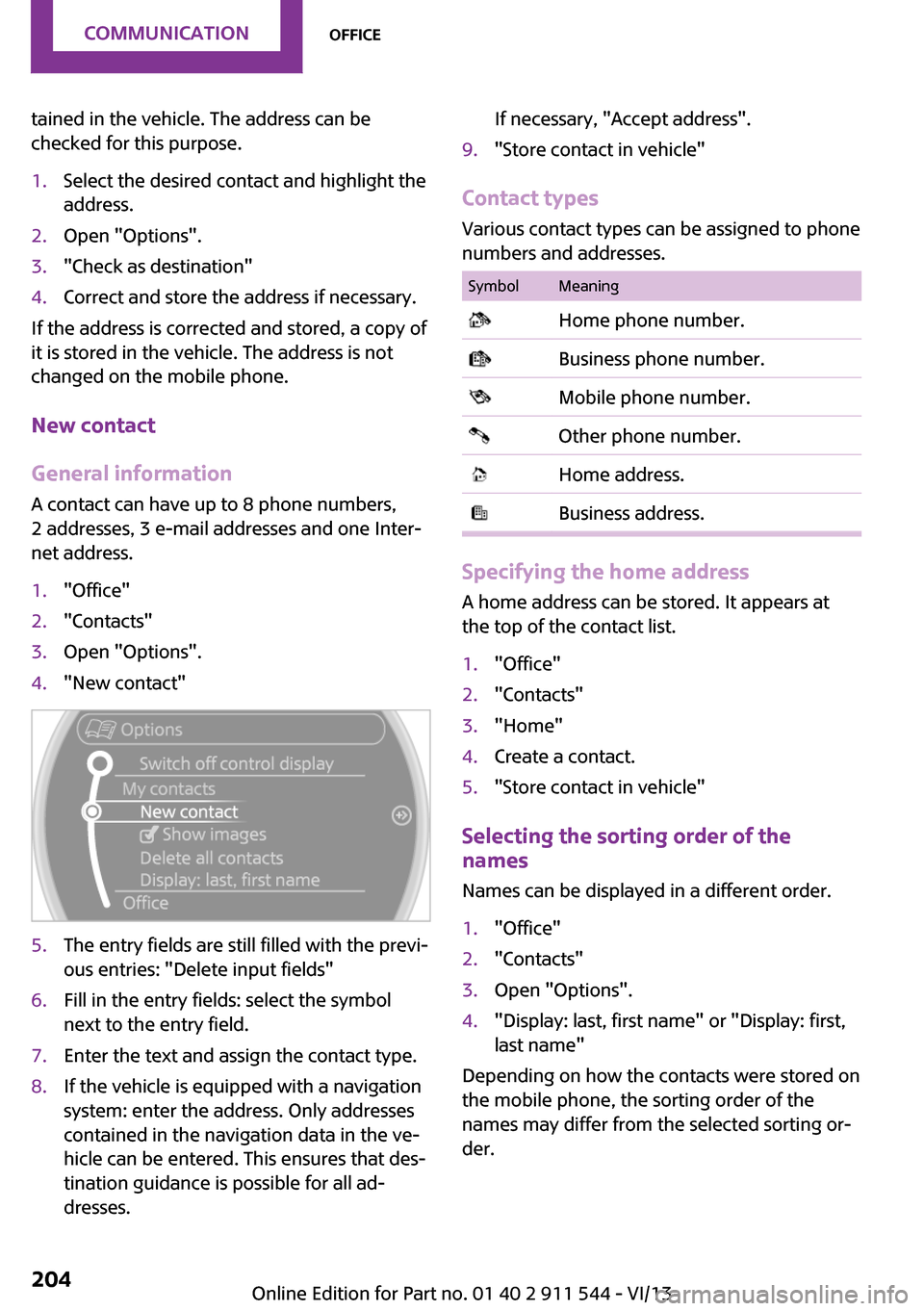
1."Office"2."Contacts"3.Open "Options".4."New contact"5.The entry fields are still filled with the previ‐
ous entries: "Delete input fields"6.Fill in the entry fields: select the symbol
next to the entry field.7.Enter the text and assign the contact type.8.If the vehicle is equipped with a navigation
system: enter the address. Only addresses
contained in the navigation data in the ve‐
hicle can be entered. This ensures that des‐
tination guidance is possible for all ad‐
dresses.If necessary, "Accept address".9."Store contact in vehicle"
Contact types
Various contact types can be assigned to phone
numbers and addresses.
SymbolMeaning Home phone number. Business phone number. Mobile phone number. Other phone number. Home address. Business address.
Specifying the home address
A home address can be stored. It appears at
the top of the contact list.
1."Office"2."Contacts"3."Home"4.Create a contact.5."Store contact in vehicle"
Selecting the sorting order of the
names
Names can be displayed in a different order.
1."Office"2."Contacts"3.Open "Options".4."Display: last, first name" or "Display: first,
last name"
Depending on how the contacts were stored on
the mobile phone, the sorting order of the
names may differ from the selected sorting or‐
der.
Seite 204CommunicationOffice204
Online Edition for Part no. 01 40 2 911 544 - VI/13
Page 228 of 282
Maximum speed of winter tires
If the maximum speed of the vehicle is higher
than the permissible speed for the winter tires,
then display a corresponding sign in the field of
vision. You can obtain this sign from the tire
specialist or from your service center.
Maximum speed for winter tires
Do not exceed the maximum speed for
the winter tires; otherwise, tire damage and ac‐
cidents can occur. ◀
Run-flat tires When mounting new tires or changing fromsummer to winter tires or vice versa, use run-
flat tires for your own safety. Also, a compact
wheel is not available in case of a flat tire. Your
service center will be glad to advise you.
Rotating wheels between axles
Different wear patterns occur on the front and
rear axles, depending on the individual condi‐
tions of use.
To ensure even wear on the tires, the wheels
can be rotated between the axles. Your service
center will be glad to advise you.
After changing the tires, check the tire inflation
pressure and correct it if necessary.
Storage Store wheels and tires in a cool, dry place with
as little exposure to light as possible.
Always protect tires against all contact with oil,
grease and fuels.
Do not exceed the maximum tire inflation pres‐
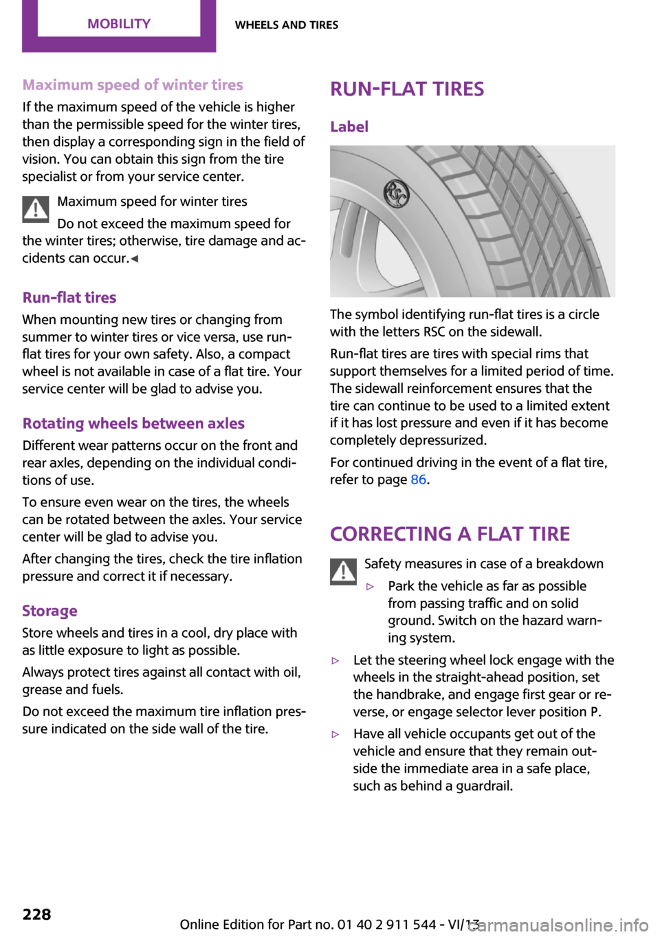
sure indicated on the side wall of the tire.Run-flat tires
Label
The symbol identifying run-flat tires is a circle
with the letters RSC on the sidewall.
Run-flat tires are tires with special rims that
support themselves for a limited period of time.
The sidewall reinforcement ensures that the
tire can continue to be used to a limited extent
if it has lost pressure and even if it has become
completely depressurized.
For continued driving in the event of a flat tire,
refer to page 86.
Correcting a flat tire Safety measures in case of a breakdown
▷Park the vehicle as far as possible
from passing traffic and on solid
ground. Switch on the hazard warn‐
ing system.▷Let the steering wheel lock engage with the
wheels in the straight-ahead position, set
the handbrake, and engage first gear or re‐
verse, or engage selector lever position P.▷Have all vehicle occupants get out of the
vehicle and ensure that they remain out‐
side the immediate area in a safe place,
such as behind a guardrail.Seite 228MobilityWheels and tires228
Online Edition for Part no. 01 40 2 911 544 - VI/13