check engine light MINI Countryman 2014 Owner's Manual (Mini Connected)
[x] Cancel search | Manufacturer: MINI, Model Year: 2014, Model line: Countryman, Model: MINI Countryman 2014Pages: 282, PDF Size: 6.76 MB
Page 17 of 282
Indicator/warning lamps
The concept
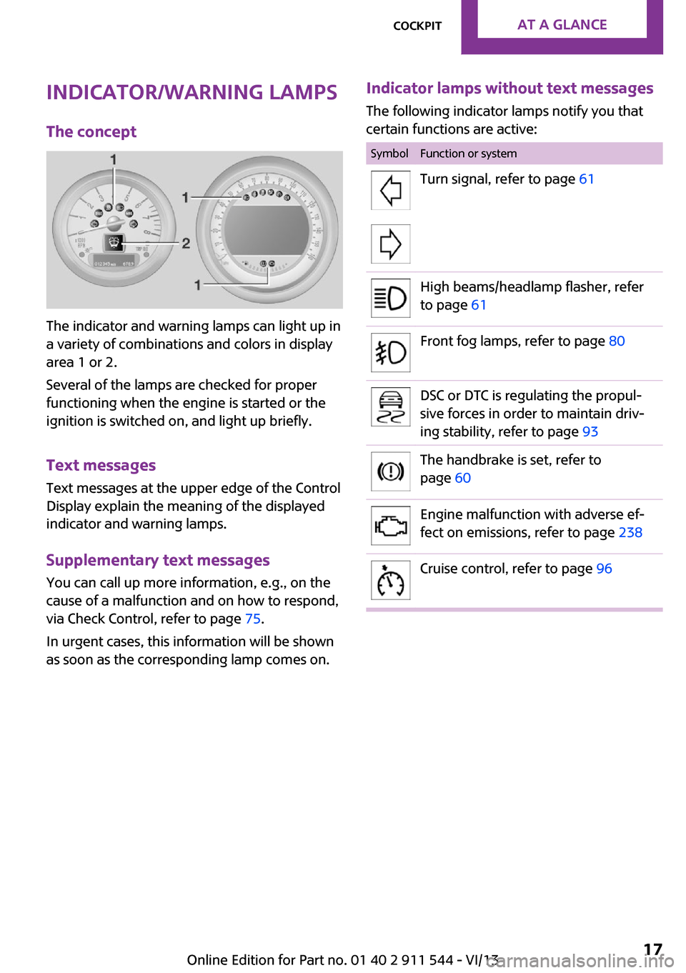
The indicator and warning lamps can light up in
a variety of combinations and colors in display
area 1 or 2.
Several of the lamps are checked for proper
functioning when the engine is started or the
ignition is switched on, and light up briefly.
Text messages
Text messages at the upper edge of the Control
Display explain the meaning of the displayed
indicator and warning lamps.
Supplementary text messages
You can call up more information, e.g., on the
cause of a malfunction and on how to respond,
via Check Control, refer to page 75.
In urgent cases, this information will be shown
as soon as the corresponding lamp comes on.
Indicator lamps without text messages
The following indicator lamps notify you that
certain functions are active:SymbolFunction or systemTurn signal, refer to page 61High beams/headlamp flasher, refer
to page 61Front fog lamps, refer to page 80DSC or DTC is regulating the propul‐
sive forces in order to maintain driv‐
ing stability, refer to page 93The handbrake is set, refer to
page 60Engine malfunction with adverse ef‐
fect on emissions, refer to page 238Cruise control, refer to page 96Seite 17CockpitAt a glance17
Online Edition for Part no. 01 40 2 911 544 - VI/13
Page 39 of 282
jacket pocket. The vehicle automatically de‐
tects the remote control when it is nearby or in
the passenger compartment.
Comfort Access supports the following func‐
tions:▷Unlocking/locking of the vehicle.▷Unlocking of the tailgate separately.▷Starting the engine.
Functional requirements
▷There are no external sources of interfer‐
ence in the vicinity.▷To lock the vehicle, the remote control
must be located outside of the vehicle.▷The next unlocking and locking cycle is not
possible until after approx. 2 seconds.▷The engine can only be started if the re‐
mote control is inside the vehicle.▷The doors and tailgate must be closed to
operate the windows.
Comparison with ordinary remote
control
The functions can be controlled by pressing the
buttons or via Comfort Access.
Notes on opening and closing, refer to page 32.
If you notice a brief delay while opening or
closing the windows or glass sunroof, the sys‐
tem is checking whether a remote control is in‐
side the vehicle. Repeat the opening or closing
procedure, if necessary.
Unlocking
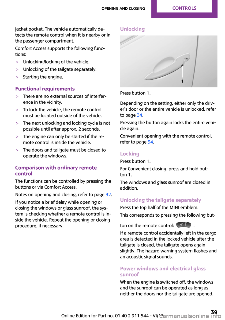
Press button 1.
Depending on the setting, either only the driv‐
er's door or the entire vehicle is unlocked, refer
to page 34.
Pressing the button again locks the entire vehi‐
cle again.
Convenient opening with the remote control,
refer to page 34.
Locking
Press button 1.
For Convenient closing, press and hold but‐
ton 1.
The windows and glass sunroof are closed in addition.
Unlocking the tailgate separately
Press the top half of the MINI emblem.
This corresponds to pressing the following but‐
ton on the remote control:
.
If a remote control accidentally left in the cargo
area is detected in the locked vehicle after the
tailgate is closed, the tailgate opens again
slightly. The hazard warning system flashes and
an acoustic signal sounds.
Power windows and electrical glass
sunroof
When the engine is switched off, the windows
and the sunroof can be operated as long as
neither the doors nor the tailgate are opened.
Seite 39Opening and closingControls39
Online Edition for Part no. 01 40 2 911 544 - VI/13
Page 40 of 282
When the door and tailgate are closed again
and the remote control is detected inside the
vehicle, the windows and the sunroof can be
operated again.
Insert the remote control into the ignition lock
to be able to operate the windows and the sun‐
roof while the engine is switched off and the
doors are open.
Switching on the radio ready state Press the Start/Stop button to switch on the
radio ready state, refer to page 58.
Do not depress the brake or the clutch; other‐
wise, the engine will start.
Starting the engine The engine can be started or the ignition can
be switched on, refer to page 58, when a re‐
mote control is inside the vehicle. It is not nec‐
essary to insert a remote control into the igni‐
tion lock.
Switching off the engine in cars with
automatic transmission
The engine can only be switched off with the
selector lever in position P, refer to page 65.
To switch off the engine with the selector lever
in position N, the remote control must be in‐
serted in the ignition lock.
Before driving a vehicle with automatic
transmission into a car wash1.Insert the remote control into the ignition
switch.2.Depress the brake pedal.3.Move the selector lever to position N.4.Switch the engine off.
The vehicle can roll.
Malfunction The Comfort Access functions can be disturbed
by local radio waves, such as by a mobile
phone in the immediate vicinity of the remote
control or when a mobile phone is being
charged in the vehicle.
If this occurs, open or close the vehicle using
the buttons on the remote control or use the
integrated key in the door lock.
To start the engine afterward, insert the remote
control into the ignition switch.
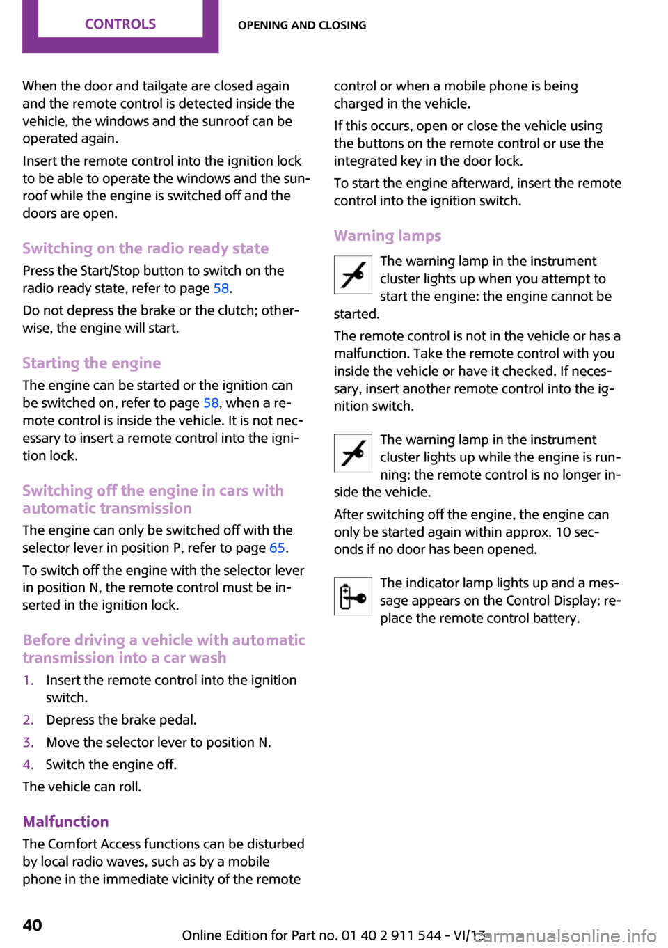
Warning lamps The warning lamp in the instrument
cluster lights up when you attempt to
start the engine: the engine cannot be
started.
The remote control is not in the vehicle or has a
malfunction. Take the remote control with you
inside the vehicle or have it checked. If neces‐
sary, insert another remote control into the ig‐
nition switch.
The warning lamp in the instrument
cluster lights up while the engine is run‐
ning: the remote control is no longer in‐
side the vehicle.
After switching off the engine, the engine can
only be started again within approx. 10 sec‐
onds if no door has been opened.
The indicator lamp lights up and a mes‐
sage appears on the Control Display: re‐
place the remote control battery.Seite 40ControlsOpening and closing40
Online Edition for Part no. 01 40 2 911 544 - VI/13
Page 75 of 282
Entering appointment dates
Enter the dates for the required inspections.
Make sure the date on the Control Display is set
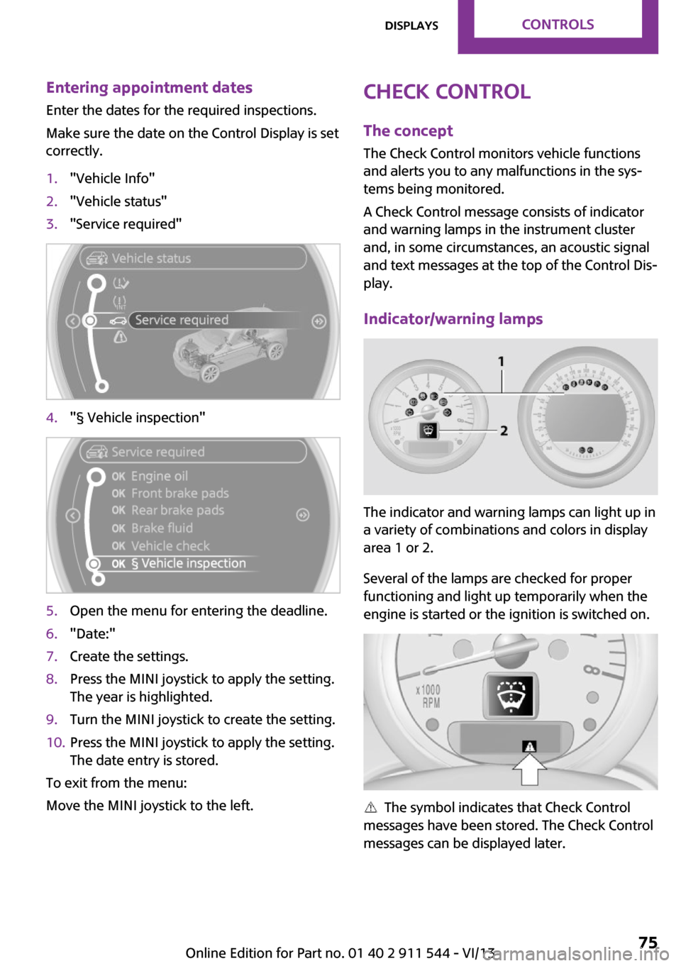
correctly.1."Vehicle Info"2."Vehicle status"3."Service required"4."§ Vehicle inspection"5.Open the menu for entering the deadline.6."Date:"7.Create the settings.8.Press the MINI joystick to apply the setting.
The year is highlighted.9.Turn the MINI joystick to create the setting.10.Press the MINI joystick to apply the setting.
The date entry is stored.
To exit from the menu:
Move the MINI joystick to the left.
Check Control
The concept
The Check Control monitors vehicle functions
and alerts you to any malfunctions in the sys‐
tems being monitored.
A Check Control message consists of indicator
and warning lamps in the instrument cluster
and, in some circumstances, an acoustic signal
and text messages at the top of the Control Dis‐
play.
Indicator/warning lamps
The indicator and warning lamps can light up in
a variety of combinations and colors in display
area 1 or 2.
Several of the lamps are checked for proper
functioning and light up temporarily when the
engine is started or the ignition is switched on.
The symbol indicates that Check Control
messages have been stored. The Check Control
messages can be displayed later.
Seite 75DisplaysControls75
Online Edition for Part no. 01 40 2 911 544 - VI/13
Page 98 of 282
▷By the rear middle sensors at approx.
5 ft/1.50 m.
Avoid driving quickly with PDC
PDC is a parking aid that can display ob‐
jects when the vehicle approaches them slowly,
as is the case during parking maneuvers. Avoid
driving toward an object quickly as the system
may then be too late in issuing a warning for
technical reasons. ◀
Automatic operation
The system is activated after approx. one sec‐ ond when reverse gear or selector lever posi‐
tion R is engaged while the engine is running or
the ignition is switched on. Await this short pe‐
riod before setting the vehicle into motion.
Signal tones
The closer the vehicle is to the object, the
shorter the intervals become. If the distance to
a detected object is less than approx.
12 in/30 cm, a continuous tone is sounded.
If the distance remains constant, for example
when driving parallel to a wall, the signal tone
is stopped after approx. 3 seconds.
PDC with visual warning
Displaying the approach to an object on the
Control Display. The contours of distant objects
are displayed on the Control Display before a
signal tone is output. The display is shown on
the Control Display as soon as reverse gear or
selector lever position R is engaged.
System limits Check the traffic situation as well
PDC cannot serve as a substitute for the
driver's personal judgment of the traffic situa‐
tion. Check the traffic situation around the ve‐
hicle with your own eyes. Otherwise, an acci‐
dent could result from road users or objects
located outside of the PDC detection range.
Loud noises from outside and inside the vehicle
may prevent you from hearing the PDC's signal
tone. ◀
Malfunction The warning lamp lights up. A message
appears on the Control Display. PDC is
malfunctioning or has failed. Have the
system checked.
To ensure full functionality of the sensors, keep
the sensors clean and free of ice. When using
high-pressure washers, do not spray the sen‐
sors for long periods and maintain a distance of
at least 12 in/30 cm.Seite 98ControlsDriving comfort98
Online Edition for Part no. 01 40 2 911 544 - VI/13
Page 130 of 282
Saving fuelVehicle equipment
This chapter describes all series equipment as
well as country-specific and special equipment
offered for this model series.Therefore, it also
describes equipment that may not be found in
your vehicle, for instance due to the selected
special equipment or the country version. This
also applies to safety-related functions and sys‐
tems.
General information Your vehicle contains advanced technology for
the reduction of fuel consumption and emis‐
sions.
Fuel consumption depends on a number of dif‐
ferent factors. The implementation of certain
measures, driving style and regular mainte‐ nance can have an influence on fuel consump‐
tion and on the environmental impact.
Remove unnecessary cargo Additional weight increases fuel consumption.
Remove attached parts following use Remove unneeded auxiliary mirrors, roof or
rear luggage racks after use.
Attached parts on the vehicle impair the aero‐
dynamics and increase the fuel consumption.
Close both windows Open windows causes higher air resistance and
thus increases fuel consumption.
Check the tire inflation pressure
regularly
Check and, if necessary, correct the tire infla‐
tion pressure, refer to page 220, at least twice
a month and before starting on a long trip.Low tire inflation pressure increases rolling re‐
sistance and thus raises fuel consumption and
tire wear.
Drive away without delayDo not wait for the engine to warm-up while
the vehicle remains stationary. Start driving
right away, but at moderate engine speeds.
This is the fastest way for the cold engine to
reach its operating temperature.
Look well ahead when driving Avoid unnecessary acceleration and braking. To
achieve this, maintain a suitable distance to the
vehicle driving ahead of you.
Driving smoothly and looking ahead reduces
fuel consumption.
Avoid high engine speeds Use 1st gear to get the vehicle in motion. Be‐
ginning with 2nd gear, accelerate rapidly. When
accelerating, shift up before reaching high en‐
gine speeds.
When you reach the desired speed, shift into
the highest applicable gear and drive with the
engine speed as low as possible and at a con‐
stant speed.
As a rule: driving at low engine speeds lowers
fuel consumption and reduces wear.
Use coasting conditions
When approaching a red light, take your foot
off the accelerator and coast to a halt in the
highest applicable gear.
On a downhill slope, take your foot off the ac‐
celerator and coast in a suitable gear.
The flow of fuel is interrupted while coasting.Seite 130Driving tipsSaving fuel130
Online Edition for Part no. 01 40 2 911 544 - VI/13
Page 230 of 282
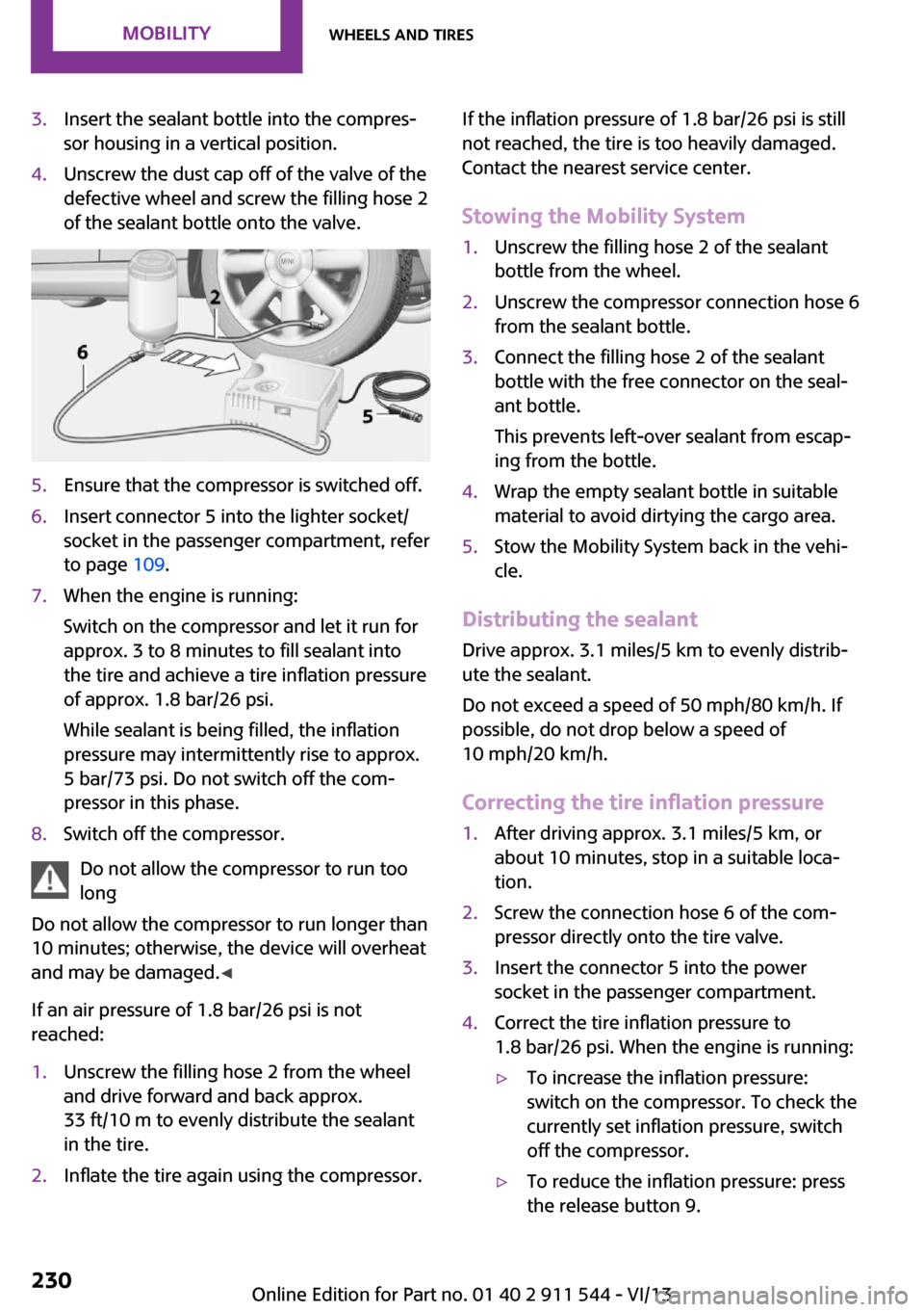
3.Insert the sealant bottle into the compres‐
sor housing in a vertical position.4.Unscrew the dust cap off of the valve of the
defective wheel and screw the filling hose 2
of the sealant bottle onto the valve.5.Ensure that the compressor is switched off.6.Insert connector 5 into the lighter socket/
socket in the passenger compartment, refer
to page 109.7.When the engine is running:
Switch on the compressor and let it run for
approx. 3 to 8 minutes to fill sealant into
the tire and achieve a tire inflation pressure
of approx. 1.8 bar/26 psi.
While sealant is being filled, the inflation
pressure may intermittently rise to approx.
5 bar/73 psi. Do not switch off the com‐
pressor in this phase.8.Switch off the compressor.
Do not allow the compressor to run too
long
Do not allow the compressor to run longer than
10 minutes; otherwise, the device will overheat
and may be damaged. ◀
If an air pressure of 1.8 bar/26 psi is not
reached:
1.Unscrew the filling hose 2 from the wheel
and drive forward and back approx.
33 ft/10 m to evenly distribute the sealant
in the tire.2.Inflate the tire again using the compressor.If the inflation pressure of 1.8 bar/26 psi is still
not reached, the tire is too heavily damaged.
Contact the nearest service center.
Stowing the Mobility System1.Unscrew the filling hose 2 of the sealant
bottle from the wheel.2.Unscrew the compressor connection hose 6
from the sealant bottle.3.Connect the filling hose 2 of the sealant
bottle with the free connector on the seal‐
ant bottle.
This prevents left-over sealant from escap‐
ing from the bottle.4.Wrap the empty sealant bottle in suitable
material to avoid dirtying the cargo area.5.Stow the Mobility System back in the vehi‐
cle.
Distributing the sealant
Drive approx. 3.1 miles/5 km to evenly distrib‐
ute the sealant.
Do not exceed a speed of 50 mph/80 km/h. If
possible, do not drop below a speed of
10 mph/20 km/h.
Correcting the tire inflation pressure
1.After driving approx. 3.1 miles/5 km, or
about 10 minutes, stop in a suitable loca‐
tion.2.Screw the connection hose 6 of the com‐
pressor directly onto the tire valve.3.Insert the connector 5 into the power
socket in the passenger compartment.4.Correct the tire inflation pressure to
1.8 bar/26 psi. When the engine is running:▷To increase the inflation pressure:
switch on the compressor. To check the
currently set inflation pressure, switch
off the compressor.▷To reduce the inflation pressure: press
the release button 9.Seite 230MobilityWheels and tires230
Online Edition for Part no. 01 40 2 911 544 - VI/13
Page 236 of 282
CoolantVehicle equipment
This chapter describes all series equipment as
well as country-specific and special equipment
offered for this model series.Therefore, it also
describes equipment that may not be found in
your vehicle, for instance due to the selected
special equipment or the country version. This
also applies to safety-related functions and sys‐
tems.
General information Danger of burns from hot engine
Do not open the cooling system while the
engine is hot; otherwise, escaping coolant may
cause burns. ◀
Suitable additives
Only use suitable additives; otherwise,
engine damage may occur. The additives are
harmful to your health. ◀
Coolant consists of water and additives.
Not all commercially available additives are
suitable for your MINI vehicle. Ask your service
center for suitable additives.
Coolant temperature
If the coolant and therefore the engine over‐
heat, a warning lamp lights up. A message ap‐
pears on the Control Display.
Coolant level Checking1.Do not open the hood until the engine has
cooled down.2.Turn the expansion tank cap counterclock‐
wise slightly to allow any accumulated
pressure to escape; then continue turning
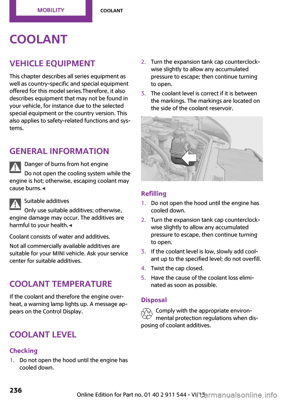
to open.3.The coolant level is correct if it is between
the markings. The markings are located on
the side of the coolant reservoir.
Refilling
1.Do not open the hood until the engine has
cooled down.2.Turn the expansion tank cap counterclock‐
wise slightly to allow any accumulated
pressure to escape, then continue turning
to open.3.If the coolant level is low, slowly add cool‐
ant up to the specified level; do not overfill.4.Twist the cap closed.5.Have the cause of the coolant loss elimi‐
nated as soon as possible.
Disposal
Comply with the appropriate environ‐mental protection regulations when dis‐
posing of coolant additives.
Seite 236MobilityCoolant236
Online Edition for Part no. 01 40 2 911 544 - VI/13
Page 238 of 282
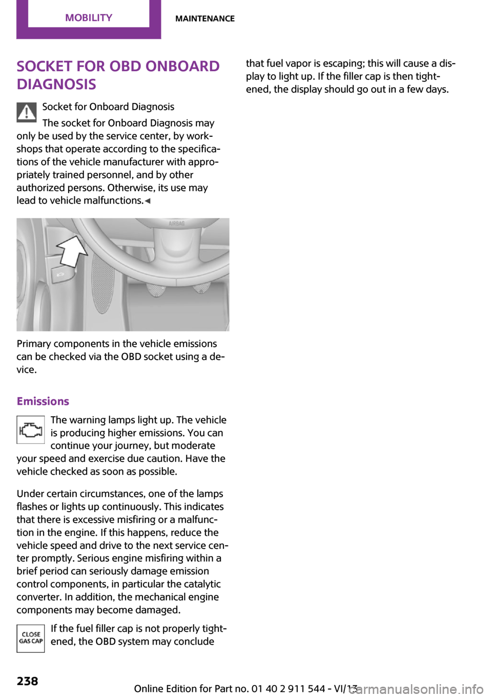
Socket for OBD Onboard
Diagnosis
Socket for Onboard Diagnosis
The socket for Onboard Diagnosis may
only be used by the service center, by work‐
shops that operate according to the specifica‐
tions of the vehicle manufacturer with appro‐
priately trained personnel, and by other
authorized persons. Otherwise, its use may
lead to vehicle malfunctions. ◀
Primary components in the vehicle emissions
can be checked via the OBD socket using a de‐
vice.
Emissions The warning lamps light up. The vehicle
is producing higher emissions. You can
continue your journey, but moderate
your speed and exercise due caution. Have the
vehicle checked as soon as possible.
Under certain circumstances, one of the lamps
flashes or lights up continuously. This indicates
that there is excessive misfiring or a malfunc‐
tion in the engine. If this happens, reduce the
vehicle speed and drive to the next service cen‐
ter promptly. Serious engine misfiring within a
brief period can seriously damage emission
control components, in particular the catalytic
converter. In addition, the mechanical engine
components may become damaged.
If the fuel filler cap is not properly tight‐
ened, the OBD system may conclude
that fuel vapor is escaping; this will cause a dis‐
play to light up. If the filler cap is then tight‐
ened, the display should go out in a few days.Seite 238MobilityMaintenance238
Online Edition for Part no. 01 40 2 911 544 - VI/13
Page 246 of 282
Vehicle batteryMaintenance
The battery is maintenance-free, i.e., the elec‐
trolyte will last for the life of the battery in tem‐
perate climate conditions.
The service center will be happy to answer any
questions on the battery.
Battery replacement Use approved vehicle batteries
Only use vehicle batteries that have been
approved for your vehicle by the manufacturer;
otherwise, the vehicle could be damaged and
systems or functions may not be fully availa‐
ble. ◀
Have the vehicle battery registered by the serv‐
ice center after it is replaced to ensure that all
comfort functions are available without restric‐
tions and that any associated Check Control
messages are no longer displayed.
Charging the battery
Note Do not connect the charger to the socket
Do not connect the battery charger to the
socket installed in the vehicle at the factory as
this could damage the battery. ◀
Only charge the battery in the vehicle when the engine is switched off. Connections, refer to
page 248.
General information Ensure that the battery is sufficiently charged to
achieve the full battery life.
It may be necessary to charge the battery in
the following cases:▷When the vehicle is frequently used to
travel short distances.▷When the vehicle has not been driven for
more than one month.Power failure
After a temporary power failure, some equip‐
ment will be restricted in its use and will need
to be reinitialized. In addition, certain individual
settings will be lost and must be updated:▷Time and date: the values must be up‐
dated, refer to page 72.▷Radio: the stations need to be stored again,
refer to page 159.▷Onboard monitor: full functionality will be
restored after some time.▷Glass sunroof, electrical: it may only be pos‐
sible to tilt the roof. The system needs to be
initialized. Contact the service center.
Indicator/warning lamps
Lights up red: the vehicle battery is no
longer being charged. Alternator mal‐
function.
Switch off all unnecessary electrical consumers.
Have the battery checked immediately.
Lights up yellow: the battery charge
level is very low, the battery is old, or it
is not securely connected.
Charge the battery by taking a long drive or us‐
ing an external charger. If the indicators appear
again, have the battery checked as soon as
possible.
Disposing of old batteries Have used batteries disposed of by the
service center after they are replaced or
take them to a recycling center.
Maintain the battery in an upright position for
transport and storage. Secure the battery so
that it does not tip over during transport.
Seite 246MobilityReplacing components246
Online Edition for Part no. 01 40 2 911 544 - VI/13