cargo MINI Countryman 2014 Owner's Manual
[x] Cancel search | Manufacturer: MINI, Model Year: 2014, Model line: Countryman, Model: MINI Countryman 2014Pages: 218, PDF Size: 5.45 MB
Page 29 of 218
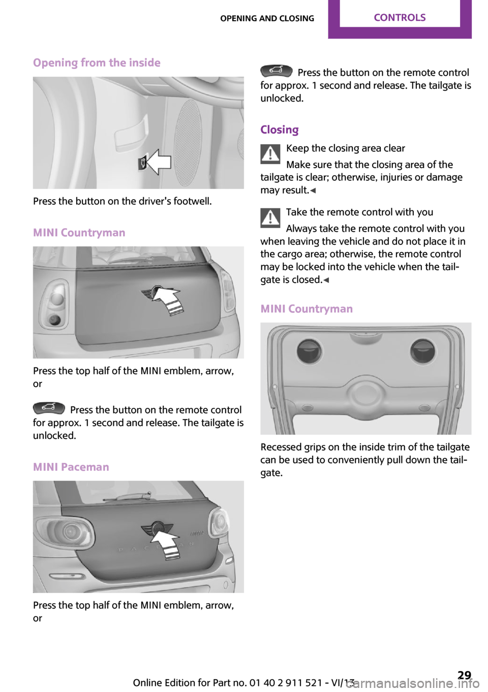
Opening from the inside
Press the button on the driver's footwell.
MINI Countryman
Press the top half of the MINI emblem, arrow,
or
Press the button on the remote control
for approx. 1 second and release. The tailgate is
unlocked.
MINI Paceman
Press the top half of the MINI emblem, arrow,
or
Press the button on the remote control
for approx. 1 second and release. The tailgate is
unlocked.
Closing Keep the closing area clear
Make sure that the closing area of the
tailgate is clear; otherwise, injuries or damage
may result. ◀
Take the remote control with you
Always take the remote control with you
when leaving the vehicle and do not place it in
the cargo area; otherwise, the remote control
may be locked into the vehicle when the tail‐
gate is closed. ◀
MINI Countryman
Recessed grips on the inside trim of the tailgate
can be used to conveniently pull down the tail‐
gate.
Seite 29Opening and closingControls29
Online Edition for Part no. 01 40 2 911 521 - VI/13
Page 31 of 218
If a remote control accidentally left in the cargo
area is detected in the locked vehicle after the
tailgate is closed, the tailgate opens again
slightly. The hazard warning system flashes and
an acoustic signal sounds.
Power windows and electrical glass
sunroof
When the engine is switched off, the windows
and the sunroof can be operated as long as
neither the doors nor the tailgate are opened.
When the door and tailgate are closed again
and the remote control is detected inside the
vehicle, the windows and the sunroof can be
operated again.
Insert the remote control into the ignition lock
to be able to operate the windows and the sun‐
roof while the engine is switched off and the
doors are open.
Switching on the radio ready state Press the Start/Stop button to switch on the
radio ready state, refer to page 49.
Do not depress the brake or the clutch; other‐
wise, the engine will start.
Starting the engine The engine can be started or the ignition can
be switched on, refer to page 49, when a re‐
mote control is inside the vehicle. It is not nec‐
essary to insert a remote control into the igni‐
tion lock.
Switching off the engine in cars with
automatic transmission
The engine can only be switched off with the
selector lever in position P, refer to page 56.
To switch off the engine with the selector lever
in position N, the remote control must be in‐
serted in the ignition lock.Before driving a vehicle with automatic
transmission into a car wash1.Insert the remote control into the ignition
switch.2.Depress the brake pedal.3.Move the selector lever to position N.4.Switch the engine off.
The vehicle can roll.
Malfunction The Comfort Access functions can be disturbed
by local radio waves, such as by a mobile
phone in the immediate vicinity of the remote
control or when a mobile phone is being
charged in the vehicle.
If this occurs, open or close the vehicle using
the buttons on the remote control or use the
integrated key in the door lock.
To start the engine afterward, insert the remote
control into the ignition switch.
Warning lamps The warning lamp in the instrument
cluster lights up when you attempt to
start the engine: the engine cannot be
started.
The remote control is not in the vehicle or has a
malfunction. Take the remote control with you
inside the vehicle or have it checked. If neces‐
sary, insert another remote control into the ig‐
nition switch.
The warning lamp in the instrument
cluster lights up while the engine is run‐
ning: the remote control is no longer in‐
side the vehicle.
After switching off the engine, the engine can
only be started again within approx. 10 sec‐
onds if no door has been opened.
The indicator lamp lights up: replace
the remote control battery.
Seite 31Opening and closingControls31
Online Edition for Part no. 01 40 2 911 521 - VI/13
Page 39 of 218
The shoulder strap's anchorage point will be
correct for adult seat occupants of every build if
the seat is correctly adjusted.
One person per safety belt
Never allow more than one person to
wear a single safety belt. Never allow infants or
small children to ride on a passenger's lap. ◀
Putting on the belt
Lay the belt, without twisting, snugly
across the lap and shoulders, as close to the
body as possible. Make sure that the belt lies
low around the hips in the lap area and does
not press on the abdomen. Otherwise, the belt
can slip over the hips in the lap area in a frontal
impact and injure the abdomen.
The safety belt must not lie across the neck, rub
on sharp edges, be routed over solid or breaka‐
ble objects, or be pinched. ◀
Reduction of restraining effect
Avoid wearing clothing that prevents the
belt from fitting properly, and pull the shoulder
belt periodically to readjust the tension across
your lap; otherwise, the retention effect of the
safety belt may be reduced. ◀
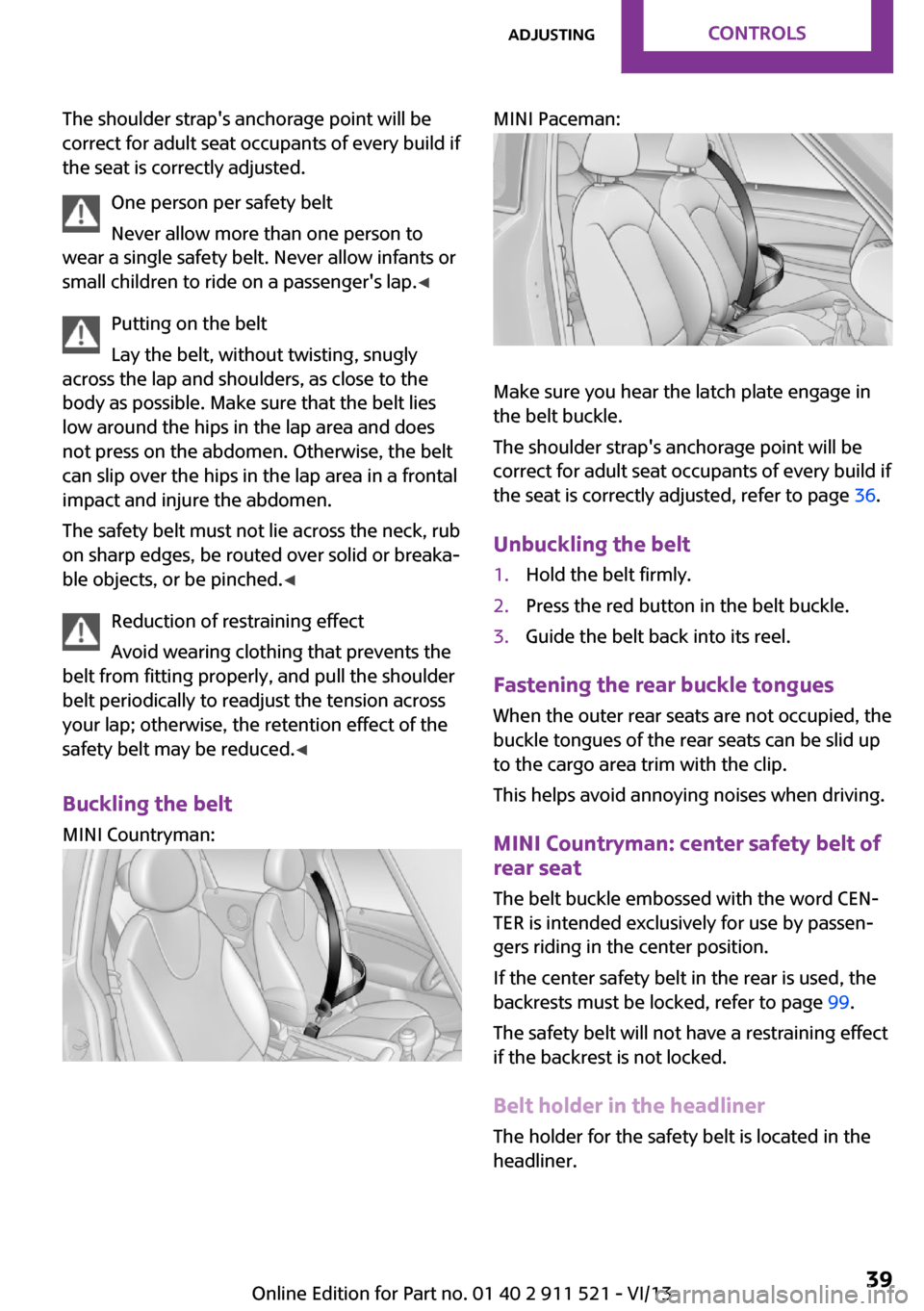
Buckling the belt MINI Countryman:
MINI Paceman:
Make sure you hear the latch plate engage in
the belt buckle.
The shoulder strap's anchorage point will be
correct for adult seat occupants of every build if
the seat is correctly adjusted, refer to page 36.
Unbuckling the belt
1.Hold the belt firmly.2.Press the red button in the belt buckle.3.Guide the belt back into its reel.
Fastening the rear buckle tongues When the outer rear seats are not occupied, thebuckle tongues of the rear seats can be slid up
to the cargo area trim with the clip.
This helps avoid annoying noises when driving.
MINI Countryman: center safety belt of
rear seat
The belt buckle embossed with the word CEN‐
TER is intended exclusively for use by passen‐
gers riding in the center position.
If the center safety belt in the rear is used, the
backrests must be locked, refer to page 99.
The safety belt will not have a restraining effect
if the backrest is not locked.
Belt holder in the headliner The holder for the safety belt is located in the
headliner.
Seite 39AdjustingControls39
Online Edition for Part no. 01 40 2 911 521 - VI/13
Page 47 of 218
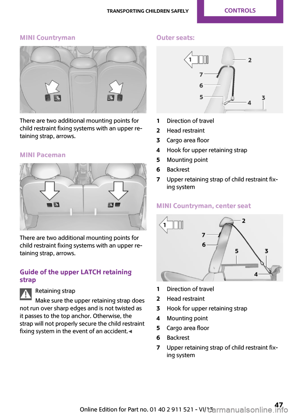
MINI Countryman
There are two additional mounting points for
child restraint fixing systems with an upper re‐
taining strap, arrows.
MINI Paceman
There are two additional mounting points for
child restraint fixing systems with an upper re‐
taining strap, arrows.
Guide of the upper LATCH retaining
strap
Retaining strap
Make sure the upper retaining strap does
not run over sharp edges and is not twisted as
it passes to the top anchor. Otherwise, the
strap will not properly secure the child restraint
fixing system in the event of an accident. ◀
Outer seats:1Direction of travel2Head restraint3Cargo area floor4Hook for upper retaining strap5Mounting point6Backrest7Upper retaining strap of child restraint fix‐
ing system
MINI Countryman, center seat
1Direction of travel2Head restraint3Hook for upper retaining strap4Mounting point5Cargo area floor6Backrest7Upper retaining strap of child restraint fix‐
ing systemSeite 47Transporting children safelyControls47
Online Edition for Part no. 01 40 2 911 521 - VI/13
Page 48 of 218
Attaching the upper retaining strap to
the mounting point1.Slide the head restraint upward.2.Center seat: fold the cargo area floor for‐
ward.3.Guide the upper retaining strap between
the supports of the head restraint.4.Attach the upper retaining strap to the
mounting point with the hook.5.Slide the head restraint into the bottom po‐
sition.6.Pull the upper retaining strap taut.
MINI Countryman: lock‐
ing doors and windows
Rear doors
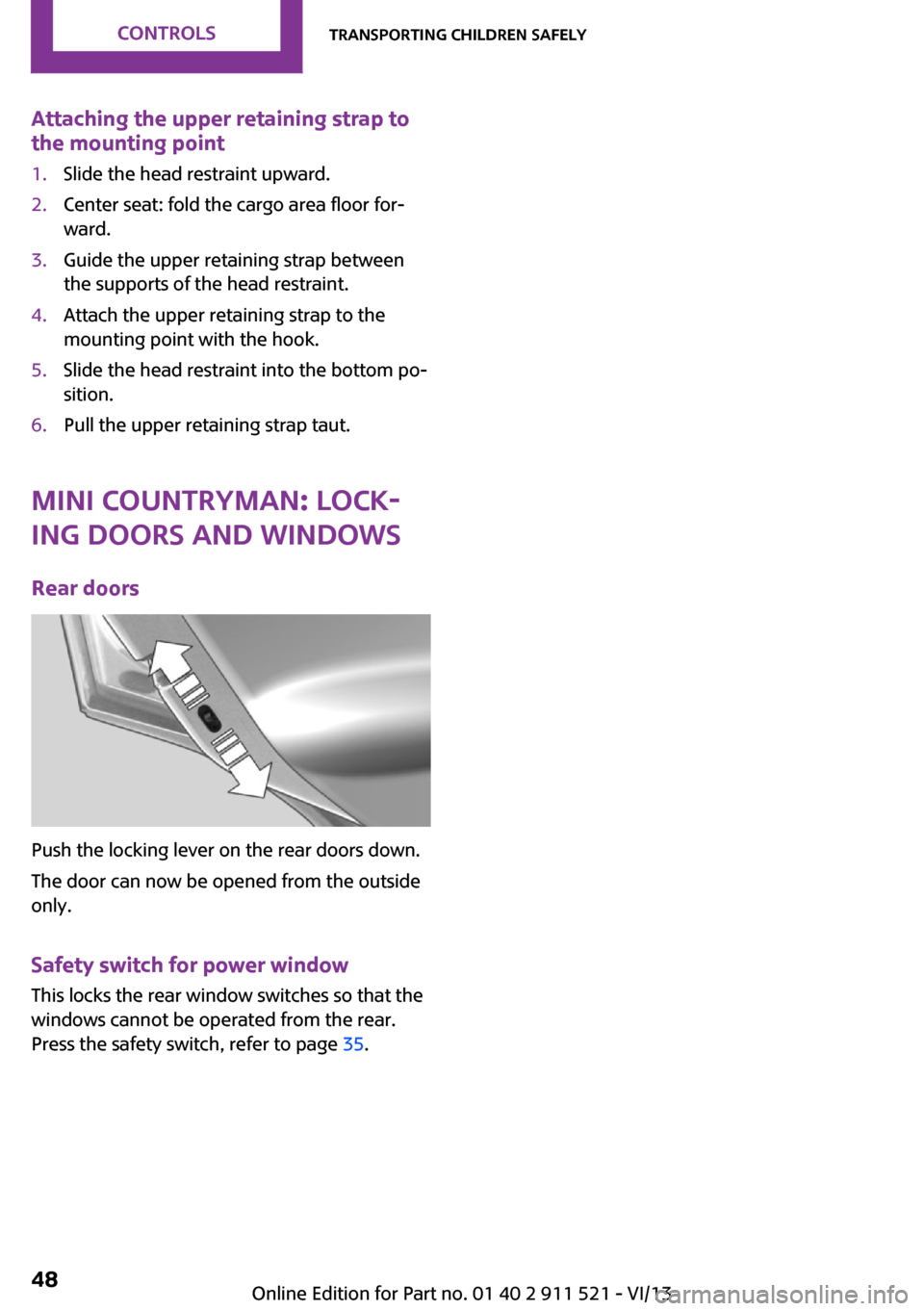
Push the locking lever on the rear doors down.
The door can now be opened from the outside
only.
Safety switch for power window This locks the rear window switches so that the
windows cannot be operated from the rear.
Press the safety switch, refer to page 35.
Seite 48ControlsTransporting children safely48
Online Edition for Part no. 01 40 2 911 521 - VI/13
Page 70 of 218
Depending on the steering angle and other pa‐
rameters, the light from the headlamp follows
the course of the road.
Activating With the ignition switch on, turn the light switch
to position 3, refer to page 67.
To avoid blinding oncoming traffic, the Adap‐
tive Light Control does not swivel to the driver's
side when the vehicle is at a standstill.
When driving in reverse, Adaptive Light Control
is not active.
Malfunction The warning lamp lights up. Adaptive
Light Control is malfunctioning or has
failed. Have the system checked as
soon as possible.
More information, refer to page 190.
Fog lamps
At a glance
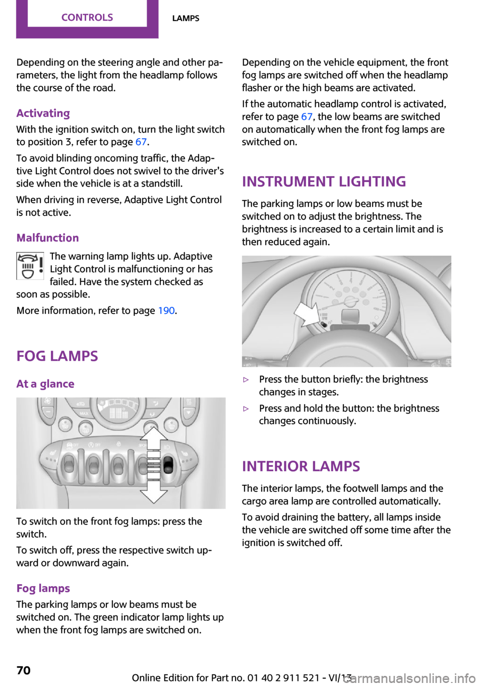
To switch on the front fog lamps: press the
switch.
To switch off, press the respective switch up‐
ward or downward again.
Fog lamps
The parking lamps or low beams must be
switched on. The green indicator lamp lights up
when the front fog lamps are switched on.
Depending on the vehicle equipment, the front
fog lamps are switched off when the headlamp
flasher or the high beams are activated.
If the automatic headlamp control is activated,
refer to page 67, the low beams are switched
on automatically when the front fog lamps are
switched on.
Instrument lighting
The parking lamps or low beams must be
switched on to adjust the brightness. The
brightness is increased to a certain limit and is then reduced again.▷Press the button briefly: the brightness
changes in stages.▷Press and hold the button: the brightness
changes continuously.
Interior lamps
The interior lamps, the footwell lamps and the
cargo area lamp are controlled automatically.
To avoid draining the battery, all lamps inside
the vehicle are switched off some time after the
ignition is switched off.
Seite 70ControlsLamps70
Online Edition for Part no. 01 40 2 911 521 - VI/13
Page 77 of 218
Continued driving with a flat tire
If continuing to drive with a damaged tire:1.Avoid sudden braking and steering maneu‐
vers.2.Do not exceed a speed of 50 mph/80 km/h.3.At the next opportunity, check the inflation
pressure in all four tires.
If the tire inflation pressure in all four tires is
correct, the Flat Tire Monitor may not have
been initialized. In this case, initialize the
system.
Possible driving distance with complete loss of
tire inflation pressure:
The possible driving distance after a loss of tire
inflation pressure depends on the cargo load
and the driving style and conditions.
For a vehicle containing an average load, the
possible driving distance is ap‐
prox. 50 miles/80 km.
When the vehicle is driven with a damaged tire,
its handling characteristics change, e.g., re‐
duced lane stability during braking, a longer
braking distance, and altered self-steering
properties. Adjust your driving style accord‐
ingly. Avoid abrupt steering maneuvers or driv‐
ing over obstacles, e. g., curbs, potholes, etc.
Because the possible driving distance depends
on how the vehicle is used during the trip, the
actual distance may be smaller or greater de‐
pending on the driving speed, road conditions,
external temperature, cargo load, etc.
Continued driving with a flat tire
Drive moderately and do not exceed a
speed of 50 mph/80 km/h.
A loss of tire inflation pressure results in a
change in the handling characteristics, e.g., re‐
duced lane stability during braking, a longer
braking distance and altered self-steering prop‐
erties. ◀
Final tire failure
Vibrations or loud noises while driving
can indicate the final failure of the tire. Reduce
speed and stop; otherwise, pieces of the tire
could come loose and cause an accident. Do
not continue driving, and contact your service
center. ◀
Tire Pressure Monitor
TPM
The concept
The tire inflation pressure is measured in the
four mounted tires. The system notifies you if
there is a significant loss of pressure in one or
more tires.
Functional requirements The system must have been reset while the in‐
flation pressure was correct; otherwise, reliable
signaling of a flat tire is not ensured.
Always use wheels with TPM electronics to en‐
sure that the system will operate properly.
Reset the system after each correction of the
tire inflation pressure and after every tire or
wheel change.
System limits Sudden tire damage
Sudden serious tire damage caused by
external influences cannot be indicated in ad‐
vance. ◀
The system does not operate correctly if it has
not been reset. For example, a flat tire may be
indicated despite correct tire inflation pres‐
sures.
The system is inactive and cannot indicate a flat
tire:▷For a mounted wheel without TPM elec‐
tronics.Seite 77SafetyControls77
Online Edition for Part no. 01 40 2 911 521 - VI/13
Page 79 of 218
Do not continue driving without run-flat
tires
Do not continue driving if the vehicle is not
equipped with run-flat tires; continued driving
may result in serious accidents. ◀
When a low inflation pressure is indicated, DSC
Dynamic Stability Control is switched on if nec‐
essary.
Actions in the event of a flat tire Normal tires1.Identify the damaged tire.
Do this by checking the air pressure in all
four tires. The tire pressure gauge of the
Mobility System, refer to page 161, can be
used for this purpose.
If the tire inflation pressure in all four tires is
correct, the Tire Pressure Monitor may not
have been reset. Reset the system.
If an identification is not possible, please
contact the service center.2.Rectify the flat tire using the Mobility Sys‐
tem, refer to page 161.
Use of tire sealant, e.g., the Mobility Sys‐
tem, may damage the TPM wheel electron‐
ics. In this case, have the electronics
checked at the next opportunity and have
them replaced if necessary.
Run-flat tires
You can continue driving with a damaged tire
at speeds up to 50 mph/80 km/h.
Do not continue driving without run-flat
tires
Do not continue driving if the vehicle is not
equipped with run-flat tires; continued driving
may result in serious accidents. ◀
Continued driving with a flat tire
If continuing to drive with a damaged tire:1.Avoid sudden braking and steering maneu‐
vers.2.Do not exceed a speed of 50 mph/80 km/h.3.Check the air pressure in all four tires at the
next opportunity.
If the tire inflation pressure in all four tires is
correct, the Tire Pressure Monitor may not
have been reset. Reset the system.
Possible driving distance with complete loss of
tire inflation pressure:
The possible driving distance after a loss of tire
inflation pressure depends on the cargo load
and the driving style and conditions.
For a vehicle containing an average load, the
possible driving distance is ap‐
prox. 50 miles/80 km.
When the vehicle is driven with a damaged tire,
its handling characteristics change, e.g., re‐
duced lane stability during braking, a longer
braking distance, and altered self-steering
properties. Adjust your driving style accord‐
ingly. Avoid abrupt steering maneuvers or driv‐
ing over obstacles, e. g., curbs, potholes, etc.
Because the possible driving distance depends
on how the vehicle is used during the trip, the
actual distance may be smaller or greater de‐
pending on the driving speed, road conditions,
external temperature, cargo load, etc.
Continued driving with a flat tire
Drive moderately and do not exceed a
speed of 50 mph/80 km/h.
A loss of tire inflation pressure results in a
change in the handling characteristics, e.g., re‐
duced lane stability during braking, a longer
braking distance and altered self-steering prop‐
erties. ◀
Seite 79SafetyControls79
Online Edition for Part no. 01 40 2 911 521 - VI/13
Page 97 of 218
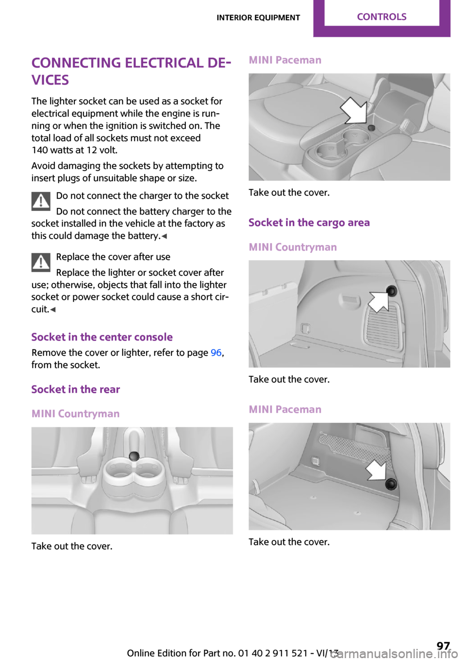
Connecting electrical de‐
vices
The lighter socket can be used as a socket for
electrical equipment while the engine is run‐
ning or when the ignition is switched on. The
total load of all sockets must not exceed
140 watts at 12 volt.
Avoid damaging the sockets by attempting to
insert plugs of unsuitable shape or size.
Do not connect the charger to the socket
Do not connect the battery charger to the
socket installed in the vehicle at the factory as this could damage the battery. ◀
Replace the cover after use
Replace the lighter or socket cover after
use; otherwise, objects that fall into the lighter
socket or power socket could cause a short cir‐
cuit. ◀
Socket in the center console
Remove the cover or lighter, refer to page 96,
from the socket.
Socket in the rear
MINI Countryman
Take out the cover.
MINI Paceman
Take out the cover.
Socket in the cargo area
MINI Countryman
Take out the cover.
MINI Paceman
Take out the cover.
Seite 97Interior equipmentControls97
Online Edition for Part no. 01 40 2 911 521 - VI/13
Page 98 of 218

Cargo areaCargo cover Do not place objects on the covers
Do not place objects on the cover; if you
do so, they may pose a danger to vehicle occu‐
pants during braking or evasive maneuvers or
damage the cover. ◀
When the tailgate is opened, the cargo cover is
raised.
To load bulky luggage, the cover can be re‐
moved.1.Detach the securing straps from the tail‐
gate.2.Lift the cover slightly, arrow 1, and pull it
back and out of the bracket, arrow 2.
MINI Countryman:
MINI Paceman:
MINI Countryman: rear seat backrests
Danger of pinching
Before folding down the rear seat back‐
rests, ensure that path of movement of the
backrests is clear. Especially when the middle
section is folded down, ensure that no one is
located in or reaches into the path of move‐ ment of the rear seat backrests. Otherwise, in‐
juries or damage may result. ◀
Observe the instructions concerning the
safety belt
Observe the instructions concerning the safety
belt, refer to page 38. Otherwise, personal pro‐
tection may be compromised. ◀
The rear seat backrest is divided at a ratio of 40-20-40.
When the outer rear seat backrests are folded down, it is not permissible for a person to travel
on the center seat.
Remove the third head restraint, refer to
page 41, if necessary.
Open the center safety belt and insert it in the
belt holder on the headliner, refer to page 39.
Enlarge the cargo area by adjusting the rear
seat backrests to a more upright position.
The backrests can be adjusted to 10 different
positions between the comfort and transport
positions and they can be folded down.
In the comfort position, the backrests are tilted
back to the greatest possible angle and in the
transport position they are nearly vertical.Seite 98ControlsInterior equipment98
Online Edition for Part no. 01 40 2 911 521 - VI/13