driving MINI Countryman 2014 Owner's Manual
[x] Cancel search | Manufacturer: MINI, Model Year: 2014, Model line: Countryman, Model: MINI Countryman 2014Pages: 218, PDF Size: 5.45 MB
Page 5 of 218
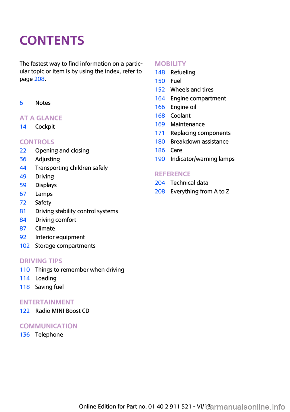
ContentsThe fastest way to find information on a partic‐
ular topic or item is by using the index, refer to
page 208.6Notes
At a glance
14Cockpit
Controls
22Opening and closing36Adjusting44Transporting children safely49Driving59Displays67Lamps72Safety81Driving stability control systems84Driving comfort87Climate92Interior equipment102Storage compartments
Driving tips
110Things to remember when driving114Loading118Saving fuel
Entertainment
122Radio MINI Boost CD
Communication
136TelephoneMobility148Refueling150Fuel152Wheels and tires164Engine compartment166Engine oil168Coolant169Maintenance171Replacing components180Breakdown assistance186Care190Indicator/warning lamps
Reference
204Technical data208Everything from A to Z
Online Edition for Part no. 01 40 2 911 521 - VI/13
Page 8 of 218
your skin by washing thoroughly with soap and
water.
Service and warranty
We recommend that you read this publication
thoroughly. Your vehicle is covered by the fol‐
lowing warranties:▷New Vehicle Limited Warranty.▷Rust Perforation Limited Warranty.▷Federal Emissions System Defect Warranty.▷Federal Emissions Performance Warranty.▷California Emission Control System Limited
Warranty.
Detailed information about these warranties is
listed in the Service and Warranty Information
Booklet for US models or in the Warranty and
Service Guide Booklet for Canadian models.
Your vehicle has been specifically adapted and
designed to meet the particular operating con‐
ditions and homologation requirements in your
country and continental region in order to de‐
liver the full driving pleasure while the vehicle is
operated under those conditions. If you wish to
operate your vehicle in another country or re‐
gion, you may be required to adapt your vehi‐
cle to meet different prevailing operating con‐
ditions and homologation requirements. You
should also be aware of any applicable war‐
ranty limitations or exclusions for such country
or region. In such case, please contact Cus‐
tomer Relations for further information.
Maintenance
Maintain the vehicle regularly to sustain the
road safety, operational reliability and the New
Vehicle Limited Warranty.
Specifications for required maintenance meas‐
ures:
▷MINI Maintenance system▷Service and Warranty Information Booklet
for US models▷Warranty and Service Guide Booklet for
Canadian modelsIf the vehicle is not maintained according to
these specifications, this could result in serious
damage to the vehicle. Such damage is not
covered by the MINI New Vehicle Limited War‐
ranty.
Data memory
Numerous electronic components in your vehi‐
cle contain data memories that store technical
information on the vehicle condition, events and faults, either temporarily or permanently.This technical information generally documents
the state of a component, a module, a system
or the environment.▷Operating conditions of system compo‐
nents, such as filling levels.▷Status messages from the vehicle and its in‐
dividual components, such as wheel rpm/
speed, motion delay, transverse accelera‐
tion.▷Malfunctions and defects in important sys‐
tem components, such as lights and brakes.▷Vehicle responses to special driving situa‐
tions, such as airbag deployment, use of
the stability control systems.▷Ambient conditions, such as the tempera‐
ture.
These data are of a technical nature only and
are used to detect and eliminate faults and to
optimize vehicle functions. Travel profiles of
routes driven with the vehicle cannot be cre‐
ated from these data. If services are used, for
instance in the event of repairs, service proc‐
esses, warranty cases, quality assurance, etc.,
this technical information can be read out from
the event and fault data memories by service
personnel, including the manufacturer, using
special diagnosis tools. This service personnel
can provide you with more information if
needed. After troubleshooting, the information
in the fault memory is cleared or overwritten
continuously.
Seite 8Notes8
Online Edition for Part no. 01 40 2 911 521 - VI/13
Page 9 of 218
Situations are conceivable during the use of the
vehicle in which these technical data could be‐
come associated with a specific person in com‐
bination with other information, such as an ac‐
cident report, damage to the vehicle, witness
accounts, etc., possibly with the involvement of
an authorized expert.
Additional functions that are contractually
agreed with the customer, such as vehicle lo‐
calization in the event of an emergency, permit
the transfer of certain vehicle data out of the
vehicle.
Event Data Recorder EDR
This vehicle is equipped with an event data re‐
corder EDR. The main purpose of an EDR is to
record, in certain crash or near crash-like situa‐
tions, such as an air bag deployment or hitting
a road obstacle, data that will assist in under‐
standing how a vehicle's systems performed.
The EDR is designed to record data related to
vehicle dynamics and safety systems for a short
period of time, typically 30 seconds or less.
The EDR in this vehicle is designed to record
such data as:▷How various systems in your vehicle were
operating.▷Whether or not the driver and passenger
safety belts were fastened.▷How far, if at all, the driver was depressing
the accelerator and/or brake pedal.▷How fast the vehicle was traveling.
These data can help provide a better under‐
standing of the circumstances in which crashes
and injuries occur.
EDR data are recorded by your vehicle only if a
nontrivial crash situation occurs; no data are re‐
corded by the EDR under normal driving condi‐
tions and no personal data, e.g., name, gender,
age, and crash location, are recorded.
However, other parties, such as law enforce‐
ment, could combine the EDR data with the
type of personally identifying data routinely ac‐
quired during a crash investigation.
To read data recorded by an EDR, special
equipment is required, and access to the vehi‐
cle or the EDR is needed. In addition to the ve‐
hicle manufacturer, other parties, such as law
enforcement, that have the special equipment,
can read the information if they have access to
the vehicle or the EDR.
Reporting safety defects
For US customers The following only applies to vehicles owned
and operated in the US.
If you believe that your vehicle has a defect
which could cause a crash or could cause injury or death, you should immediately inform the
National Highway Traffic Safety Administration
NHTSA, in addition to notifying BMW of North
America, LLC, P.O. Box 1227, Westwood, New
Jersey 07675-1227, Telephone
1-800-831-1117.
If NHTSA receives similar complaints, it may
open an investigation, and if it finds that a
safety defect exists in a group of vehicles, it may order a recall and remedy campaign.
However, NHTSA cannot become involved in
individual problems between you, your dealer,
or BMW of North America, LLC.
To contact NHTSA, you may call the Vehicle
Safety Hotline toll-free at 1-888-327-4236
(TTY: 1-800-424-9153); go to http://www.safe‐
rcar.gov; or write to: Administrator, NHTSA, 400
Seventh Street, SW., Washington, DC 20590. You can also obtain other information about
motor vehicle safety from http://www.safe‐
rcar.gov
For Canadian customers Canadian customers who wish to report a
safety- related defect to Transport Canada, De‐
fect Investigations and Recalls, may telephoneSeite 9Notes9
Online Edition for Part no. 01 40 2 911 521 - VI/13
Page 13 of 218
At a glanceControlsDriving tipsEntertainmentCommunicationMobilityReferenceOnline Edition for Part no. 01 40 2 911 521 - VI/13
Page 18 of 218
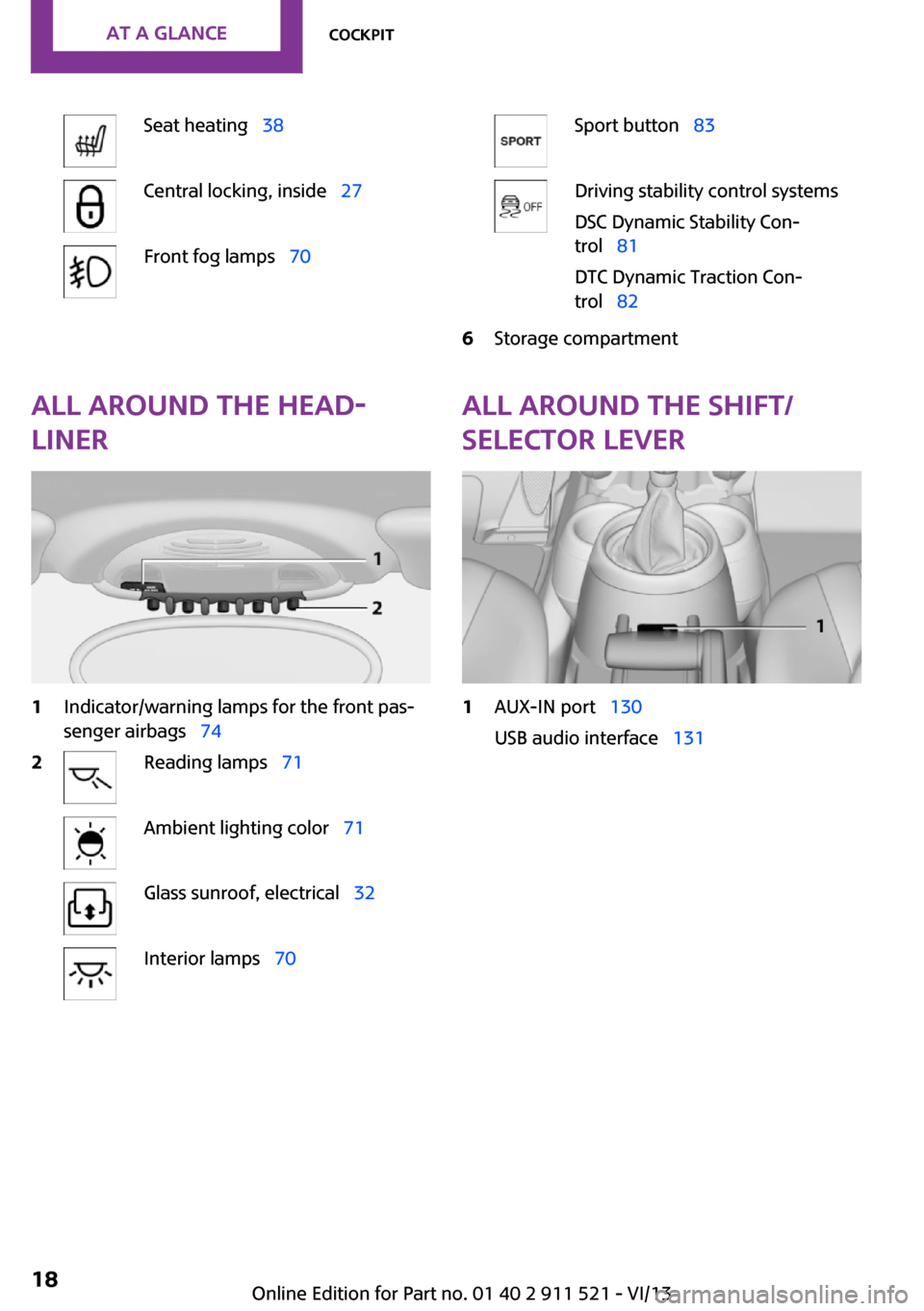
Seat heating 38Central locking, inside 27Front fog lamps 70Sport button 83Driving stability control systems
DSC Dynamic Stability Con‐
trol 81
DTC Dynamic Traction Con‐
trol 826Storage compartmentAll around the head‐
liner1Indicator/warning lamps for the front pas‐
senger airbags 742Reading lamps 71Ambient lighting color 71Glass sunroof, electrical 32Interior lamps 70All around the shift/
selector lever1AUX-IN port 130
USB audio interface 131Seite 18At a glanceCockpit18
Online Edition for Part no. 01 40 2 911 521 - VI/13
Page 21 of 218
At a glanceControlsDriving tipsEntertainmentCommunicationMobilityReferenceOnline Edition for Part no. 01 40 2 911 521 - VI/13
Page 28 of 218
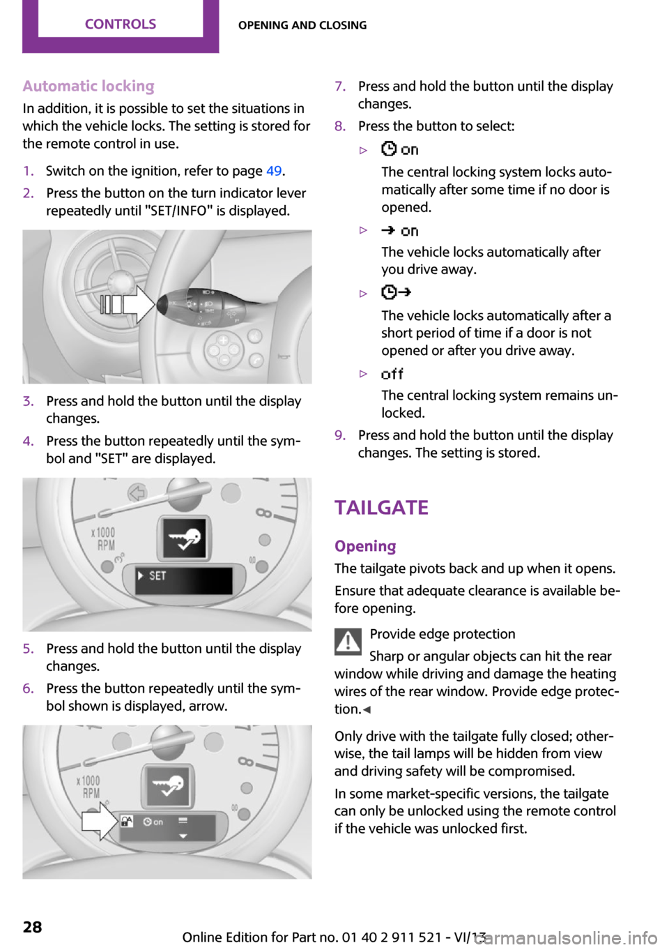
Automatic locking
In addition, it is possible to set the situations in
which the vehicle locks. The setting is stored for
the remote control in use.1.Switch on the ignition, refer to page 49.2.Press the button on the turn indicator lever
repeatedly until "SET/INFO" is displayed.3.Press and hold the button until the display
changes.4.Press the button repeatedly until the sym‐
bol and "SET" are displayed.5.Press and hold the button until the display
changes.6.Press the button repeatedly until the sym‐
bol shown is displayed, arrow.7.Press and hold the button until the display
changes.8.Press the button to select:▷
The central locking system locks auto‐
matically after some time if no door is
opened.▷
The vehicle locks automatically after
you drive away.▷
The vehicle locks automatically after a
short period of time if a door is not
opened or after you drive away.▷
The central locking system remains un‐
locked.9.Press and hold the button until the display
changes. The setting is stored.
Tailgate
Opening
The tailgate pivots back and up when it opens.
Ensure that adequate clearance is available be‐
fore opening.
Provide edge protection
Sharp or angular objects can hit the rear
window while driving and damage the heating
wires of the rear window. Provide edge protec‐
tion. ◀
Only drive with the tailgate fully closed; other‐
wise, the tail lamps will be hidden from view
and driving safety will be compromised.
In some market-specific versions, the tailgate
can only be unlocked using the remote control
if the vehicle was unlocked first.
Seite 28ControlsOpening and closing28
Online Edition for Part no. 01 40 2 911 521 - VI/13
Page 31 of 218
If a remote control accidentally left in the cargo
area is detected in the locked vehicle after the
tailgate is closed, the tailgate opens again
slightly. The hazard warning system flashes and
an acoustic signal sounds.
Power windows and electrical glass
sunroof
When the engine is switched off, the windows
and the sunroof can be operated as long as
neither the doors nor the tailgate are opened.
When the door and tailgate are closed again
and the remote control is detected inside the
vehicle, the windows and the sunroof can be
operated again.
Insert the remote control into the ignition lock
to be able to operate the windows and the sun‐
roof while the engine is switched off and the
doors are open.
Switching on the radio ready state Press the Start/Stop button to switch on the
radio ready state, refer to page 49.
Do not depress the brake or the clutch; other‐
wise, the engine will start.
Starting the engine The engine can be started or the ignition can
be switched on, refer to page 49, when a re‐
mote control is inside the vehicle. It is not nec‐
essary to insert a remote control into the igni‐
tion lock.
Switching off the engine in cars with
automatic transmission
The engine can only be switched off with the
selector lever in position P, refer to page 56.
To switch off the engine with the selector lever
in position N, the remote control must be in‐
serted in the ignition lock.Before driving a vehicle with automatic
transmission into a car wash1.Insert the remote control into the ignition
switch.2.Depress the brake pedal.3.Move the selector lever to position N.4.Switch the engine off.
The vehicle can roll.
Malfunction The Comfort Access functions can be disturbed
by local radio waves, such as by a mobile
phone in the immediate vicinity of the remote
control or when a mobile phone is being
charged in the vehicle.
If this occurs, open or close the vehicle using
the buttons on the remote control or use the
integrated key in the door lock.
To start the engine afterward, insert the remote
control into the ignition switch.
Warning lamps The warning lamp in the instrument
cluster lights up when you attempt to
start the engine: the engine cannot be
started.
The remote control is not in the vehicle or has a
malfunction. Take the remote control with you
inside the vehicle or have it checked. If neces‐
sary, insert another remote control into the ig‐
nition switch.
The warning lamp in the instrument
cluster lights up while the engine is run‐
ning: the remote control is no longer in‐
side the vehicle.
After switching off the engine, the engine can
only be started again within approx. 10 sec‐
onds if no door has been opened.
The indicator lamp lights up: replace
the remote control battery.
Seite 31Opening and closingControls31
Online Edition for Part no. 01 40 2 911 521 - VI/13
Page 36 of 218
AdjustingVehicle equipment
This chapter describes all series equipment as
well as country-specific and special equipment
offered for this model series.Therefore, it also
describes equipment that may not be found in
your vehicle, for instance due to the selected
special equipment or the country version. This
also applies to safety-related functions and sys‐
tems.
Sitting safely The ideal seating position can make a vital con‐
tribution to relaxed, fatigue-free driving.
The seating position plays an important role in
an accident in combination with:▷Safety belts, refer to page 38▷Head restraints, refer to page 41.▷Airbags, refer to page 72.
Seats
Note before adjusting Do not adjust the seat while driving
Never attempt to adjust the driver's seat
while driving. The seat could respond with un‐
expected movement and the ensuing loss of
vehicle control could lead to an accident. ◀
Do not incline the backrest too far to the
rear
Do not incline the backrest on the front passen‐
ger side too far to the rear during driving. Oth‐
erwise, there is the danger of sliding under the
safety belt in an accident. This would eliminate
the protection normally provided by the belt. ◀
Front seat adjustment
Forward/backward
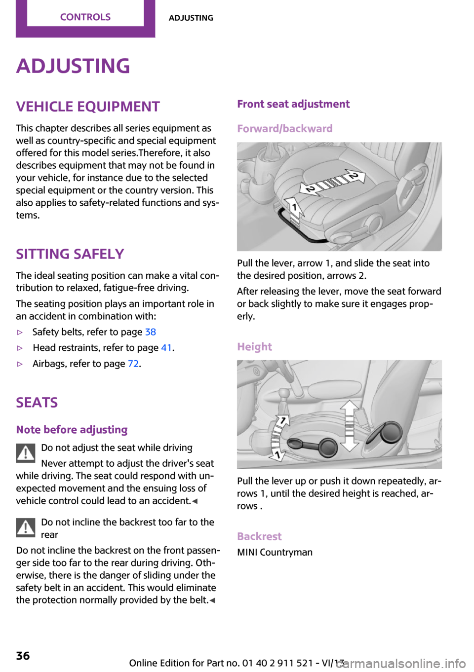
Pull the lever, arrow 1, and slide the seat into
the desired position, arrows 2.
After releasing the lever, move the seat forward
or back slightly to make sure it engages prop‐
erly.
Height
Pull the lever up or push it down repeatedly, ar‐
rows 1, until the desired height is reached, ar‐
rows .
Backrest MINI Countryman
Seite 36ControlsAdjusting36
Online Edition for Part no. 01 40 2 911 521 - VI/13
Page 38 of 218
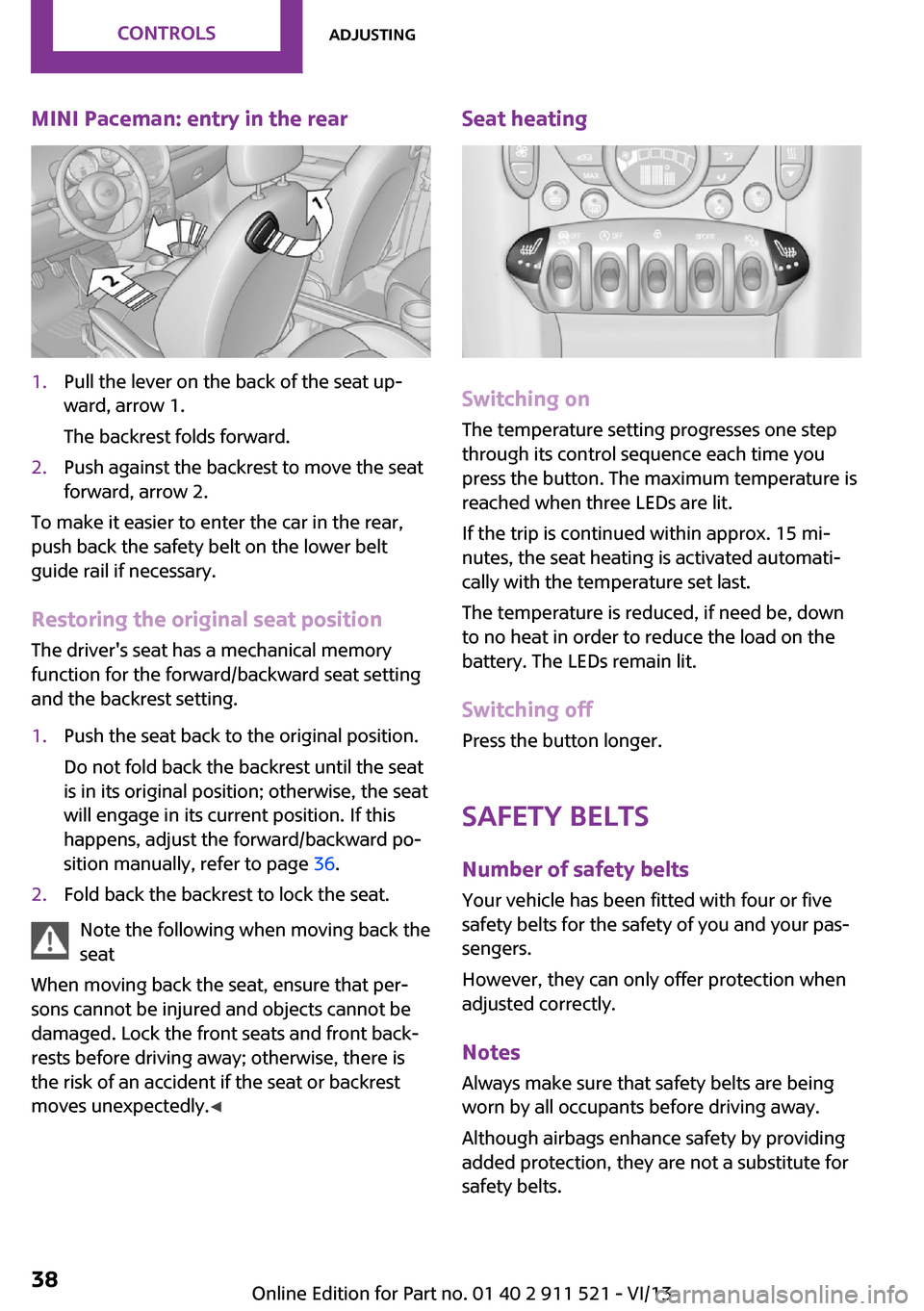
MINI Paceman: entry in the rear1.Pull the lever on the back of the seat up‐
ward, arrow 1.
The backrest folds forward.2.Push against the backrest to move the seat
forward, arrow 2.
To make it easier to enter the car in the rear,
push back the safety belt on the lower belt
guide rail if necessary.
Restoring the original seat position The driver's seat has a mechanical memory
function for the forward/backward seat setting
and the backrest setting.
1.Push the seat back to the original position.
Do not fold back the backrest until the seat
is in its original position; otherwise, the seat
will engage in its current position. If this
happens, adjust the forward/backward po‐
sition manually, refer to page 36.2.Fold back the backrest to lock the seat.
Note the following when moving back the
seat
When moving back the seat, ensure that per‐
sons cannot be injured and objects cannot be
damaged. Lock the front seats and front back‐
rests before driving away; otherwise, there is
the risk of an accident if the seat or backrest
moves unexpectedly. ◀
Seat heating
Switching on
The temperature setting progresses one step
through its control sequence each time you
press the button. The maximum temperature is
reached when three LEDs are lit.
If the trip is continued within approx. 15 mi‐
nutes, the seat heating is activated automati‐
cally with the temperature set last.
The temperature is reduced, if need be, down
to no heat in order to reduce the load on the
battery. The LEDs remain lit.
Switching off
Press the button longer.
Safety beltsNumber of safety belts
Your vehicle has been fitted with four or five
safety belts for the safety of you and your pas‐
sengers.
However, they can only offer protection when
adjusted correctly.
NotesAlways make sure that safety belts are beingworn by all occupants before driving away.
Although airbags enhance safety by providing
added protection, they are not a substitute for
safety belts.
Seite 38ControlsAdjusting38
Online Edition for Part no. 01 40 2 911 521 - VI/13