ESP MINI Countryman 2015 (Mini Connected) Service Manual
[x] Cancel search | Manufacturer: MINI, Model Year: 2015, Model line: Countryman, Model: MINI Countryman 2015Pages: 283, PDF Size: 6.76 MB
Page 216 of 283
FuelFuel recommendationVehicle equipment This chapter describes all series equipment as
well as country-specific and special equipment
offered for this model series. Therefore, it also
describes equipment that may not be found in
your vehicle, for instance due to the selected
special equipment or the country version. This
also applies to safety-related functions and sys‐
tems.
When using the features and systems described
here, adhere to local regulations.
GasolineFor the best fuel economy, the gasoline should
be sulfur-free or very low in sulfur content.
Do not use fuels that are labeled at the fuel
pump as containing metals.
Only refuel with lead-free gasoline with‐
out metal additives
Do not refuel with leaded gasoline or gasoline
with metal additives, e. g., manganese or iron;
otherwise, the catalytic converter and other
components will be permanently damaged. ◀
Fuels with a maximum ethanol content of
10 %, i.e., E10, may be used for refueling.
The ethanol should fulfill the following quality
standards:
US: ASTM 4806–xx
CAN: CGSB-3.511–xx
xx: always adhere to the currently applicable
standard.
Do not refuel with ethanol E85
Do not refuel with E85, i.e., fuel with an
ethanol content of 85 %, or with Flex Fuel, as
this would damage the engine and fuel supply
system. ◀The engine is knock controlled. Therefore, you
can refuel with different recommended fuel
grades.
Recommended fuel grade
The manufacturer of your MINI recommends:▷AKI 91.▷John Cooper Works AKI 93.
Minimum fuel grade
The manufacturer of your MINI recommends
AKI 89.
Minimum fuel grade
Do not fill up with fuel below the speci‐
fied minimum quality; otherwise, the engine
may not run properly. ◀
If you use gasoline with this minimum AKI rat‐
ing, the engine may produce knocking sounds
when starting at high outside temperatures.
This has no effect on the engine life.
Minimum fuel grade
The use of poor-quality fuels may result in
harmful engine deposits or damage. Addition‐
ally, problems relating to drivability, starting
and stalling, especially under certain environ‐
mental conditions such as high ambient tem‐
perature and high altitude, may occur.
If drivability problems are encountered, we rec‐
ommend switching to a high quality gasoline
brand and a higher octane grade — AKI num‐
ber — for a few tank fills. To avoid harmful en‐
gine deposits, it is highly recommended to pur‐
chase gasoline from BP or Top Tier retailers.
Failure to comply with these recommendations
may result in the need for unscheduled mainte‐
nance. ◀
Seite 214MOBILITYFuel214
Online Edition for Part no. 01 40 2 961 110 - II/15
Page 218 of 283
Wheels and tiresVehicle equipment
This chapter describes all series equipment as
well as country-specific and special equipment
offered for this model series. Therefore, it also
describes equipment that may not be found in
your vehicle, for instance due to the selected
special equipment or the country version. This
also applies to safety-related functions and sys‐
tems.
When using the features and systems described
here, adhere to local regulations.
Tire inflation pressure
Safety information It is not merely the tires' service life, but also
driving comfort and, to a great extent, driving
safety that depend on the condition of the tires
and the maintenance of the specified tire pres‐
sure.
Checking the pressure Tires naturally lose pressure uniformly across all
four tires.
Check the tire inflation pressure regularly
Regularly check the tire inflation pressure
and correct it as needed: at least twice a month
and before a long trip. If you fail to observe this
precaution, you may be driving on tires with in‐
correct tire pressures, a condition that may not
only compromise your vehicle's driving stabil‐
ity, but also lead to tire damage and the risk of
an accident.
Do not drive with depressurized or flat tires, ex‐
cept for run-flat tires. A flat tire will seriously
impair your vehicle's handling and braking re‐
sponse. Attempts to drive on a flat tire can lead
to a loss of control over the vehicle. ◀Tires warm up during driving and the tire infla‐
tion pressure increases as the temperature
rises. The tire inflation pressure specifications
apply to cold tires or tires at ambient tempera‐
ture.
Only check the tire inflation pressure when the
tires are cold. This means after a maximum of
1.25 miles/2 km driving or when the vehicle
has been parked for at least 2 hours. When the
tires are warm, the tire inflation pressure is
higher.
After correcting the tire inflation pressure, reset
the Tire Pressure Monitor, refer to page 87
or reinitialize the Flat Tire Monitor, refer to
page 85.
Pressure specifications
The tables below provide all the correct infla‐
tion pressures for the specified tire sizes at am‐
bient temperature.
The inflation pressures apply to the tire sizes
approved and tire brands recommended by the
manufacturer of the MINI; a list of these is
available from the service center.
For correct identification of the right tire infla‐
tion pressures, observe the following:▷Tire sizes of your vehicle▷Maximum allowable driving speed
Tire inflation pressures for driving up to
100 mph or 160 km/h
For normal driving up to 100 mph/160 km/h,
adjust pressures to the respective tire inflation
pressures listed on the following pages in the
column for traveling speeds up to 100 mph/
160 km/h to achieve optimum driving comfort.
These tire inflation pressures can also be found
on the driver's side door pillar when the driver's
door is open.
Seite 216MOBILITYWheels and tires216
Online Edition for Part no. 01 40 2 961 110 - II/15
Page 223 of 283

Conform to Federal Safety Requirements
All passenger car tires must conform to
Federal Safety Requirements in addition to
these grades. ◀
Treadwear
The treadwear grade is a comparative rating based on the wear rate of the tire when tested
under controlled conditions on a specified gov‐
ernment test course. For example, a tire graded
150 would wear one and one-half (1 1/2) times
as well on the government course as a tire graded 100. The relative performance of tires
depends upon the actual conditions of their
use, however, and may depart significantly
from the norm due to variations in driving hab‐
its, service practices and differences in road
characteristics and climate.
TractionThe traction grades, from highest to lowest, are
AA, A, B, and C.
Those grades represent the tire's ability to stop
on wet pavement as measured under control‐
led conditions on specified government test
surfaces of asphalt and concrete. A tire marked
C may have poor traction performance.
The traction grade assigned to this tire is based
on straight-ahead braking traction tests, and
does not include acceleration, cornering, hy‐
droplaning, or peak traction characteristics.
Temperature
The temperature grades are A, the highest, B,
and C, representing the tire's resistance to the
generation of heat and its ability to dissipate
heat when tested under controlled conditions
on a specified indoor laboratory test wheel.
Sustained high temperature can cause the ma‐
terial of the tire to degenerate and reduce tire
life, and excessive temperature can lead to
sudden tire failure. The grade C corresponds to
a level of performance which all passenger car
tires must meet under the Federal Motor Vehi‐cle Safety Standard No. 109. Grades B and A
represent higher levels of performance on the
laboratory test wheel than the minimum re‐
quired by law.
Temperature grade for this tire
The temperature grade for this tire is es‐
tablished for a tire that is properly inflated and
not overloaded. Excessive speed, underinfla‐
tion, or excessive loading, either separately or
in combination, can cause heat buildup and
possible tire failure. ◀
RSC – Run-flat tires
The symbol identifying run-flat tires is a circle
with the letters RSC on the sidewall, refer to
page 224.
M+S
Winter and all-season tires.
These have better winter properties than
summer tires.
XL
Designation for specially reinforced tires.
Tire treadSummer tiresThe tread depth should not be less than
0.12 in/3 mm, although European legislation,
for example, requires a minimum tread depth
of only 0.063 in/1.6 mm. At tread depths less
than 0.12 in/3 mm, there is a great danger of
hydroplaning even in low water depths and at
raised speeds.
Winter tires
The suitability of winter tires for winter driving
is reduced noticeably when their tread depth
becomes less than 0.16 in/4 mm.Seite 221Wheels and tiresMOBILITY221
Online Edition for Part no. 01 40 2 961 110 - II/15
Page 225 of 283
Changing wheels and
tires
Mounting Information on mounting tires
Have mounting and balancing performed
only by a service center or tire specialist.
If this work is not carried out properly, there is
the danger of subsequent damage and related
safety hazards. ◀
Wheel and tire combination Information on the right wheel and tire combi‐
nation and rim version for your vehicle can be
obtained from the service center.
Incorrect wheel and tire combinations impair
the function of a variety of systems such as ABS
or DSC.
To maintain good handling and vehicle re‐
sponse, use only tires with a single tread con‐
figuration from a single manufacturer.
Following tire damage, have the original wheel
and tire combination remounted on the vehicle
as soon as possible.
Approved wheels and tires
The manufacturer of your vehicle recom‐
mends that you use only wheels and tires that
have been approved for your particular vehicle
model.
For example, despite having the same official
size ratings, variations can lead to body contact
and with it, the risk of severe accidents.
The manufacturer of your vehicle cannot evalu‐
ate non-approved wheels and tires to deter‐
mine if they are suited for use, and therefore
cannot ensure the operating safety of the vehi‐
cle if they are mounted. ◀Wheels with electronics for TPM Tire
Pressure Monitor
When mounting new tires or changing from
summer to winter tires or vice versa, only use
wheels with TPM electronics; otherwise, the
Tire Pressure Monitor will not be able to detect
a flat tire, refer to page 86. Your service center
will be glad to advise you.
Recommended tire brands
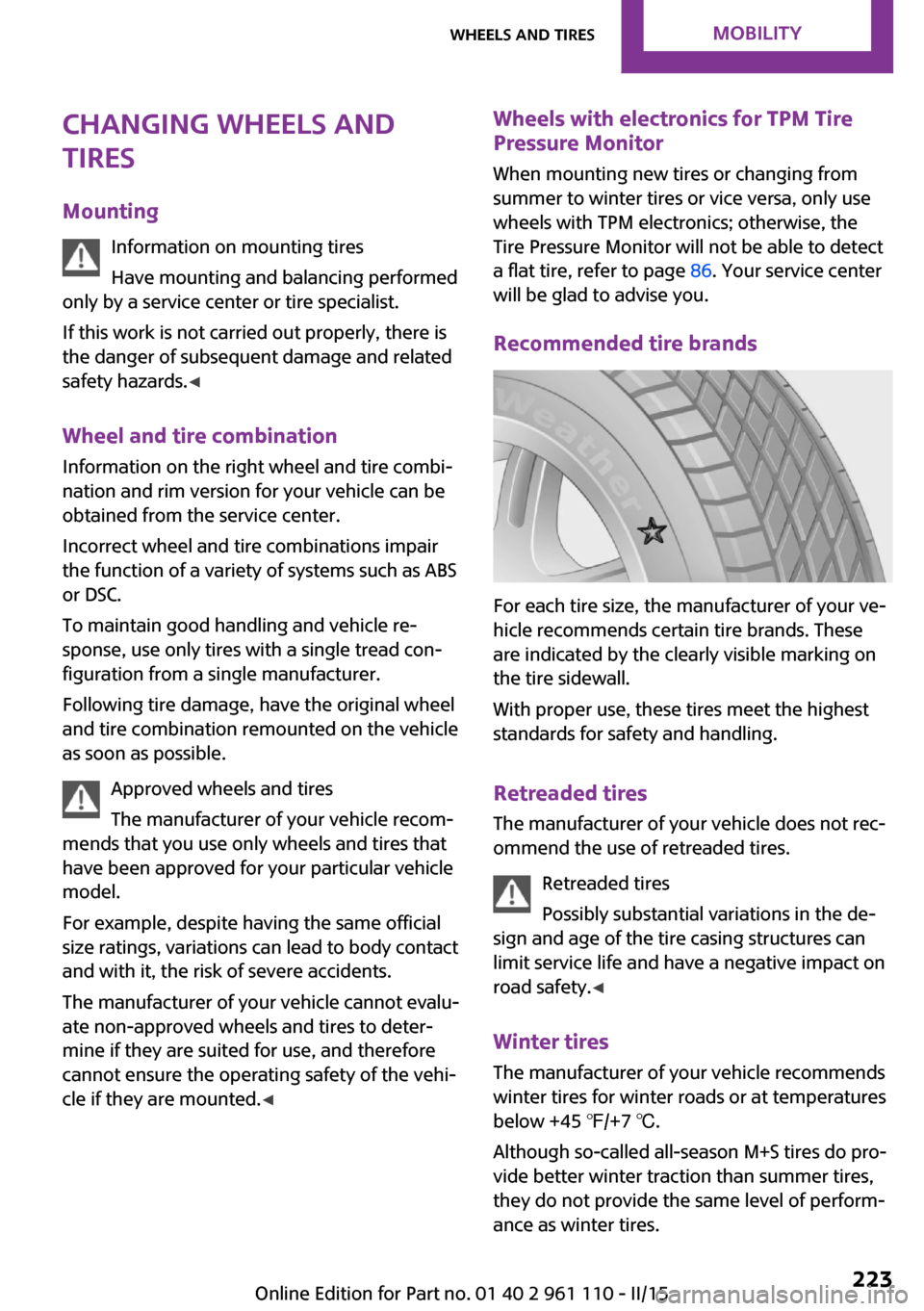
For each tire size, the manufacturer of your ve‐
hicle recommends certain tire brands. These
are indicated by the clearly visible marking on
the tire sidewall.
With proper use, these tires meet the highest
standards for safety and handling.
Retreaded tires
The manufacturer of your vehicle does not rec‐
ommend the use of retreaded tires.
Retreaded tires
Possibly substantial variations in the de‐
sign and age of the tire casing structures can
limit service life and have a negative impact on
road safety. ◀
Winter tires The manufacturer of your vehicle recommends
winter tires for winter roads or at temperatures
below +45 ℉/+7 ℃.
Although so-called all-season M+S tires do pro‐
vide better winter traction than summer tires,
they do not provide the same level of perform‐
ance as winter tires.
Seite 223Wheels and tiresMOBILITY223
Online Edition for Part no. 01 40 2 961 110 - II/15
Page 226 of 283
Maximum speed of winter tires
If the maximum speed of the vehicle is higher
than the permissible speed for the winter tires,
then display a corresponding sign in the field of
vision. You can obtain this sign from the tire
specialist or from your service center.
Maximum speed for winter tires
Do not exceed the maximum speed for
the winter tires; otherwise, tire damage and ac‐
cidents can occur. ◀
Run-flat tires When mounting new tires or changing fromsummer to winter tires or vice versa, use run-
flat tires for your own safety. Also, a compact
wheel is not available in case of a flat tire. Your
service center will be glad to advise you.
Rotating wheels between axles
Different wear patterns occur on the front and
rear axles, depending on the individual condi‐
tions of use.
To ensure even wear on the tires, the wheels
can be rotated between the axles. Your service
center will be glad to advise you.
After changing the tires, check the tire inflation
pressure and correct it if necessary.
Storage Store wheels and tires in a cool, dry place with
as little exposure to light as possible.
Always protect tires against all contact with oil,
grease and fuels.
Do not exceed the maximum tire inflation pres‐
sure indicated on the side wall of the tire.Run-flat tires
Label
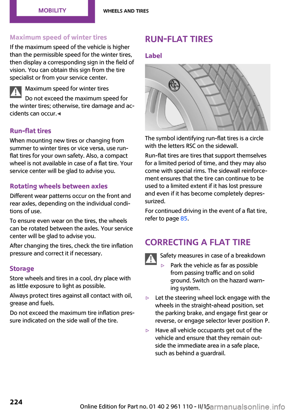
The symbol identifying run-flat tires is a circle
with the letters RSC on the sidewall.
Run-flat tires are tires that support themselves
for a limited period of time, and they may also
come with special rims. The sidewall reinforce‐
ment ensures that the tire can continue to be
used to a limited extent if it has lost pressure
and even if it has become completely depres‐
surized.
For continued driving in the event of a flat tire,
refer to page 85.
Correcting a flat tire Safety measures in case of a breakdown
▷Park the vehicle as far as possible
from passing traffic and on solid
ground. Switch on the hazard warn‐
ing system.▷Let the steering wheel lock engage with the
wheels in the straight-ahead position, set
the parking brake, and engage first gear or
reverse, or engage selector lever position P.▷Have all vehicle occupants get out of the
vehicle and ensure that they remain out‐
side the immediate area in a safe place,
such as behind a guardrail.Seite 224MOBILITYWheels and tires224
Online Edition for Part no. 01 40 2 961 110 - II/15
Page 232 of 283
Engine oilEngine oil
Vehicle equipment This chapter describes all series equipment as
well as country-specific and special equipment
offered for this model series. Therefore, it also
describes equipment that may not be found in
your vehicle, for instance due to the selected
special equipment or the country version. This
also applies to safety-related functions and sys‐
tems.
When using the features and systems described
here, adhere to local regulations.
General information
Engine oil consumption depends on the driving
style and the conditions of use. A highly sporty
driving style, for example, results in considera‐
bly higher engine oil consumption.
Therefore, regularly check the engine oil level
after refueling.
Checking the oil level with a dip stick1.Park the vehicle on level ground when the
engine is at operating temperature, i.e., af‐
ter driving continuously for at least
6 2 miles/10 km.2.Switch the engine off.3.After approx. 5 minutes, pull out the dip
stick and wipe it off with a lint-free cloth,
paper towel, etc.4.Carefully insert the dip stick all the way into
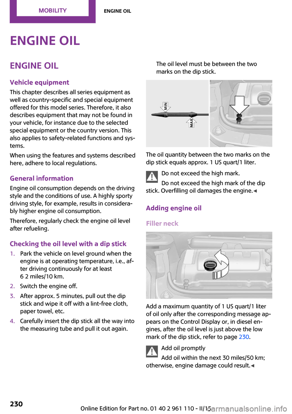
the measuring tube and pull it out again.The oil level must be between the two
marks on the dip stick.
The oil quantity between the two marks on the
dip stick equals approx. 1 US quart/1 liter.
Do not exceed the high mark.
Do not exceed the high mark of the dip
stick. Overfilling oil damages the engine. ◀
Adding engine oil
Filler neck
Add a maximum quantity of 1 US quart/1 liter
of oil only after the corresponding message ap‐
pears on the Control Display or, in diesel en‐
gines, after the oil level is just above the low
mark of the dip stick, refer to page 230.
Add oil promptly
Add oil within the next 30 miles/50 km;
otherwise, engine damage could result. ◀
Seite 230MOBILITYEngine oil230
Online Edition for Part no. 01 40 2 961 110 - II/15
Page 238 of 283

Lamp and bulb replace‐
ment
Notes
Lamps and bulbs Lamps and bulbs make an essential contribu‐
tion to vehicle safety. Therefore, exercise cau‐
tion when handling lights and bulbs.
The manufacturer of the vehicle recommends
that you entrust corresponding procedures to
the service center if you are unfamiliar with
them or they are not described here.
You can obtain a selection of replacement
bulbs at the service center.
Danger of burns
Only change bulbs when they are cool;
otherwise, there is the danger of getting
burned. ◀
Working on the lighting system
When working on the lighting system,
you should always switch off the lights affected
to prevent short circuits.
To avoid possible injury or equipment damage
when replacing bulbs, observe any instructions
provided by the bulb manufacturer. ◀
Do not touch the bulbs
Do not touch the glass of new bulbs with
your bare hands, as even minute amounts of
contamination will burn into the bulb's surface
and reduce its service life.
Use a clean tissue, cloth or something similar,
or hold the bulb by its base. ◀
Caring for the headlights, refer to page 251.
For bulb replacement that is not described
here, please contact the service center or a
workshop that works according to the repair
procedures of the manufacturer with corre‐
spondingly trained personnel.For checking and adjusting headlight aim,
please contact your MINI dealer.
Light-emitting diodes LEDs In some equipment, the light source is provided
by light-emitting diodes behind a cover.
These light-emitting diodes, which operate us‐
ing a concept similar to that applied in conven‐
tional lasers, are designated as Class 1 light-
emitting diodes.
Do not remove the covers
Do not remove the covers, and never
stare into the unfiltered light for several hours;
otherwise, irritation of the retina could result. ◀
Headlight glass Condensation can form on the inside of the
headlights in cool or humid weather. When the
light is switched on, the condensation evapo‐
rates after a short time. The headlights do not
need to be changed.
If the condensation in the headlights does not
evaporate after trips with the lights switched
on, and the amount of moisture in the head‐
lights increases, for example if water droplets
form, have them checked by your service cen‐
ter.
Bi-xenon headlights
These bulbs have a very long life and the likeli‐
hood of failure is very low, provided that they
are not switched on and off excessively. If a
bulb should nevertheless fail, you can continue
driving cautiously with the front fog lights, pro‐
vided this is permitted by local laws.
Do not perform work/bulb replacement
on xenon headlamps
Have any work on the xenon lighting system,
including bulb replacement, performed only by
a service center.
Due to the high voltage present in the system,
there is the danger of fatal injuries if work is
carried out improperly. ◀Seite 236MOBILITYReplacing components236
Online Edition for Part no. 01 40 2 961 110 - II/15
Page 244 of 283
9.Apply gentle pressure to the bulb while
turning it to the left and remove it.10.Insert the new bulb and mount the bulb
holder in reverse order. Ensure that the
bulb holder engages in all fasteners.
License plate lights
5-watt bulb, C 5 W
Replacing
MINI Countryman
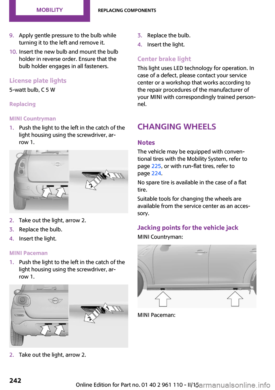
1.Push the light to the left in the catch of the
light housing using the screwdriver, ar‐
row 1.2.Take out the light, arrow 2.3.Replace the bulb.4.Insert the light.
MINI Paceman
1.Push the light to the left in the catch of the
light housing using the screwdriver, ar‐
row 1.2.Take out the light, arrow 2.3.Replace the bulb.4.Insert the light.
Center brake light
This light uses LED technology for operation. In
case of a defect, please contact your service
center or a workshop that works according to
the repair procedures of the manufacturer of
your MINI with correspondingly trained person‐
nel.
Changing wheels
Notes The vehicle may be equipped with conven‐tional tires with the Mobility System, refer to
page 225, or with run-flat tires, refer to
page 224.
No spare tire is available in the case of a flat
tire.
Suitable tools for changing the wheels are
available from the service center as an acces‐
sory.
Jacking points for the vehicle jack MINI Countryman:
MINI Paceman:
Seite 242MOBILITYReplacing components242
Online Edition for Part no. 01 40 2 961 110 - II/15
Page 248 of 283

To prevent personal injury or damage to both
vehicles, adhere strictly to the following proce‐
dure.
Do not touch live parts
To avoid the risk of potentially fatal injury,
always avoid all contact with electrical compo‐
nents while the engine is running. ◀
Preparation1.Check whether the battery of the other ve‐
hicle has a voltage of 12 volts and approxi‐
mately the same capacitance in Ah. This in‐
formation can be found on the battery.2.Switch off the engine of the assisting vehi‐
cle.3.Switch off any electronic systems/power
consumers in both vehicles.
Bodywork contact between vehicles
There must not be any contact between
the bodies of the two vehicles, otherwise there
is a danger of shorting. ◀
Connecting jumper cables
Connecting order
Connect the jumper cables in the correct
order; otherwise, there is the danger of injury
from sparking. ◀1.Open the battery cover in the engine com‐
partment to access the positive terminal.2.Unlock the tabs of the positive terminal
cover on the left and right, arrows 1, and
raise the cover, arrow 2.3.Attach one terminal clamp of the positive
jumper cable to the positive terminal of the
battery or to a starting aid terminal of the
vehicle providing assistance.4.Attach the second clamp of the positive
jumper cable to the positive terminal of the
battery of the vehicle to be started.5.Attach one terminal clamp of the negative
jumper cable to the negative terminal of
the battery, or to the corresponding engine
or body ground of the vehicle providing as‐
sistance.6.Attach the second clamp of the negative
jumper cable to the negative terminal ofSeite 246MOBILITYBreakdown assistance246
Online Edition for Part no. 01 40 2 961 110 - II/15
Page 250 of 283
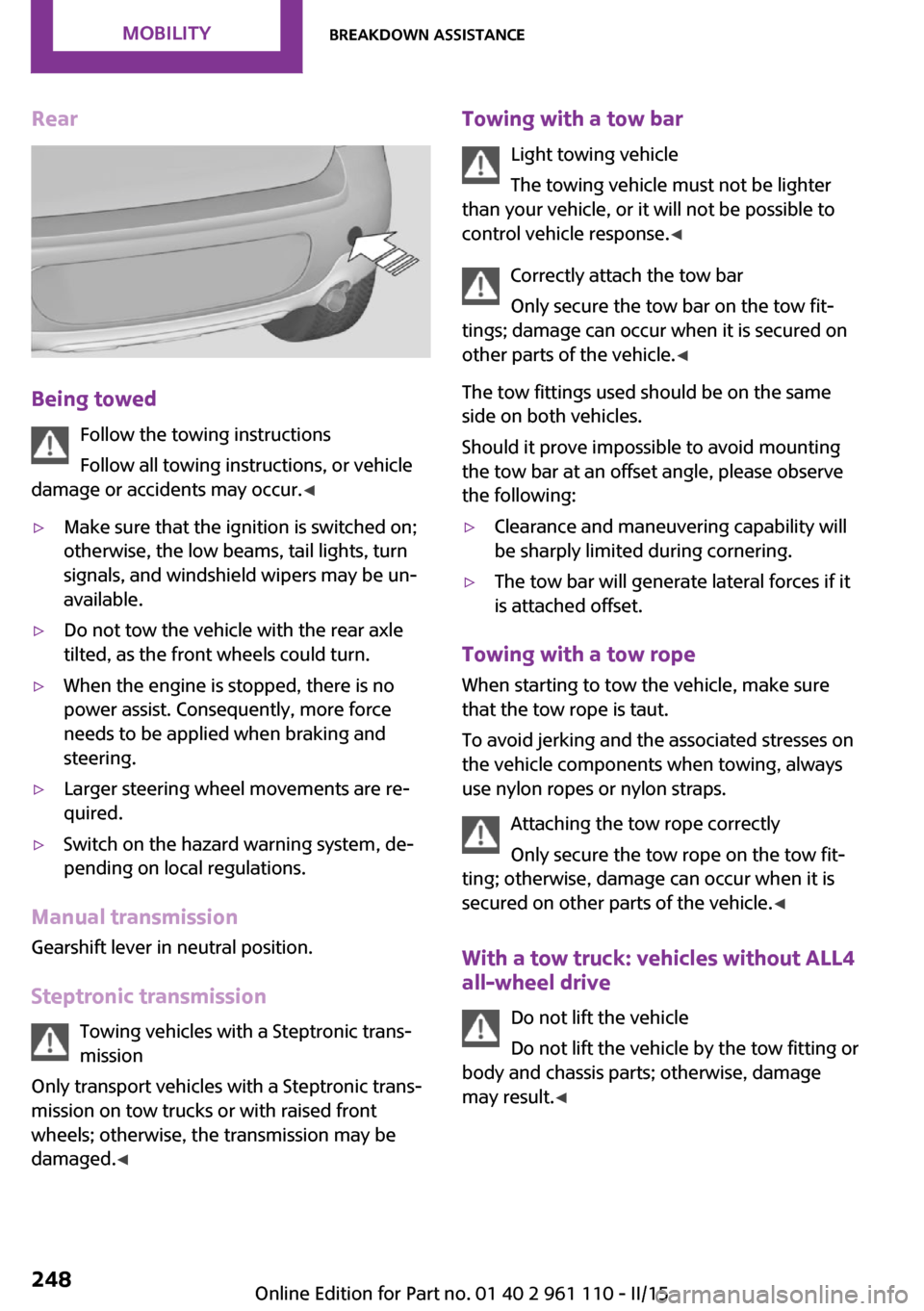
Rear
Being towedFollow the towing instructions
Follow all towing instructions, or vehicle
damage or accidents may occur. ◀
▷Make sure that the ignition is switched on;
otherwise, the low beams, tail lights, turn
signals, and windshield wipers may be un‐
available.▷Do not tow the vehicle with the rear axle
tilted, as the front wheels could turn.▷When the engine is stopped, there is no
power assist. Consequently, more force
needs to be applied when braking and
steering.▷Larger steering wheel movements are re‐
quired.▷Switch on the hazard warning system, de‐
pending on local regulations.
Manual transmission
Gearshift lever in neutral position.
Steptronic transmission Towing vehicles with a Steptronic trans‐
mission
Only transport vehicles with a Steptronic trans‐
mission on tow trucks or with raised front
wheels; otherwise, the transmission may be
damaged. ◀
Towing with a tow bar
Light towing vehicle
The towing vehicle must not be lighter
than your vehicle, or it will not be possible to
control vehicle response. ◀
Correctly attach the tow bar
Only secure the tow bar on the tow fit‐
tings; damage can occur when it is secured on
other parts of the vehicle. ◀
The tow fittings used should be on the same
side on both vehicles.
Should it prove impossible to avoid mounting
the tow bar at an offset angle, please observe
the following:▷Clearance and maneuvering capability will
be sharply limited during cornering.▷The tow bar will generate lateral forces if it
is attached offset.
Towing with a tow rope
When starting to tow the vehicle, make sure
that the tow rope is taut.
To avoid jerking and the associated stresses on
the vehicle components when towing, always
use nylon ropes or nylon straps.
Attaching the tow rope correctly
Only secure the tow rope on the tow fit‐
ting; otherwise, damage can occur when it is
secured on other parts of the vehicle. ◀
With a tow truck: vehicles without ALL4
all-wheel drive
Do not lift the vehicle
Do not lift the vehicle by the tow fitting or
body and chassis parts; otherwise, damage
may result. ◀
Seite 248MOBILITYBreakdown assistance248
Online Edition for Part no. 01 40 2 961 110 - II/15