change time MINI Countryman 2015 Owner's Manual (Mini Connected)
[x] Cancel search | Manufacturer: MINI, Model Year: 2015, Model line: Countryman, Model: MINI Countryman 2015Pages: 283, PDF Size: 6.76 MB
Page 41 of 283

Replacing the battery
The remote control for Comfort Access contains
a battery that will need to be replaced from
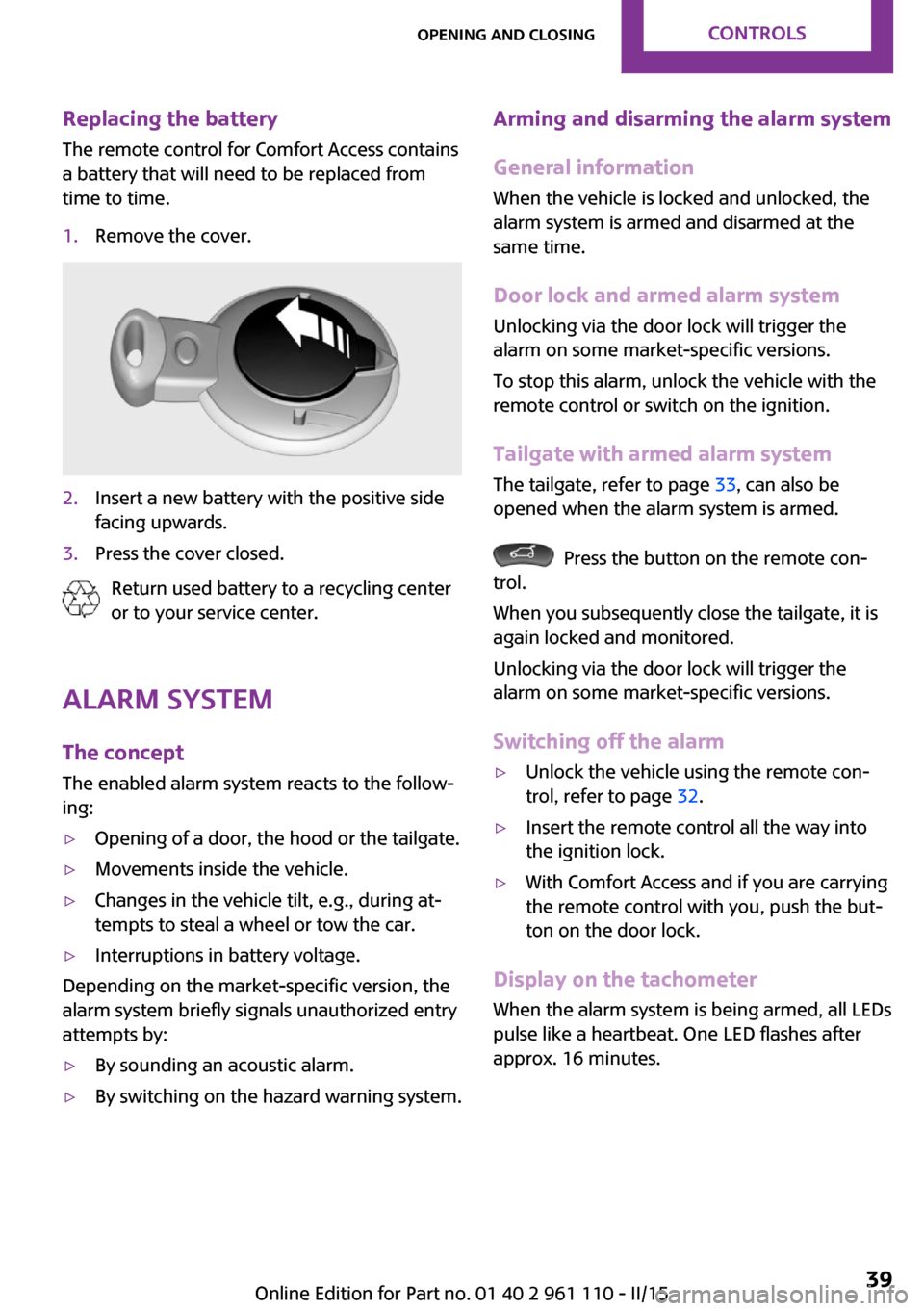
time to time.1.Remove the cover.2.Insert a new battery with the positive side
facing upwards.3.Press the cover closed.
Return used battery to a recycling center
or to your service center.
Alarm system
The concept
The enabled alarm system reacts to the follow‐
ing:
▷Opening of a door, the hood or the tailgate.▷Movements inside the vehicle.▷Changes in the vehicle tilt, e.g., during at‐
tempts to steal a wheel or tow the car.▷Interruptions in battery voltage.
Depending on the market-specific version, the
alarm system briefly signals unauthorized entry
attempts by:
▷By sounding an acoustic alarm.▷By switching on the hazard warning system.Arming and disarming the alarm system
General information
When the vehicle is locked and unlocked, the
alarm system is armed and disarmed at the
same time.
Door lock and armed alarm systemUnlocking via the door lock will trigger the
alarm on some market-specific versions.
To stop this alarm, unlock the vehicle with the
remote control or switch on the ignition.
Tailgate with armed alarm system The tailgate, refer to page 33, can also be
opened when the alarm system is armed.
Press the button on the remote con‐
trol.
When you subsequently close the tailgate, it is
again locked and monitored.
Unlocking via the door lock will trigger the
alarm on some market-specific versions.
Switching off the alarm
▷Unlock the vehicle using the remote con‐
trol, refer to page 32.▷Insert the remote control all the way into
the ignition lock.▷With Comfort Access and if you are carrying
the remote control with you, push the but‐
ton on the door lock.
Display on the tachometer
When the alarm system is being armed, all LEDs
pulse like a heartbeat. One LED flashes after
approx. 16 minutes.
Seite 39Opening and closingCONTROLS39
Online Edition for Part no. 01 40 2 961 110 - II/15
Page 63 of 283

3Activating/deactivating intermittent wipe or
the rain sensor4Cleaning the windshield and headlights
Switching on wipers
Press the wiper lever upward, arrow 1.
The lever automatically returns to its initial po‐
sition when released.
Normal wiper speed
Press up once.
The system switches to operation in the inter‐
mittent mode when the vehicle is stationary.
Fast wiper speed
Press up twice or press once beyond the resist‐
ance point.
The system switches to normal speed when the
vehicle is stationary.
Switching off wipers or brief wipe Press the wiper lever down, arrow 2.
The lever automatically returns to its initial po‐
sition when released.
▷Brief wipe: press down once.▷To switch off normal wipe: press down
once.▷To switch off fast wipe: press down twice.
Intermittent wipe or rain sensor
If the car is not equipped with a rain sensor, the
intermittent-wipe time is a preset.
If the car is equipped with a rain sensor, the
time between wipes is controlled automatically
and depends on the intensity of the rainfall.
The rain sensor is mounted on the windshield,
directly in front of the interior rearview mirror.
Deactivate the rain sensor in car washes
Deactivate the rain sensor when passing
through an automatic car wash; otherwise,
damage could be caused by undesired wiper
activation. ◀
Activating intermittent wipe or rain
sensor
Press the button, arrow 3.
The symbol is shown in the tachometer.
Setting the sensitivity of the rain sensor1.Switch on the ignition, refer to page 58.2.Press the button on the turn indicator lever
repeatedly until "SET/INFO" is displayed.3.Press and hold the button until the display
changes.4.Press the button repeatedly until the sym‐
bol and "SET" are displayed.Seite 61DrivingCONTROLS61
Online Edition for Part no. 01 40 2 961 110 - II/15
Page 67 of 283

Under normal operating conditions, fuel con‐
sumption is lowest when you are driving in po‐
sition D.
Kickdown
Kickdown is used to achieve maximum driving
performance. Press on the accelerator beyond
the resistance point at the full throttle position.
Sport program and manual mode M/S
Activating the Sport program
Move the selector lever from position D toward
the left into the M/S shifting slot.
The Sport program is activated and DS is dis‐
played. This position is recommended for a per‐
formance-oriented driving style.
To deactivate the Sport program or manual
mode M/S, move the selector lever to the right
into position D.
Activating the M/S manual mode Move the selector lever from position D towardthe left into the M/S shifting slot.
Push the selector lever forward or backward.
Manual mode becomes active and the gear is
changed.
The tachometer displays the engaged gear,
e. g. M1.
▷To shift up: press the selector lever back‐
ward.▷To shift down: press the selector lever for‐
ward.The vehicle only shifts up or down at appropri‐
ate engine and road speeds, e.g., it does not
shift down if the engine speed is too high. The
selected gear is briefly displayed in the instru‐
ment panel, followed by the current gear.
Shifting gears using the shift paddleson the steering wheel
The shift paddles on the steering wheel allow
you to shift gears quickly while keeping both hands on the steering wheel.▷When the shift paddles on the steering
wheel are used to shift gears while in auto‐
matic mode, the transmission switches to
manual mode.▷If the shift paddles are not used to acceler‐
ate or shift gears for a certain amount of
time, the transmission switches back to au‐
tomatic mode.
If the selector lever is in the M/S gear plane,
manual mode remains active.
▷Pull one of the two shift paddles:
The transmission shifts up.▷Press one of the two shift paddles:
The transmission shifts down.
The vehicle only shifts up or down at appropri‐
ate engine and road speeds, e.g., it does not
shift down if the engine speed is too high. The
selected gear is briefly displayed in the instru‐
ment panel, followed by the current gear.
Seite 65DrivingCONTROLS65
Online Edition for Part no. 01 40 2 961 110 - II/15
Page 73 of 283

Next setting or information1.Within a setting or information display,
press the button on the turn indicator lever
repeatedly until "NEXT" is displayed.2.Hold the button down.
Direct change to the next setting or piece of in‐
formation.
Units of measure
The units of measure, such as for fuel consump‐
tion, route/distance, and temperature, can be
changed. The settings are stored for the remote
control currently in use.
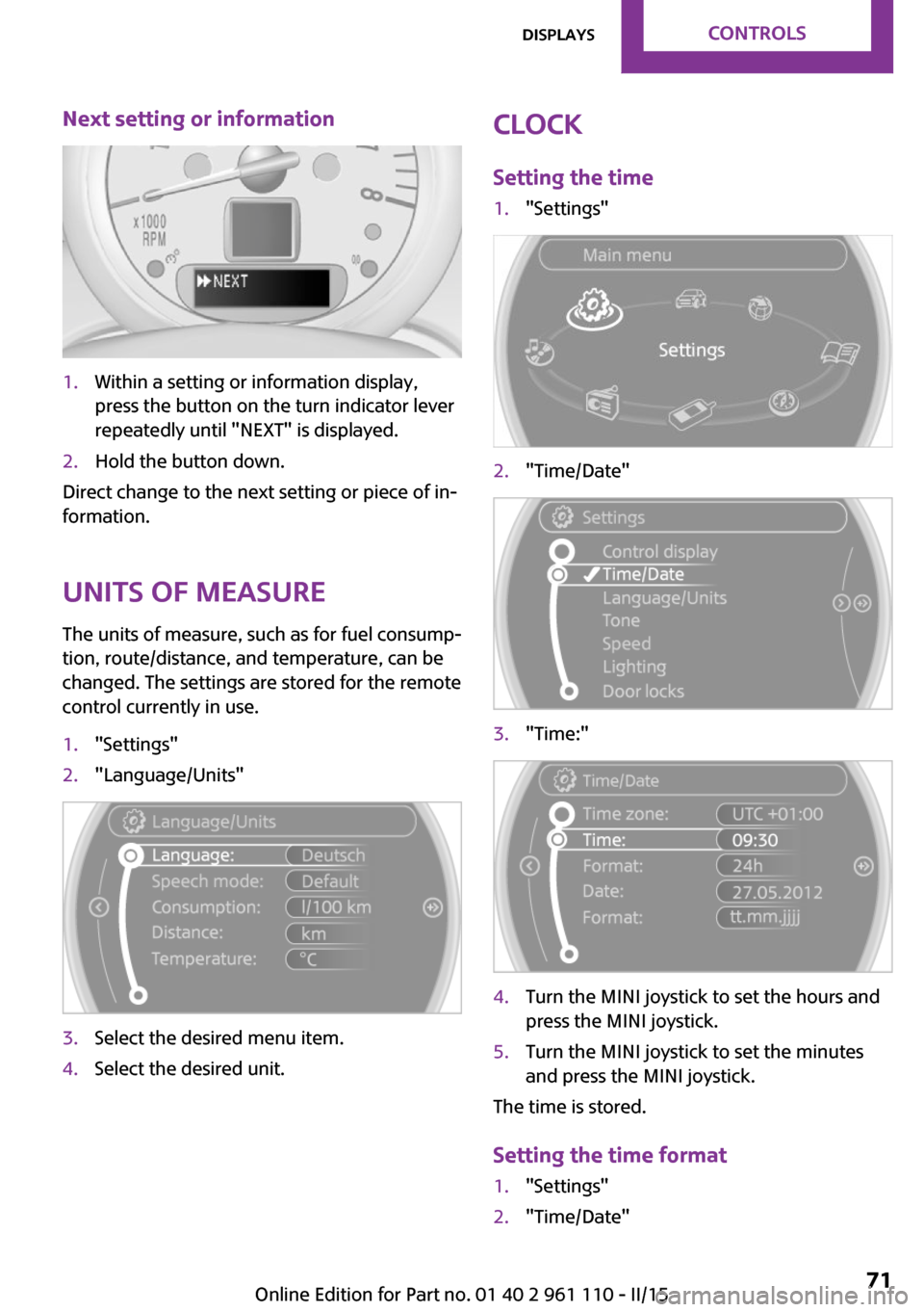
1."Settings"2."Language/Units"3.Select the desired menu item.4.Select the desired unit.Clock
Setting the time1."Settings"2."Time/Date"3."Time:"4.Turn the MINI joystick to set the hours and
press the MINI joystick.5.Turn the MINI joystick to set the minutes
and press the MINI joystick.
The time is stored.
Setting the time format
1."Settings"2."Time/Date"Seite 71DisplaysCONTROLS71
Online Edition for Part no. 01 40 2 961 110 - II/15
Page 82 of 283

▷Press the button briefly: the brightness
changes in stages.▷Press and hold the button: the brightness
changes continuously.
Interior lights
The interior lights, the footwell lights and thecargo area light are controlled automatically.
To avoid draining the battery, all lights inside
the vehicle are switched off some time after the
ignition is switched off.
Switching interior lights on/off
manually
To switch the interior lights on/off: press the
switch.
If the interior lights are to remain switched off,
press the switch for approx. 3 seconds.
Reading lights Reading lights are located in the front next to
the interior light and in the rear.
Switching the reading lights on/off
Front: press the switch.
Rear: press the button.
Ambient lighting
The color and brightness of the ambient light‐
ing can be changed.
Press the switch forward: the color changes in
steps.
Press the switch back: the brightness changes
in steps.
Intermediate settings and intermediate colors
are possible.
For continuously changing colors of the ambi‐
ent lighting, press the switch forward for more
than 10 seconds.
For Canadian vehicles:
Continuously changing colors of the ambient
lighting is not available.
Seite 80CONTROLSLamps80
Online Edition for Part no. 01 40 2 961 110 - II/15
Page 85 of 283

Leave feet in the footwell
Make sure that the front passenger keeps
his or her feet in the footwell; otherwise, the
front passenger airbags may not function prop‐
erly. ◀
Child restraint fixing system in the front
passenger seat
Before transporting a child on the front passen‐
ger seat, read the safety and operating instruc‐
tions under Transporting children safely, refer
to page 52.◀
Malfunction of the automatic deactivation system
When transporting older children and adults,
the front passenger airbags may be deactivated
in certain sitting positions. In this case, the indi‐
cator lamp for the front passenger airbags
lights up.
In this case, change the sitting position so that
the front passenger airbags are activated and
the indicator lamp goes out.
If it is not possible to activate the airbags, have
the person sit in the rear.
To make sure that occupation of the seat cush‐
ion can be detected correctly:▷Do not attach seat covers, seat cushion
padding, ball mats, or other items to the
front passenger seat unless they are specifi‐
cally recommended by the manufacturer of
your MINI.▷Do not place electronic devices on the pas‐
senger seat if a child restraint fixing system
is mounted on the seat.▷Do not place objects under the seat that
could press against the seat from below.Indicator light for the front passenger airbags
The indicator lamp for the front passenger air‐
bags indicates the operating state of the front
passenger airbags.
The light indicates whether the airbags are acti‐
vated or deactivated.
▷The indicator lamp lights up
when a child who is properly
seated in a child restraint fix‐
ing system intended for that
purpose is detected on the
seat or the seat is empty. The
airbags on the front passen‐
ger side are not activated.▷The indicator lamp does not light up when,
for example, a correctly seated person of
sufficient size is detected on the seat. The
airbags on the front passenger side are ac‐
tivated.
Most child seats are detected by the system.
Especially the child seats required by NHTSA at
the time that the vehicle was manufactured.
After installing a child seat, make sure that the
indicator lamp for the front passenger airbags
lights up. This indicates that the child seat has
been detected and the front passenger airbags
are not activated.
Seite 83SafetyCONTROLS83
Online Edition for Part no. 01 40 2 961 110 - II/15
Page 94 of 283

Driving stability control systemsVehicle equipment
This chapter describes all series equipment as
well as country-specific and special equipment
offered for this model series. Therefore, it also
describes equipment that may not be found in
your vehicle, for instance due to the selected
special equipment or the country version. This
also applies to safety-related functions and sys‐
tems.
When using the features and systems described
here, adhere to local regulations.
Antilock Brake System
ABS
ABS prevents locking of the wheels during braking.
Steerability is maintained even during full brak‐
ing. This increases active driving safety.
ABS is operational every time you start the en‐
gine.
Electronic brake-force distribution EBVThe system controls the brake pressure in the
rear wheels to ensure stable braking behavior.
CBC Cornering Brake Control
When braking in curves or during a lane
change, driving stability and steering response
are improved further.
Brake assistant When the brakes are applied rapidly, this sys‐
tem automatically produces the maximum
braking force boost. In this way, the system
helps keep the braking distance as short aspossible. This system utilizes all of the benefits
provided by ABS.
Do not reduce the pressure on the brake pedal
for the duration of full braking.
Dynamic Stability Con‐ trol DSC
The concept
DSC prevents traction loss in the driving wheels
when driving away and accelerating.
DSC also recognizes unstable vehicle condi‐
tions, such as fishtailing or nose-diving. Subject
to physical limits, DSC helps to keep the vehicle
on a steady course by reducing engine speed
and by applying brakes to the individual
wheels.
DSC is operational every time you start the en‐
gine.
Adjust your driving style to the situation
An appropriate driving style is always the
responsibility of the driver.
The laws of physics cannot be repealed, even
with DSC.
Do not reduce the additional safety margin
with a risky driving style, as otherwise there is a
risk of an accident. ◀Seite 92CONTROLSDriving stability control systems92
Online Edition for Part no. 01 40 2 961 110 - II/15
Page 108 of 283

3.Hold the hand-held transmitter of the sys‐
tem to be operated a distance of approx. 1
to 3 in/2.5 to 8 cm away from the buttons
on the interior rearview mirror. The re‐
quired distance depends on the particular
hand-held transmitter.4.Press the button of the desired function on
the hand-held transmitter and the button
being programmed on the interior rearview
mirror simultaneously and hold. The LED on
the interior rearview mirror flashes slowly at
first.5.When the LED flashes more rapidly, release
both buttons. Rapid flashing indicates that
the button on the interior rearview mirror
has been programmed.
If the LED does not flash faster after 60 sec‐
onds, change the distance between the in‐
terior rearview mirror and the hand-held
transmitter and repeat the step. Multiple
trials at different distances may be neces‐
sary. Wait at least 15 seconds between tri‐
als.6.To program additional functions on other
buttons, repeat steps 3 to 5.
The systems can be operated with the buttons
on the interior rearview mirror.
Special characteristics of alternating-
code radio systems
If the system cannot be operated after re‐
peated programming, check whether the sys‐
tem to be operated uses an alternating-code
system.
Read the operating instructions of the system
or press and hold the programmed button on
the interior rearview mirror. If the LED on the
interior rearview mirror flashes rapidly at first
and then lights up continuously for 2 seconds,
the system is equipped with an alternating-
code system. This flashing LED pattern repeats
itself for approx. 20 seconds.
In systems with an alternating-code system, the
universal garage door opener and the system
must be additionally synchronized.
Please obtain additional information on syn‐
chronization in the operating instructions of the
system being set up.
The systems will be easier to synchronize with
the aid of a second person.
Synchronization:1.Park the vehicle within range of the re‐
mote-controlled system.2.Program the corresponding button on the
interior rearview mirror as described.3.Identify and press the synchronization but‐
ton on the system being set up. You have
approx. 30 seconds for the next step.4.Press and hold the button on the interior
rearview mirror for approx. 3 seconds and
then release it. Repeat this step up to three
times if necessary to complete the synchro‐
nization procedure. When synchronization
is completed, the programmed function is
executed.
Reprogramming individual buttons
1.Switch on the ignition.2.Hold the hand-held transmitter at a dis‐
tance of approx. 1 to 3 in/2.5 to 8 cm from
the memory buttons.
The required distance depends on the par‐
ticular hand-held transmitter.3.Press the memory button of the universal
garage door opener.4.If the LED flashes slowly after approx.
20 seconds, press the transmit button on
the hand-held transmitter.5.Release both buttons when the LED flashes
rapidly.
If the LED does not flash rapidly after ap‐
prox. 60 seconds, change the distance and
repeat the step.Seite 106CONTROLSInterior equipment106
Online Edition for Part no. 01 40 2 961 110 - II/15
Page 109 of 283

Canada: if the LED does not flash rapidly af‐
ter approx. 60 seconds, change the dis‐
tance and repeat the step. If programming
was aborted by the hand-held transmitter,
hold down the memory button and press
and release the button on the hand-held
transmitter several times for 2 seconds.
Controls
Prior to operation
Before operating a unit with the Universal
Garage Door Opener, ensure that there are no
people, animals, or objects in the range of
movement of the system; otherwise, there is a
risk of injury or damage.
Also follow the safety instructions of the hand-
held transmitter. ◀
The system, such as the garage door, can be
operated using the button on the interior rear‐
view mirror with the engine running or the igni‐
tion switched on. When you are within the re‐
ception range of the system, press and hold the
button until the function is initiated. The LED on
the interior rearview mirror lights up continu‐
ously while the radio signal is being transmit‐
ted.
Deleting stored functions
Press the right and left buttons on the interior
rearview mirror simultaneously for approx.
20 seconds until the LED flashes rapidly. All
stored functions are deleted. The functions can‐
not be deleted individually.
Sun visor Glare protection
Folding down
Fold the sun visor down.
Folding up
Fold the sun visor up.
Glare protection from the side
Folding down1.Fold the sun visor down.2.Detach from the holder and pivot sideways
to the side window.
Folding up
To close the sun visor, proceed in reverse order.
Vanity mirror A vanity mirror is located behind a cover on
each sun visor.
To open, fold the cover up.
Depending on the vehicle equipment, mirror
lighting comes on when the cover is opened.
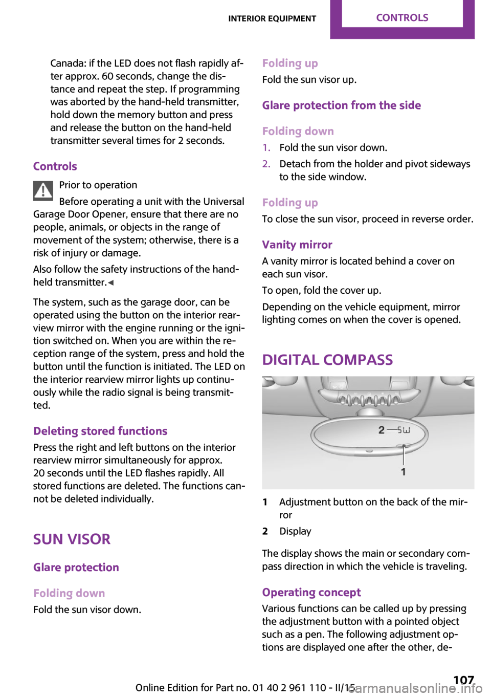
Digital compass
1Adjustment button on the back of the mir‐
ror2Display
The display shows the main or secondary com‐
pass direction in which the vehicle is traveling.
Operating concept
Various functions can be called up by pressing
the adjustment button with a pointed object
such as a pen. The following adjustment op‐
tions are displayed one after the other, de‐
Seite 107Interior equipmentCONTROLS107
Online Edition for Part no. 01 40 2 961 110 - II/15
Page 145 of 283

Destination guidanceVehicle equipmentThis chapter describes all series equipment as
well as country-specific and special equipment
offered for this model series. Therefore, it also
describes equipment that may not be found in
your vehicle, for instance due to the selected
special equipment or the country version. This
also applies to safety-related functions and sys‐
tems.
When using the features and systems described
here, adhere to local regulations.
Starting destination
guidance1."Navigation"2.Make a destination entry, refer to
page 134.3."Accept destination"4."Start guidance"
The route is shown on the Control Display.
The distance to the destination/intermediate
destination and the estimated time of arrival
are displayed in the map view.
The arrow view may appear on the Control Dis‐
play.
Terminating destination
guidance
1."Navigation"2."Map"3. Select the symbol.4."Stop guidance"Continuing destination
guidance
If the destination was not reached during the
last trip, destination guidance can be resumed.
"Resume guidance"
Route criteria
General information▷The route calculated can be influenced by
selecting certain criteria.▷The route criteria can be changed when the
destination is entered and during destina‐
tion guidance.▷Road types are part of the navigation data
and are taken into consideration when
planning a route, e.g., avoid highways.▷The recommended route may differ from
the route you would take based on per‐
sonal experience.▷The settings are stored for the remote con‐
trol currently in use.▷Destination guidance with traffic bulletins,
refer to page 149.
Changing the route criteria
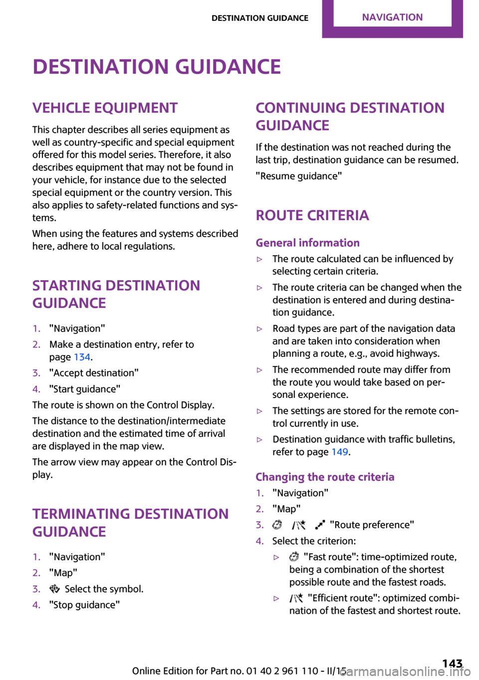
1."Navigation"2."Map"3. "Route preference"4.Select the criterion:▷ "Fast route": time-optimized route,
being a combination of the shortest
possible route and the fastest roads.▷ "Efficient route": optimized combi‐
nation of the fastest and shortest route.Seite 143Destination guidanceNAVIGATION143
Online Edition for Part no. 01 40 2 961 110 - II/15