radio controls MINI Countryman 2015 Owner's Manual (Mini Connected)
[x] Cancel search | Manufacturer: MINI, Model Year: 2015, Model line: Countryman, Model: MINI Countryman 2015Pages: 283, PDF Size: 6.76 MB
Page 7 of 283
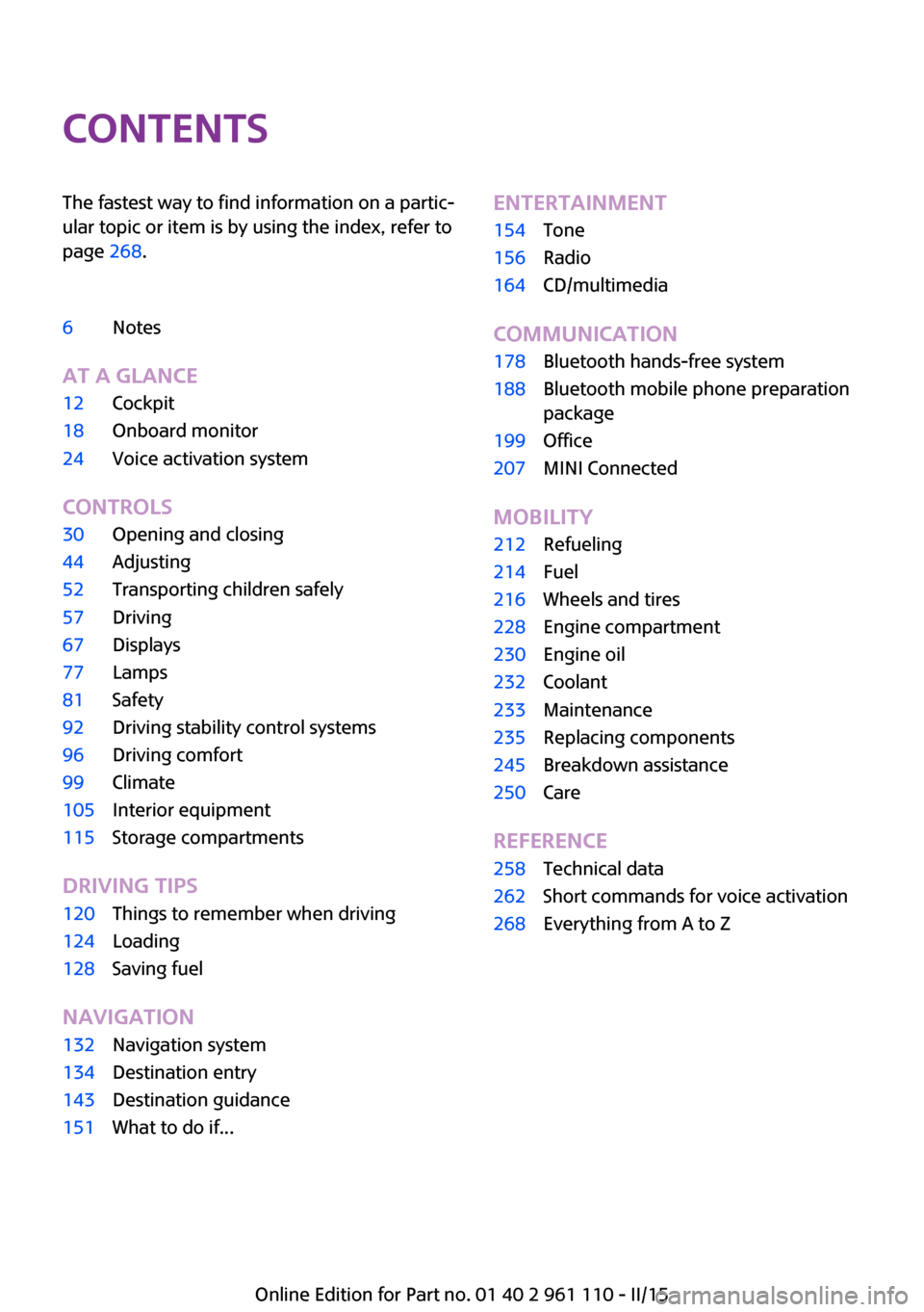
ContentsThe fastest way to find information on a partic‐
ular topic or item is by using the index, refer to
page 268.6Notes
AT A GLANCE
12Cockpit18Onboard monitor24Voice activation system
CONTROLS
30Opening and closing44Adjusting52Transporting children safely57Driving67Displays77Lamps81Safety92Driving stability control systems96Driving comfort99Climate105Interior equipment115Storage compartments
DRIVING TIPS
120Things to remember when driving124Loading128Saving fuel
NAVIGATION
132Navigation system134Destination entry143Destination guidance151What to do if...ENTERTAINMENT154Tone156Radio164CD/multimedia
COMMUNICATION
178Bluetooth hands-free system188Bluetooth mobile phone preparation
package199Office207MINI Connected
MOBILITY
212Refueling214Fuel216Wheels and tires228Engine compartment230Engine oil232Coolant233Maintenance235Replacing components245Breakdown assistance250Care
REFERENCE
258Technical data262Short commands for voice activation268Everything from A to Z
Online Edition for Part no. 01 40 2 961 110 - II/15
Page 35 of 283
Convenient closing with the remote control is
not possible.
Locking
Press the button.
Locking from the outside
Do not lock the vehicle from the outside if
there are people in it, as the vehicle cannot be
unlocked from inside without special knowl‐
edge. ◀
Setting the confirmation signals
Have unlocking or locking of the vehicle con‐
firmed.
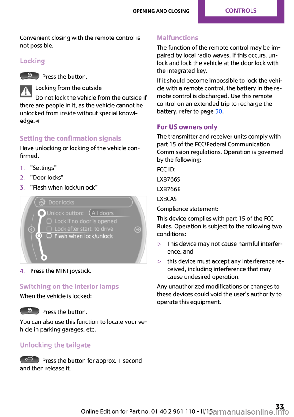
1."Settings"2."Door locks"3."Flash when lock/unlock"4.Press the MINI joystick.
Switching on the interior lamps
When the vehicle is locked:
Press the button.
You can also use this function to locate your ve‐
hicle in parking garages, etc.
Unlocking the tailgate
Press the button for approx. 1 second
and then release it.
Malfunctions
The function of the remote control may be im‐
paired by local radio waves. If this occurs, un‐ lock and lock the vehicle at the door lock with
the integrated key.
If it should become impossible to lock the vehi‐
cle with a remote control, the battery in the re‐
mote control is discharged. Use this remote control on an extended trip to recharge the
battery, refer to page 30.
For US owners only The transmitter and receiver units comply with
part 15 of the FCC/Federal Communication
Commission regulations. Operation is governed
by the following:
FCC ID:
LX8766S
LX8766E
LX8CAS
Compliance statement:
This device complies with part 15 of the FCC
Rules. Operation is subject to the following two
conditions:▷This device may not cause harmful interfer‐
ence, and▷this device must accept any interference re‐
ceived, including interference that may
cause undesired operation.
Any unauthorized modifications or changes to
these devices could void the user's authority to
operate this equipment.
Seite 33Opening and closingCONTROLS33
Online Edition for Part no. 01 40 2 961 110 - II/15
Page 40 of 283
If a remote control accidentally left in the cargo
area is detected in the locked vehicle after the
tailgate is closed, the tailgate opens again
slightly. The hazard warning system flashes and
an acoustic signal sounds.
Power windows and electrical glass
sunroof
When the engine is switched off, the windows
and the sunroof can be operated as long as
neither the doors nor the tailgate are opened.
When the door and tailgate are closed again
and the remote control is detected inside the
vehicle, the windows and the sunroof can be
operated again.
Insert the remote control into the ignition lock
to be able to operate the windows and the sun‐
roof while the engine is switched off and the
doors are open.
Switching on the radio ready state Press the Start/Stop button to switch on the
radio ready state, refer to page 57.
Do not depress the brake or the clutch; other‐
wise, the engine will start.
Starting the engine The engine can be started or the ignition can
be switched on, refer to page 57, when a re‐
mote control is inside the vehicle. It is not nec‐
essary to insert a remote control into the igni‐
tion lock.
Switching off the engine in cars with
Steptronic transmission
The engine can only be switched off with the
selector lever in position P, refer to page 64.
To switch off the engine with the selector lever
in position N, the remote control must be in‐
serted in the ignition lock.Before driving a vehicle with Steptronic
transmission into a car wash1.Insert the remote control into the ignition
switch.2.Depress the brake pedal.3.Move the selector lever to position N.4.Switch the engine off.
The vehicle can roll.
Malfunction The Comfort Access functions can be disturbed
by local radio waves, such as by a mobile
phone in the immediate vicinity of the remote
control or when a mobile phone is being
charged in the vehicle.
If this occurs, open or close the vehicle using
the buttons on the remote control or use the
integrated key in the door lock.
To start the engine afterward, insert the remote
control into the ignition switch.
Warning lights The warning light in the instrument
cluster lights up when you attempt to
start the engine: the engine cannot be
started.
The remote control is not in the vehicle or has a
malfunction. Take the remote control with you
inside the vehicle or have it checked. If neces‐
sary, insert another remote control into the ig‐
nition switch.
The warning lamp in the instrument
cluster lights up while the engine is run‐
ning: the remote control is no longer in‐
side the vehicle.
After switching off the engine, the engine can
only be started again within approx. 10 sec‐
onds if no door has been opened.
The indicator lamp lights up and a mes‐
sage appears on the Control Display: re‐
place the remote control battery.
Seite 38CONTROLSOpening and closing38
Online Edition for Part no. 01 40 2 961 110 - II/15
Page 44 of 283
Take the remote control with you
Take the remote control with you when
leaving the vehicle so that children, for exam‐
ple, cannot operate the power windows and in‐
jure themselves. ◀
If, after having been opened and closed a num‐
ber of times in close succession, a window can
only be closed, the system is overheated. Let
the system cool down for several minutes with
the ignition switched on or the engine running.
Opening, closing
Front windows
To open:
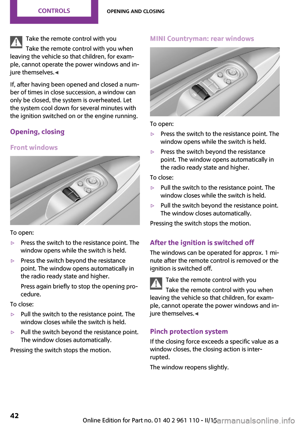
▷Press the switch to the resistance point. The
window opens while the switch is held.▷Press the switch beyond the resistance
point. The window opens automatically in
the radio ready state and higher.
Press again briefly to stop the opening pro‐
cedure.
To close:
▷Pull the switch to the resistance point. The
window closes while the switch is held.▷Pull the switch beyond the resistance point.
The window closes automatically.
Pressing the switch stops the motion.
MINI Countryman: rear windows
To open:
▷Press the switch to the resistance point. The
window opens while the switch is held.▷Press the switch beyond the resistance
point. The window opens automatically in
the radio ready state and higher.
To close:
▷Pull the switch to the resistance point. The
window closes while the switch is held.▷Pull the switch beyond the resistance point.
The window closes automatically.
Pressing the switch stops the motion.
After the ignition is switched off
The windows can be operated for approx. 1 mi‐
nute after the remote control is removed or the
ignition is switched off.
Take the remote control with you
Take the remote control with you when
leaving the vehicle so that children, for exam‐
ple, cannot operate the power windows and in‐
jure themselves. ◀
Pinch protection system If the closing force exceeds a specific value as a
window closes, the closing action is inter‐
rupted.
The window reopens slightly.
Seite 42CONTROLSOpening and closing42
Online Edition for Part no. 01 40 2 961 110 - II/15
Page 59 of 283
DrivingVehicle equipmentThis chapter describes all series equipment as
well as country-specific and special equipment
offered for this model series. Therefore, it also
describes equipment that may not be found in
your vehicle, for instance due to the selected
special equipment or the country version. This
also applies to safety-related functions and sys‐
tems.
When using the features and systems described
here, adhere to local regulations.
Ignition lock
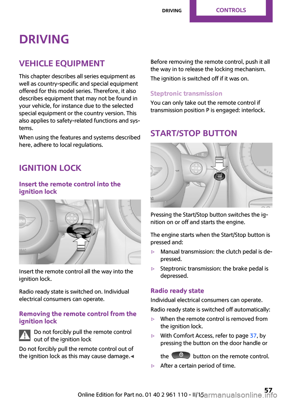
Insert the remote control into the
ignition lock
Insert the remote control all the way into the
ignition lock.
Radio ready state is switched on. Individual
electrical consumers can operate.
Removing the remote control from the
ignition lock
Do not forcibly pull the remote control
out of the ignition lock
Do not forcibly pull the remote control out of
the ignition lock as this may cause damage. ◀
Before removing the remote control, push it all
the way in to release the locking mechanism.
The ignition is switched off if it was on.
Steptronic transmission You can only take out the remote control if
transmission position P is engaged: interlock.
Start/Stop button
Pressing the Start/Stop button switches the ig‐
nition on or off and starts the engine.
The engine starts when the Start/Stop button is
pressed and:
▷Manual transmission: the clutch pedal is de‐
pressed.▷Steptronic transmission: the brake pedal is
depressed.
Radio ready state
Individual electrical consumers can operate.
Radio ready state is switched off automatically:
▷When the remote control is removed from
the ignition lock.▷With Comfort Access, refer to page 37, by
pressing the button on the door handle or
the
button on the remote control.
▷After a certain period of time.Seite 57DrivingCONTROLS57
Online Edition for Part no. 01 40 2 961 110 - II/15
Page 60 of 283
Ignition onAll electrical consumers can operate. Most indi‐
cator and warning lights light up for different
lengths of time.
To save battery power when the engine is off,
switch off the ignition and any unnecessary electronic systems/power consumers.
Radio ready state and ignition off All indicator and warning lights in the displays
go out.
The ignition switches off automatically when
the driver's door is opened. Pressing the Start/
Stop button again switches the ignition back
on.
For example, the ignition is not switched off in
the following situations:▷Depress the clutch or brake pedal.▷The low beams are switched on.
Starting the engine
General information Enclosed areas
Do not let the engine run in enclosed
areas; otherwise, breathing of exhaust fumes
may lead to loss of consciousness and death.
The exhaust gases contain carbon monoxide,
an odorless and colorless but highly toxic gas. ◀
Unattended vehicle
Do not leave the car unattended with the
engine running; otherwise, it presents a poten‐
tial source of danger.
Before leaving the car with the engine running,
shift to neutral or engage transmission posi‐
tion P and set the parking brake firmly; other‐ wise, the vehicle may begin to roll. ◀
Frequent starting in quick succession
Avoid repeated futile attempts at starting
the car and avoid starting the car frequently in
quick succession. Otherwise, the fuel is not
burned or is inadequately burned, and there is
the danger of overheating and damaging the
catalytic converter. ◀
Do not wait for the engine to warm-up while
the vehicle remains stationary; start driving
right away, but at moderate engine speeds.
Do not depress the accelerator when starting
the engine.
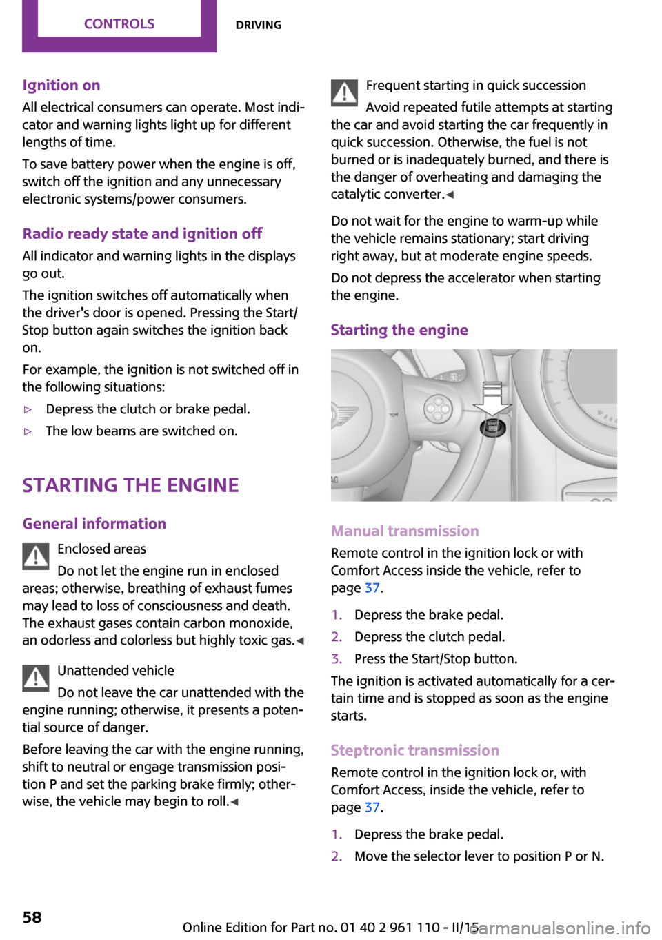
Starting the engine
Manual transmission
Remote control in the ignition lock or with
Comfort Access inside the vehicle, refer to
page 37.
1.Depress the brake pedal.2.Depress the clutch pedal.3.Press the Start/Stop button.
The ignition is activated automatically for a cer‐
tain time and is stopped as soon as the engine
starts.
Steptronic transmission
Remote control in the ignition lock or, with
Comfort Access, inside the vehicle, refer to
page 37.
1.Depress the brake pedal.2.Move the selector lever to position P or N.Seite 58CONTROLSDriving58
Online Edition for Part no. 01 40 2 961 110 - II/15
Page 86 of 283
Operational readiness of airbag system
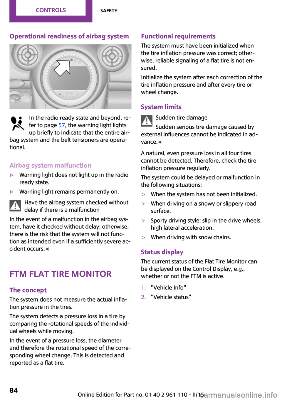
In the radio ready state and beyond, re‐
fer to page 57, the warning light lights
up briefly to indicate that the entire air‐
bag system and the belt tensioners are opera‐
tional.
Airbag system malfunction
▷Warning light does not light up in the radio
ready state.▷Warning light remains permanently on.
Have the airbag system checked without
delay if there is a malfunction
In the event of a malfunction in the airbag sys‐
tem, have it checked without delay; otherwise,
there is the risk that the system will not func‐
tion as intended even if a sufficiently severe ac‐
cident occurs. ◀
FTM Flat Tire Monitor The concept
The system does not measure the actual infla‐
tion pressure in the tires.
The system detects a pressure loss in a tire by
comparing the rotational speeds of the individ‐
ual wheels while moving.
In the event of a pressure loss, the diameter
and therefore the rotational speed of the corre‐
sponding wheel change. This is detected and
reported as a flat tire.
Functional requirements
The system must have been initialized when
the tire inflation pressure was correct; other‐
wise, reliable signaling of a flat tire is not en‐
sured.
Initialize the system after each correction of the
tire inflation pressure and after every tire or
wheel change.
System limits Sudden tire damage
Sudden serious tire damage caused by
external influences cannot be indicated in ad‐
vance. ◀
A natural, even pressure loss in all four tires
cannot be detected. Therefore, check the tire
inflation pressure regularly.
The system could be delayed or malfunction in
the following situations:▷When the system has not been initialized.▷When driving on a snowy or slippery road
surface.▷Sporty driving style: slip in the drive wheels,
high lateral acceleration.▷When driving with snow chains.
Status display
The current status of the Flat Tire Monitor can
be displayed on the Control Display, e.g.,
whether or not the FTM is active.
1."Vehicle Info"2."Vehicle status"Seite 84CONTROLSSafety84
Online Edition for Part no. 01 40 2 961 110 - II/15
Page 91 of 283

Continued driving with a flat tire
Drive moderately and do not exceed a
speed of 50 mph/80 km/h.
A loss of tire inflation pressure results in a
change in the handling characteristics, e.g., re‐
duced lane stability during braking, a longer
braking distance and altered self-steering prop‐
erties. ◀
Final tire failure
Vibrations or loud noises while driving
can indicate the final failure of the tire. Reduce
speed and stop; otherwise, pieces of the tire
could come loose and cause an accident. Do
not continue driving, and contact your service
center. ◀
Message indicating that the inflation
pressure needs to be checked
The yellow warning light lights up.
A Check Control message is displayed.
An additional message is displayed on
the onboard monitor.▷The system has detected that a wheel was
changed but a reset was not performed.▷The tire was not inflated according to speci‐
fications.▷The tire pressure has dropped since the last
confirmation.
In this case:
▷Check the tire inflation pressure and correct
it if necessary.▷After changing a wheel, reset the system.
System limits
The system will not function properly if a reset
was not performed, e.g., it may identify a tire as
flat although the tire is filled to the correct infla‐
tion pressure.
The tire pressure depends on the temperature
of the tire. An increase in the tire temperature,
e.g., while driving or due to sunlight, increases
the tire inflation pressure. The tire pressure de‐
creases when the tire temperature drops. In
case of severe temperature drops, this behavior
may lead to a warning on account of the de‐
fined warning limits.
Malfunction The yellow warning light flashes yellow
and then lights up continuously.
A Check Control message is displayed.
An additional message is displayed on
the onboard monitor.
A flat tire or tire inflation pressure loss cannot
be detected.
Display in the following situations:▷A wheel without TPM electronics is
mounted, e.g., a compact wheel:
Have the system checked by the service
center if necessary.▷Malfunction:
Have the system checked by the service
center.▷TPM was unable to complete the reset.
Reset the system again.
The yellow warning light flashes and
then lights up continuously.
A Check Control message is displayed.
An additional message is displayed on
the onboard monitor.
A flat tire or tire inflation pressure loss cannot
be detected.
Display in the following situation:
▷Disturbance by other systems or devices
with the same radio frequency:
After leaving the area of the disturbance,
the system automatically becomes active
again.Seite 89SafetyCONTROLS89
Online Edition for Part no. 01 40 2 961 110 - II/15
Page 108 of 283

3.Hold the hand-held transmitter of the sys‐
tem to be operated a distance of approx. 1
to 3 in/2.5 to 8 cm away from the buttons
on the interior rearview mirror. The re‐
quired distance depends on the particular
hand-held transmitter.4.Press the button of the desired function on
the hand-held transmitter and the button
being programmed on the interior rearview
mirror simultaneously and hold. The LED on
the interior rearview mirror flashes slowly at
first.5.When the LED flashes more rapidly, release
both buttons. Rapid flashing indicates that
the button on the interior rearview mirror
has been programmed.
If the LED does not flash faster after 60 sec‐
onds, change the distance between the in‐
terior rearview mirror and the hand-held
transmitter and repeat the step. Multiple
trials at different distances may be neces‐
sary. Wait at least 15 seconds between tri‐
als.6.To program additional functions on other
buttons, repeat steps 3 to 5.
The systems can be operated with the buttons
on the interior rearview mirror.
Special characteristics of alternating-
code radio systems
If the system cannot be operated after re‐
peated programming, check whether the sys‐
tem to be operated uses an alternating-code
system.
Read the operating instructions of the system
or press and hold the programmed button on
the interior rearview mirror. If the LED on the
interior rearview mirror flashes rapidly at first
and then lights up continuously for 2 seconds,
the system is equipped with an alternating-
code system. This flashing LED pattern repeats
itself for approx. 20 seconds.
In systems with an alternating-code system, the
universal garage door opener and the system
must be additionally synchronized.
Please obtain additional information on syn‐
chronization in the operating instructions of the
system being set up.
The systems will be easier to synchronize with
the aid of a second person.
Synchronization:1.Park the vehicle within range of the re‐
mote-controlled system.2.Program the corresponding button on the
interior rearview mirror as described.3.Identify and press the synchronization but‐
ton on the system being set up. You have
approx. 30 seconds for the next step.4.Press and hold the button on the interior
rearview mirror for approx. 3 seconds and
then release it. Repeat this step up to three
times if necessary to complete the synchro‐
nization procedure. When synchronization
is completed, the programmed function is
executed.
Reprogramming individual buttons
1.Switch on the ignition.2.Hold the hand-held transmitter at a dis‐
tance of approx. 1 to 3 in/2.5 to 8 cm from
the memory buttons.
The required distance depends on the par‐
ticular hand-held transmitter.3.Press the memory button of the universal
garage door opener.4.If the LED flashes slowly after approx.
20 seconds, press the transmit button on
the hand-held transmitter.5.Release both buttons when the LED flashes
rapidly.
If the LED does not flash rapidly after ap‐
prox. 60 seconds, change the distance and
repeat the step.Seite 106CONTROLSInterior equipment106
Online Edition for Part no. 01 40 2 961 110 - II/15
Page 109 of 283
Canada: if the LED does not flash rapidly af‐
ter approx. 60 seconds, change the dis‐
tance and repeat the step. If programming
was aborted by the hand-held transmitter,
hold down the memory button and press
and release the button on the hand-held
transmitter several times for 2 seconds.
Controls
Prior to operation
Before operating a unit with the Universal
Garage Door Opener, ensure that there are no
people, animals, or objects in the range of
movement of the system; otherwise, there is a
risk of injury or damage.
Also follow the safety instructions of the hand-
held transmitter. ◀
The system, such as the garage door, can be
operated using the button on the interior rear‐
view mirror with the engine running or the igni‐
tion switched on. When you are within the re‐
ception range of the system, press and hold the
button until the function is initiated. The LED on
the interior rearview mirror lights up continu‐
ously while the radio signal is being transmit‐
ted.
Deleting stored functions
Press the right and left buttons on the interior
rearview mirror simultaneously for approx.
20 seconds until the LED flashes rapidly. All
stored functions are deleted. The functions can‐
not be deleted individually.
Sun visor Glare protection
Folding down
Fold the sun visor down.
Folding up
Fold the sun visor up.
Glare protection from the side
Folding down1.Fold the sun visor down.2.Detach from the holder and pivot sideways
to the side window.
Folding up
To close the sun visor, proceed in reverse order.
Vanity mirror A vanity mirror is located behind a cover on
each sun visor.
To open, fold the cover up.
Depending on the vehicle equipment, mirror
lighting comes on when the cover is opened.
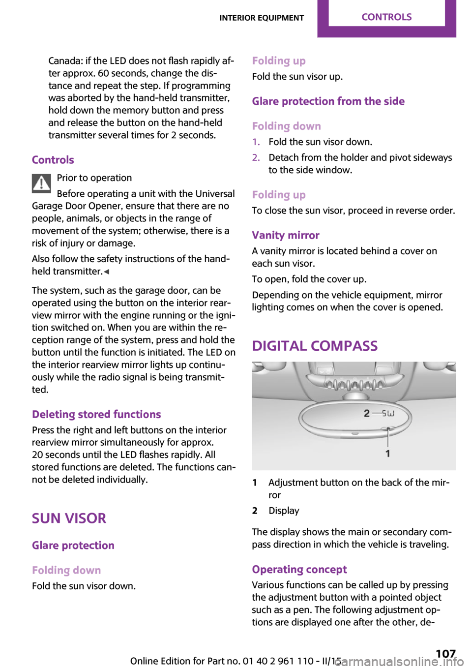
Digital compass
1Adjustment button on the back of the mir‐
ror2Display
The display shows the main or secondary com‐
pass direction in which the vehicle is traveling.
Operating concept
Various functions can be called up by pressing
the adjustment button with a pointed object
such as a pen. The following adjustment op‐
tions are displayed one after the other, de‐
Seite 107Interior equipmentCONTROLS107
Online Edition for Part no. 01 40 2 961 110 - II/15