turn signal MINI Countryman 2015 Owner's Manual (Mini Connected)
[x] Cancel search | Manufacturer: MINI, Model Year: 2015, Model line: Countryman, Model: MINI Countryman 2015Pages: 283, PDF Size: 6.76 MB
Page 14 of 283
CockpitVehicle equipment
This chapter describes all series equipment as
well as country-specific and special equipment
offered for this model series. Therefore, it also
describes equipment that may not be found in
your vehicle, for instance due to the selectedspecial equipment or the country version. This
also applies to safety-related functions and sys‐
tems.
When using the features and systems described
here, adhere to local regulations.
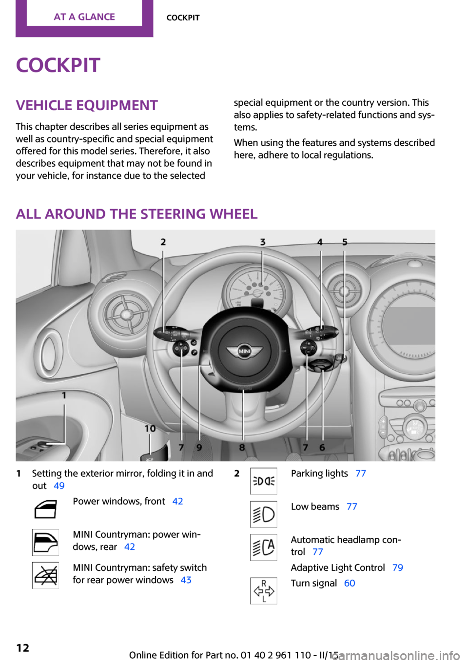
All around the steering wheel
1Setting the exterior mirror, folding it in and
out 49Power windows, front 42MINI Countryman: power win‐
dows, rear 42MINI Countryman: safety switch
for rear power windows 432Parking lights 77Low beams 77Automatic headlamp con‐
trol 77
Adaptive Light Control 79Turn signal 60Seite 12AT A GLANCECockpit12
Online Edition for Part no. 01 40 2 961 110 - II/15
Page 17 of 283
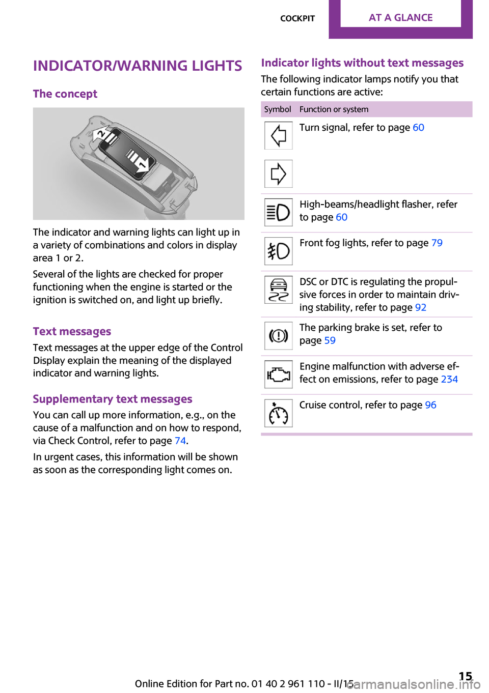
Indicator/warning lights
The concept
The indicator and warning lights can light up in
a variety of combinations and colors in display
area 1 or 2.
Several of the lights are checked for proper
functioning when the engine is started or the
ignition is switched on, and light up briefly.
Text messages
Text messages at the upper edge of the Control
Display explain the meaning of the displayed
indicator and warning lights.
Supplementary text messages
You can call up more information, e.g., on the
cause of a malfunction and on how to respond,
via Check Control, refer to page 74.
In urgent cases, this information will be shown
as soon as the corresponding light comes on.
Indicator lights without text messages
The following indicator lamps notify you that
certain functions are active:SymbolFunction or systemTurn signal, refer to page 60High-beams/headlight flasher, refer
to page 60Front fog lights, refer to page 79DSC or DTC is regulating the propul‐
sive forces in order to maintain driv‐
ing stability, refer to page 92The parking brake is set, refer to
page 59Engine malfunction with adverse ef‐
fect on emissions, refer to page 234Cruise control, refer to page 96Seite 15CockpitAT A GLANCE15
Online Edition for Part no. 01 40 2 961 110 - II/15
Page 33 of 283
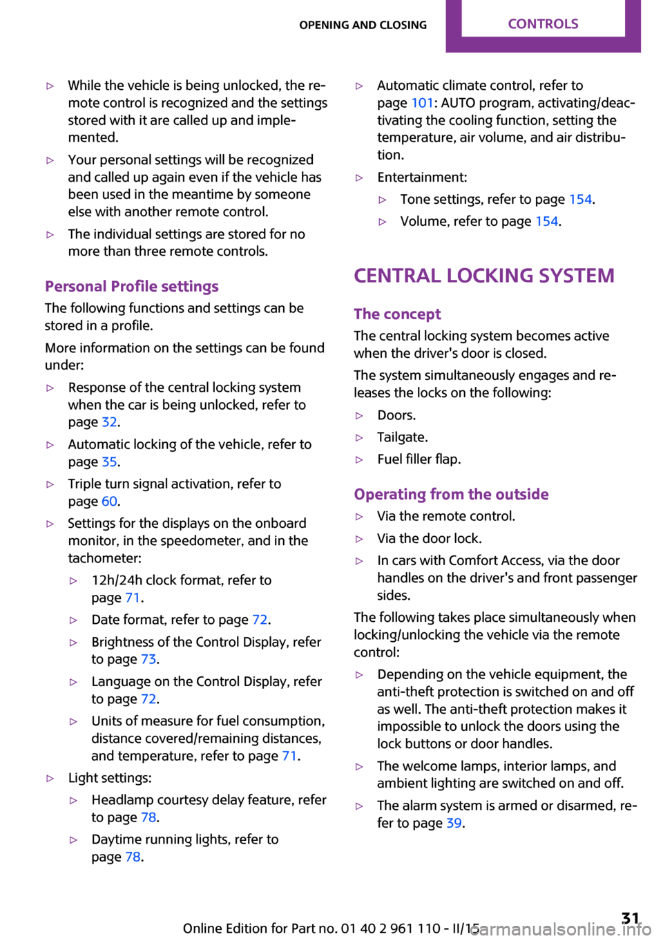
▷While the vehicle is being unlocked, the re‐
mote control is recognized and the settings
stored with it are called up and imple‐
mented.▷Your personal settings will be recognized
and called up again even if the vehicle has
been used in the meantime by someone
else with another remote control.▷The individual settings are stored for no
more than three remote controls.
Personal Profile settings
The following functions and settings can be
stored in a profile.
More information on the settings can be found
under:
▷Response of the central locking system
when the car is being unlocked, refer to
page 32.▷Automatic locking of the vehicle, refer to
page 35.▷Triple turn signal activation, refer to
page 60.▷Settings for the displays on the onboard
monitor, in the speedometer, and in the
tachometer:▷12h/24h clock format, refer to
page 71.▷Date format, refer to page 72.▷Brightness of the Control Display, refer
to page 73.▷Language on the Control Display, refer
to page 72.▷Units of measure for fuel consumption,
distance covered/remaining distances,
and temperature, refer to page 71.▷Light settings:▷Headlamp courtesy delay feature, refer
to page 78.▷Daytime running lights, refer to
page 78.▷Automatic climate control, refer to
page 101: AUTO program, activating/deac‐
tivating the cooling function, setting the
temperature, air volume, and air distribu‐
tion.▷Entertainment:▷Tone settings, refer to page 154.▷Volume, refer to page 154.
Central locking system
The concept
The central locking system becomes active
when the driver's door is closed.
The system simultaneously engages and re‐
leases the locks on the following:
▷Doors.▷Tailgate.▷Fuel filler flap.
Operating from the outside
▷Via the remote control.▷Via the door lock.▷In cars with Comfort Access, via the door
handles on the driver's and front passenger
sides.
The following takes place simultaneously when
locking/unlocking the vehicle via the remote
control:
▷Depending on the vehicle equipment, the
anti-theft protection is switched on and off
as well. The anti-theft protection makes it
impossible to unlock the doors using the
lock buttons or door handles.▷The welcome lamps, interior lamps, and
ambient lighting are switched on and off.▷The alarm system is armed or disarmed, re‐
fer to page 39.Seite 31Opening and closingCONTROLS31
Online Edition for Part no. 01 40 2 961 110 - II/15
Page 41 of 283
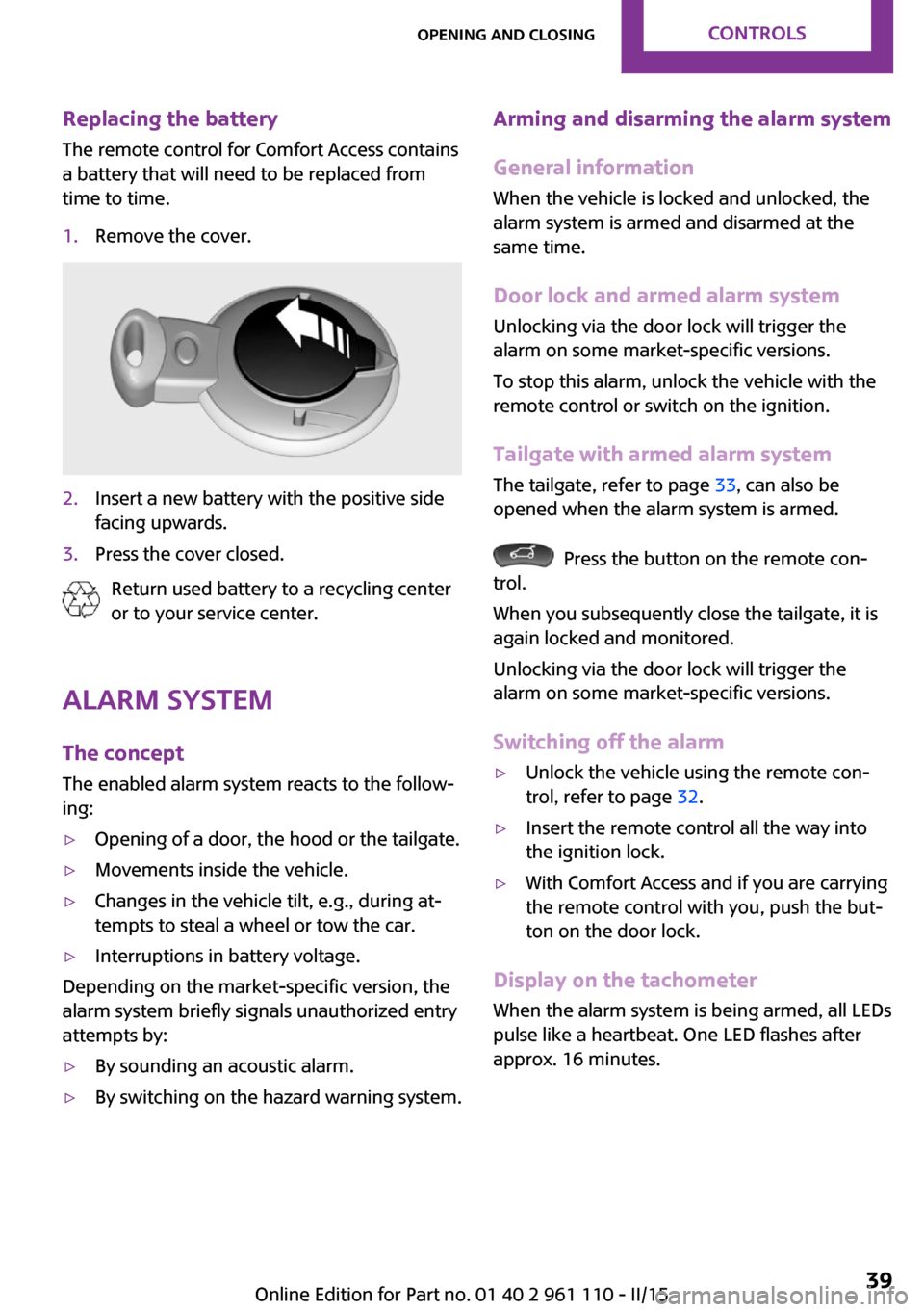
Replacing the battery
The remote control for Comfort Access contains
a battery that will need to be replaced from
time to time.1.Remove the cover.2.Insert a new battery with the positive side
facing upwards.3.Press the cover closed.
Return used battery to a recycling center
or to your service center.
Alarm system
The concept
The enabled alarm system reacts to the follow‐
ing:
▷Opening of a door, the hood or the tailgate.▷Movements inside the vehicle.▷Changes in the vehicle tilt, e.g., during at‐
tempts to steal a wheel or tow the car.▷Interruptions in battery voltage.
Depending on the market-specific version, the
alarm system briefly signals unauthorized entry
attempts by:
▷By sounding an acoustic alarm.▷By switching on the hazard warning system.Arming and disarming the alarm system
General information
When the vehicle is locked and unlocked, the
alarm system is armed and disarmed at the
same time.
Door lock and armed alarm systemUnlocking via the door lock will trigger the
alarm on some market-specific versions.
To stop this alarm, unlock the vehicle with the
remote control or switch on the ignition.
Tailgate with armed alarm system The tailgate, refer to page 33, can also be
opened when the alarm system is armed.
Press the button on the remote con‐
trol.
When you subsequently close the tailgate, it is
again locked and monitored.
Unlocking via the door lock will trigger the
alarm on some market-specific versions.
Switching off the alarm
▷Unlock the vehicle using the remote con‐
trol, refer to page 32.▷Insert the remote control all the way into
the ignition lock.▷With Comfort Access and if you are carrying
the remote control with you, push the but‐
ton on the door lock.
Display on the tachometer
When the alarm system is being armed, all LEDs
pulse like a heartbeat. One LED flashes after
approx. 16 minutes.
Seite 39Opening and closingCONTROLS39
Online Edition for Part no. 01 40 2 961 110 - II/15
Page 62 of 283
Excessive application of the parking brake can
block the rear wheels and lead to fishtailing of
the vehicle. ◀
The brake lights do not light up when the park‐
ing brake is pulled.
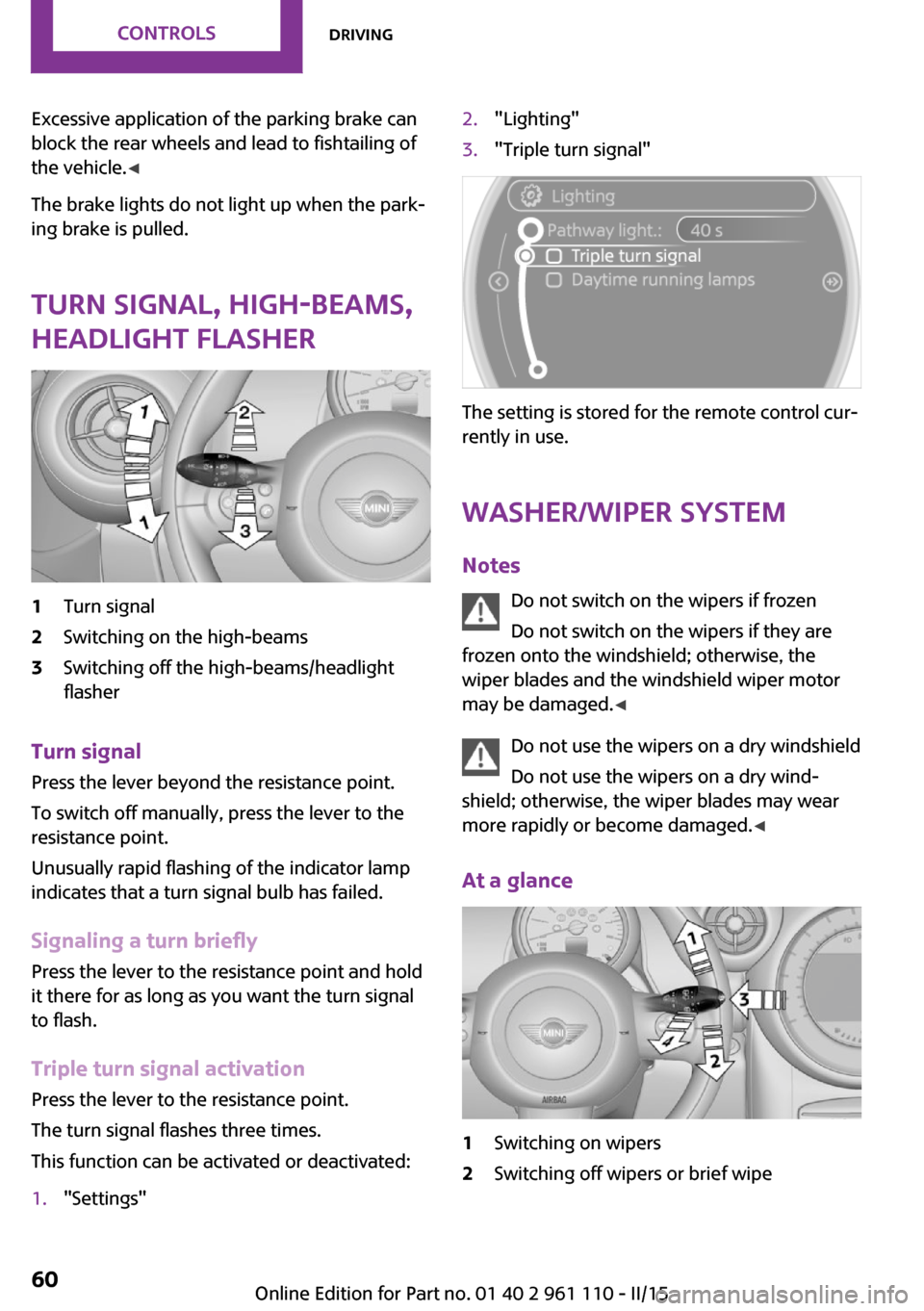
Turn signal, high-beams,
headlight flasher1Turn signal2Switching on the high-beams3Switching off the high-beams/headlight
flasher
Turn signal
Press the lever beyond the resistance point.
To switch off manually, press the lever to the
resistance point.
Unusually rapid flashing of the indicator lamp
indicates that a turn signal bulb has failed.
Signaling a turn briefly Press the lever to the resistance point and hold
it there for as long as you want the turn signal
to flash.
Triple turn signal activation Press the lever to the resistance point.
The turn signal flashes three times.
This function can be activated or deactivated:
1."Settings"2."Lighting"3."Triple turn signal"
The setting is stored for the remote control cur‐
rently in use.
Washer/wiper system
Notes Do not switch on the wipers if frozen
Do not switch on the wipers if they are
frozen onto the windshield; otherwise, the
wiper blades and the windshield wiper motor
may be damaged. ◀
Do not use the wipers on a dry windshield
Do not use the wipers on a dry wind‐
shield; otherwise, the wiper blades may wear
more rapidly or become damaged. ◀
At a glance
1Switching on wipers2Switching off wipers or brief wipeSeite 60CONTROLSDriving60
Online Edition for Part no. 01 40 2 961 110 - II/15
Page 69 of 283

DisplaysVehicle equipment
This chapter describes all series equipment as
well as country-specific and special equipment
offered for this model series. Therefore, it also
describes equipment that may not be found in
your vehicle, for instance due to the selected
special equipment or the country version. This
also applies to safety-related functions and sys‐
tems.
When using the features and systems described
here, adhere to local regulations.
Odometer, external tem‐
perature display, clock
At a glance1Current speed2Odometer, trip odometer, external temper‐
ature, time3Resetting the trip odometer
Press the button on the turn indicator lever to
open information in display area 2.
The following information is displayed consecu‐
tively:
▷Trip odometer▷Time▷External temperatureTrip odometer
Displaying the trip odometer Press button 3 briefly.
Resetting the trip odometer1.Press button 3 briefly.
The trip odometer is displayed.2.Press button 3 again.
The trip odometer is reset.
Time
Set the time, refer to page 71.
External temperature, external
temperature warning
If the display drops to +37 ℉/+3 ℃, a signal
sounds and a warning light lights up. There is
the increased danger of ice.
Ice on roads
Even at temperatures above
+37 ℉/+3 ℃, there can be a risk of ice on
roads.
Therefore, drive carefully on bridges and shady
roads, for example, to avoid the increased dan‐
ger of an accident. ◀
Units of measure To set the respective units of measure, miles or
km for the odometer and ℃ or ℉ for the exter‐
nal temperature, refer to page 71.
Seite 67DisplaysCONTROLS67
Online Edition for Part no. 01 40 2 961 110 - II/15
Page 76 of 283
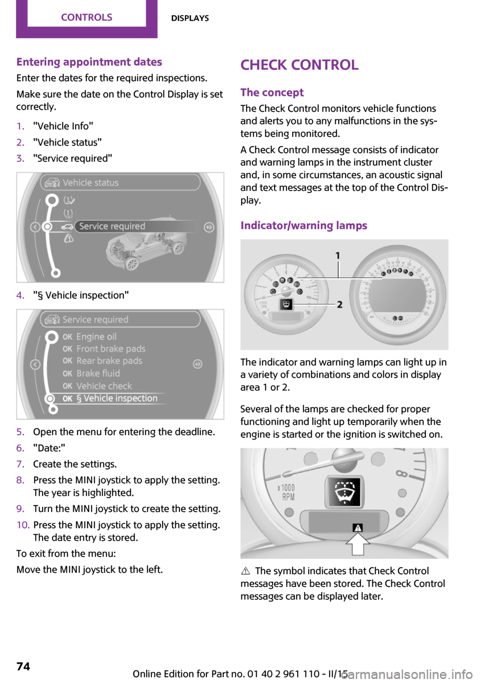
Entering appointment dates
Enter the dates for the required inspections.
Make sure the date on the Control Display is set
correctly.1."Vehicle Info"2."Vehicle status"3."Service required"4."§ Vehicle inspection"5.Open the menu for entering the deadline.6."Date:"7.Create the settings.8.Press the MINI joystick to apply the setting.
The year is highlighted.9.Turn the MINI joystick to create the setting.10.Press the MINI joystick to apply the setting.
The date entry is stored.
To exit from the menu:
Move the MINI joystick to the left.
Check Control
The concept
The Check Control monitors vehicle functions
and alerts you to any malfunctions in the sys‐
tems being monitored.
A Check Control message consists of indicator
and warning lamps in the instrument cluster
and, in some circumstances, an acoustic signal
and text messages at the top of the Control Dis‐
play.
Indicator/warning lamps
The indicator and warning lamps can light up in
a variety of combinations and colors in display
area 1 or 2.
Several of the lamps are checked for proper
functioning and light up temporarily when the
engine is started or the ignition is switched on.
The symbol indicates that Check Control
messages have been stored. The Check Control
messages can be displayed later.
Seite 74CONTROLSDisplays74
Online Edition for Part no. 01 40 2 961 110 - II/15
Page 80 of 283
For example, the sensors are unable to detect
fog or hazy weather. To avoid safety risks, you
should always switch on the lamps manually
under these conditions. ◀
The exterior lighting goes out automatically af‐
ter the vehicle is switched off.
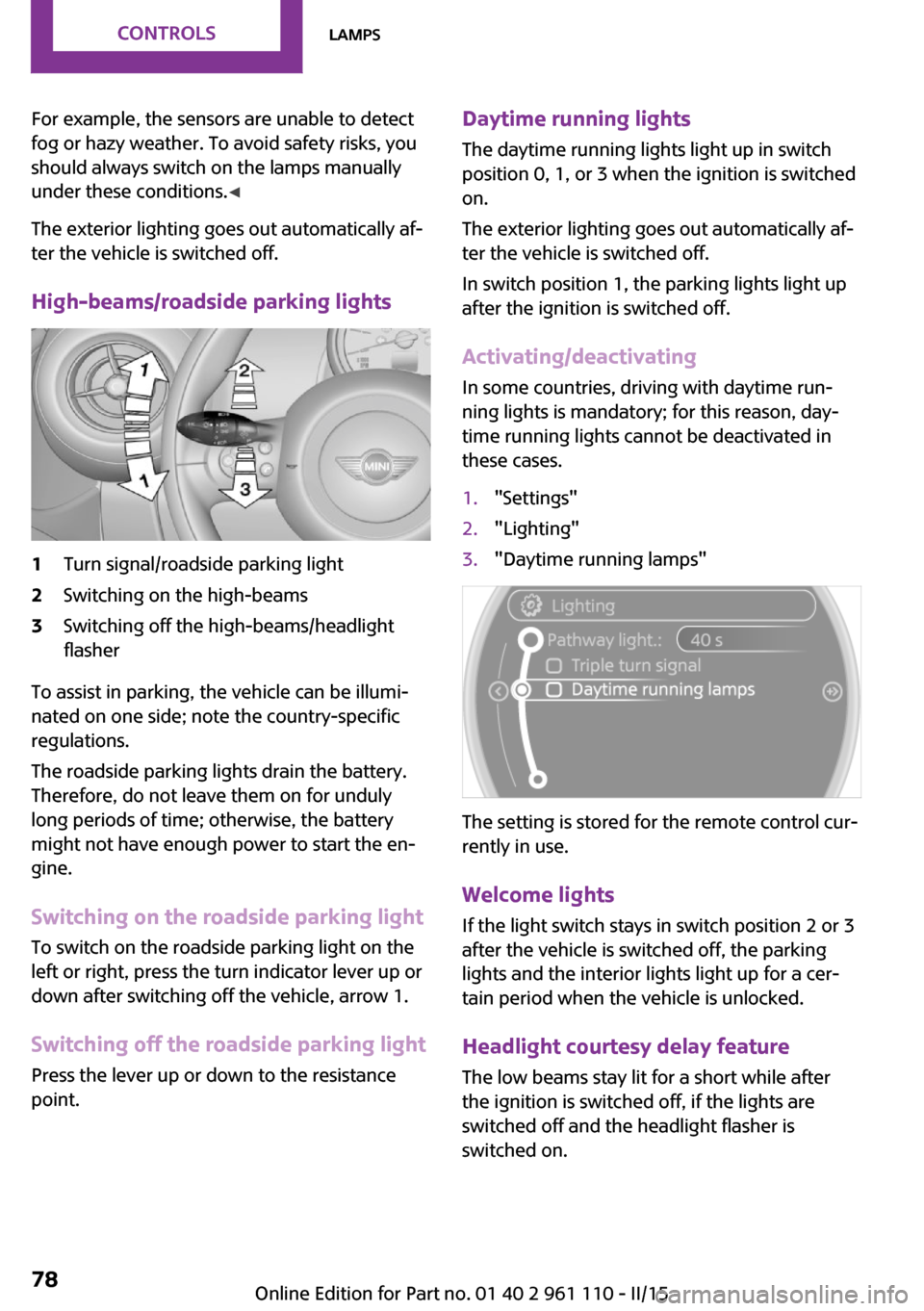
High-beams/roadside parking lights1Turn signal/roadside parking light2Switching on the high-beams3Switching off the high-beams/headlight
flasher
To assist in parking, the vehicle can be illumi‐
nated on one side; note the country-specific
regulations.
The roadside parking lights drain the battery.
Therefore, do not leave them on for unduly
long periods of time; otherwise, the battery
might not have enough power to start the en‐
gine.
Switching on the roadside parking light
To switch on the roadside parking light on the
left or right, press the turn indicator lever up or
down after switching off the vehicle, arrow 1.
Switching off the roadside parking light
Press the lever up or down to the resistance
point.
Daytime running lights
The daytime running lights light up in switch
position 0, 1, or 3 when the ignition is switched
on.
The exterior lighting goes out automatically af‐
ter the vehicle is switched off.
In switch position 1, the parking lights light up
after the ignition is switched off.
Activating/deactivating
In some countries, driving with daytime run‐
ning lights is mandatory; for this reason, day‐
time running lights cannot be deactivated in
these cases.1."Settings"2."Lighting"3."Daytime running lamps"
The setting is stored for the remote control cur‐
rently in use.
Welcome lights If the light switch stays in switch position 2 or 3
after the vehicle is switched off, the parking
lights and the interior lights light up for a cer‐
tain period when the vehicle is unlocked.
Headlight courtesy delay feature The low beams stay lit for a short while after
the ignition is switched off, if the lights are
switched off and the headlight flasher is
switched on.
Seite 78CONTROLSLamps78
Online Edition for Part no. 01 40 2 961 110 - II/15
Page 92 of 283
Declaration according to NHTSA/FMVSS
138 Tire Pressure Monitoring Systems
Each tire, including the spare (if provided)
should be checked monthly when cold and in‐
flated to the inflation pressure recommended
by the vehicle manufacturer on the vehicle
placard or tire inflation pressure label (If your
vehicle has tires of a different size than the size indicated on the vehicle placard or tire inflation
pressure label, you should determine the
proper tire inflation pressure for those tires.).
As an added safety feature, your vehicle has
been equipped with a tire pressure monitoring
system (TPMS) that illuminates a low tire pres‐
sure telltale when one or more of your tires is
significantly under-inflated. Accordingly, when
the low tire pressure telltale illuminates, you
should stop and check your tires as soon as
possible, and inflate them to the proper pres‐
sure. Driving on a significantly under-inflated
tire causes the tire to overheat and can lead to
tire failure. Under-inflation also reduces fuel ef‐
ficiency and tire tread life, and may affect the
vehicle's handling and stopping ability.
Please note that the TPMS is not a substitute for proper tire maintenance, and it is the driver's
responsibility to maintain correct tire pressure,
even if under-inflation has not reached the
level to trigger illumination of the TPMS low tire
pressure telltale.
Your vehicle has also been equipped with a
TPMS malfunction indicator to indicate when
the system is not operating properly. The TPMS
malfunction indicator is combined with the low
tire pressure telltale. When the system detects
a malfunction, the telltale will flash for approxi‐
mately one minute and then remain continu‐
ously illuminated. This sequence will continue
upon subsequent vehicle startups as long as
the malfunction exists. When the malfunction
indicator is illuminated, the system may not be
able to detect or signal low tire pressure as in‐
tended. TPMS malfunctions may occur for a va‐
riety of reasons, including the installation of re‐
placement or alternate tires or wheels on thevehicle that prevent the TPMS from functioning
properly. Always check the TPMS malfunction
telltale after replacing one or more tires or
wheels on your vehicle to ensure that the re‐
placement or alternate tires and wheels allow
the TPMS to continue to function properly.
Speed limit The concept
Enter a speed for which a Check Control mes‐
sage will be displayed when the speed is
reached. This enables you to receive warnings if
you exceed a speed limit in an urban area, for
example.
You are only warned of reaching this speed a
second time if your vehicle speed falls below it
again by at least 3 mph/5 km/h.
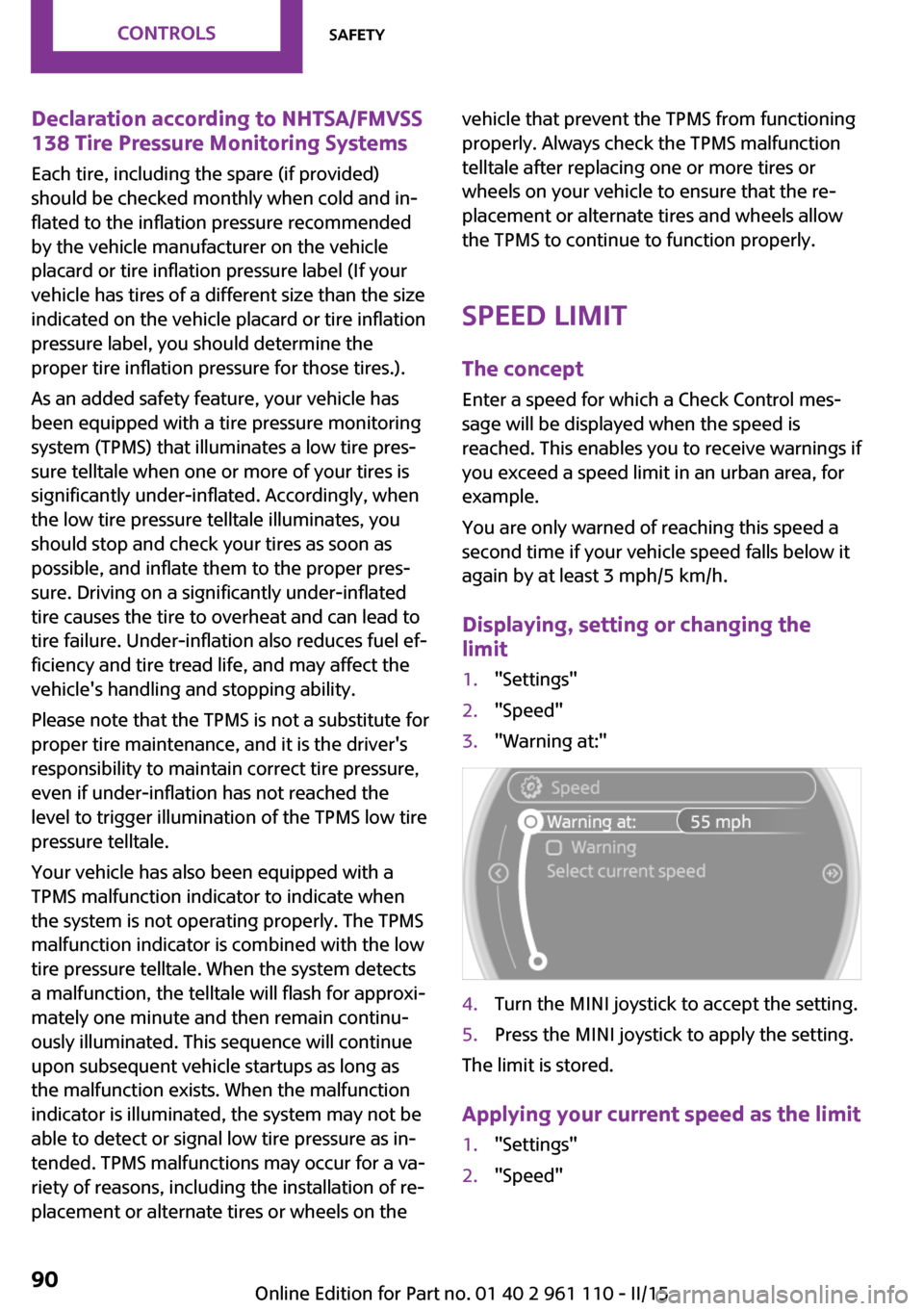
Displaying, setting or changing the
limit1."Settings"2."Speed"3."Warning at:"4.Turn the MINI joystick to accept the setting.5.Press the MINI joystick to apply the setting.
The limit is stored.
Applying your current speed as the limit
1."Settings"2."Speed"Seite 90CONTROLSSafety90
Online Edition for Part no. 01 40 2 961 110 - II/15
Page 156 of 283
ToneVehicle equipmentThis chapter describes all series equipment as
well as country-specific and special equipment
offered for this model series. Therefore, it also
describes equipment that may not be found in
your vehicle, for instance due to the selected
special equipment or the country version. This
also applies to safety-related functions and sys‐
tems.
When using the features and systems described
here, adhere to local regulations.
General information
The sound settings are stored for the remote
control currently in use.
Treble, bass, balance,
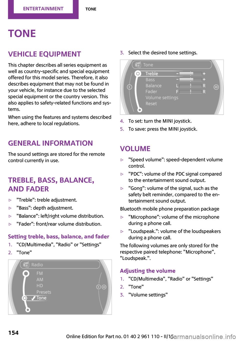
and fader▷"Treble": treble adjustment.▷"Bass": depth adjustment.▷"Balance": left/right volume distribution.▷"Fader": front/rear volume distribution.
Setting treble, bass, balance, and fader
1."CD/Multimedia", "Radio" or "Settings"2."Tone"3.Select the desired tone settings.4.To set: turn the MINI joystick.5.To save: press the MINI joystick.
Volume
▷"Speed volume": speed-dependent volume
control.▷"PDC": volume of the PDC signal compared
to the entertainment sound output.▷"Gong": volume of the signal, such as the
safety belt reminder, compared to the en‐
tertainment sound output.
Bluetooth mobile phone preparation package
▷"Microphone": volume of the microphone
during a phone call.▷"Loudspeak.": volume of the loudspeakers
during a phone call.
The following volumes are only stored for the
respective paired telephone: "Microphone",
"Loudspeak.".
Adjusting the volume
1."CD/Multimedia", "Radio" or "Settings"2."Tone"3."Volume settings"Seite 154ENTERTAINMENTTone154
Online Edition for Part no. 01 40 2 961 110 - II/15