tailgate MINI Countryman 2015 User Guide
[x] Cancel search | Manufacturer: MINI, Model Year: 2015, Model line: Countryman, Model: MINI Countryman 2015Pages: 223, PDF Size: 5.46 MB
Page 102 of 223

MINI Paceman
Take out the cover.
Cargo area Cargo cover Do not place objects on the covers
Do not place objects on the cover; if you
do so, they may pose a danger to vehicle occu‐
pants during braking or evasive maneuvers or
damage the cover. ◀
Move the cover into position
When closing, ensure that the cargo cover
is resting on the rubber buffers of the securing
straps; otherwise, damage may occur when
closing the tailgate. ◀
When the tailgate is opened, the cargo cover is
raised.
To load bulky luggage, the cover can be re‐
moved.
1.Detach the securing straps from the tail‐
gate.2.Lift the cover slightly, arrow 1, and pull it
back and out of the bracket, arrow 2.
MINI Countryman:
MINI Paceman:
MINI Countryman: rear seat backrests
Danger of pinching
Before folding down the rear seat back‐
rests, ensure that path of movement of the
backrests is clear. Especially when the middle
section is folded down, ensure that no one is
located in or reaches into the path of move‐ ment of the rear seat backrests. Otherwise, in‐
juries or damage may result. ◀
Observe the instructions concerning the
safety belt
Observe the instructions concerning the safety
belt, refer to page 37. Otherwise, personal pro‐
tection may be compromised. ◀
The rear seat backrest is divided at a ratio of 40-20-40.
When the outer rear seat backrests are folded down, it is not permissible for a person to travel
on the center seat.
Remove the third head restraint, refer to
page 40, if necessary.
Seite 100CONTROLSInterior equipment100
Online Edition for Part no. 01 40 2 961 084 - II/15
Page 104 of 223
partment during braking maneuvers and
swerving, endangering the occupants. ◀
Flat loading floor Maximum load
Do not exceed the maximum load of
330 lbs, 150 kg, on the loading floor; otherwise,
damage may result. ◀
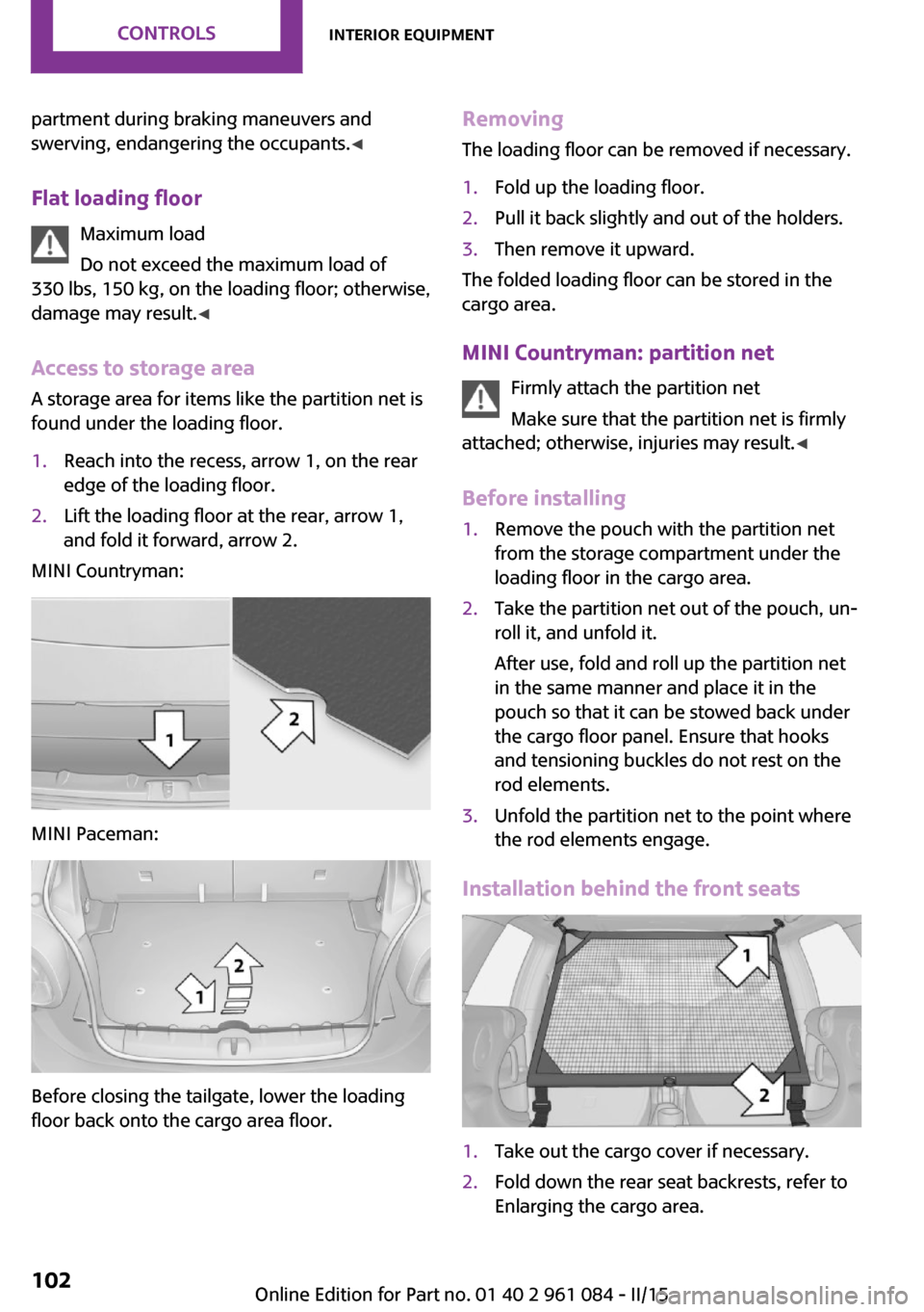
Access to storage area
A storage area for items like the partition net is
found under the loading floor.1.Reach into the recess, arrow 1, on the rear
edge of the loading floor.2.Lift the loading floor at the rear, arrow 1,
and fold it forward, arrow 2.
MINI Countryman:
MINI Paceman:
Before closing the tailgate, lower the loading
floor back onto the cargo area floor.
Removing
The loading floor can be removed if necessary.1.Fold up the loading floor.2.Pull it back slightly and out of the holders.3.Then remove it upward.
The folded loading floor can be stored in the
cargo area.
MINI Countryman: partition net Firmly attach the partition net
Make sure that the partition net is firmly
attached; otherwise, injuries may result. ◀
Before installing
1.Remove the pouch with the partition net
from the storage compartment under the
loading floor in the cargo area.2.Take the partition net out of the pouch, un‐
roll it, and unfold it.
After use, fold and roll up the partition net
in the same manner and place it in the
pouch so that it can be stowed back under
the cargo floor panel. Ensure that hooks
and tensioning buckles do not rest on the
rod elements.3.Unfold the partition net to the point where
the rod elements engage.
Installation behind the front seats
1.Take out the cargo cover if necessary.2.Fold down the rear seat backrests, refer to
Enlarging the cargo area.Seite 102CONTROLSInterior equipment102
Online Edition for Part no. 01 40 2 961 084 - II/15
Page 113 of 223

Closing the tailgateDrive with the tailgate closed
Only drive with the tailgate closed; other‐
wise, passengers and other road users may be
endangered or the vehicle may be damaged if
an accident occurs or during braking or swerv‐
ing. In addition, exhaust fumes may enter the
passenger compartment. ◀
If, despite this, the vehicle must be driven with
the tailgate open:▷Drive moderately.▷Close all windows and the glass sunroof.▷Switch off recirculated air mode and greatly
increase the blower speed.
Hot exhaust system
Hot exhaust system
High temperatures are generated in the
exhaust system.
Do not remove the heat shields installed and
never apply undercoating to them. Make sure
that flammable materials, e. g. hay, leaves,
grass, etc. do not come in contact with the hot
exhaust system during driving, while in idle po‐
sition mode, or when parked. Such contact
could lead to a fire, and with it the risk of seri‐
ous personal injury as well as property damage.
Do not touch hot exhaust pipes; otherwise,
there is the danger of getting burned. ◀
Mobile communication devices in the
vehicle
Mobile communication devices in the ve‐
hicle
It is not recommended to use mobile phones,
such as mobile phones without a direct con‐
nection to an external aerial in the vehicle's
passenger compartment. Otherwise, the vehi‐
cle electronics and mobile communication de‐
vices can interfere with each other. In addition,
there is no assurance that the radiation gener‐
ated during transmission will be discharged
from the vehicle interior. ◀
Hydroplaning On wet or slushy roads, a wedge of water can
form between the tires and road surface.
This phenomenon is referred to as hydroplan‐
ing. It is characterized by a partial or complete
loss of contact between the tires and the road
surface, ultimately undermining your ability to
steer and brake the vehicle.
Hydroplaning
When driving on wet or slushy roads, re‐
duce your speed to prevent hydroplaning. ◀
The risk of hydroplaning increases as the tire
tread depth decreases. Minimum tread depth,
refer to page 158.
Driving through water Drive though calm water only if it is not deeper
than 12 inches/30 cm and at this height, no
faster than walking speed, up to
6 mph/10 km/h.
Using the parking brake on inclines Using the parking brake
On inclines, do not hold the vehicle sta‐
tionary with a slipping clutch for extended pe‐
riod; use the parking brake instead. Otherwise, the clutch will be subject to increased wear. ◀
Support from the hill drive-off assistant, refer to
page 83.
Braking safely The vehicle is equipped with ABS as a standard
feature.
Applying the brakes fully is the most effective
way of braking in situations when this is neces‐
sary.
The vehicle maintains steering responsiveness.
You can still avoid any obstacles with a mini‐
mum of steering effort.Seite 111Things to remember when drivingDRIVING TIPS111
Online Edition for Part no. 01 40 2 961 084 - II/15
Page 119 of 223

▷Distribute the roof load uniformly.▷The roof load should not be too large in
area.▷Always load the heaviest pieces on the bot‐
tom.▷Fasten the roof-mounted luggage securely,
for instance using lashing straps.▷Do not let objects project into the opening
path of the tailgate.▷Drive smoothly. Avoid sudden acceleration
and braking maneuvers. Take corners gen‐
tly.
Rear luggage rack
Notes A special rear rack is available as an optional
accessory. It does not require a trailer hitch.
Follow the installation instructions for the rear
rack.
Anchorage points
MINI Countryman:
MINI Paceman:
The anchorage points are under the covers in
the bumper.
Push out the covers on the corresponding cut‐
outs.
Loading
When loading the vehicle, ensure that the ap‐
proved gross vehicle weight and the axle loads
are not exceeded. Adhere to the weight specifi‐
cations in the technical data.
Seite 117LoadingDRIVING TIPS117
Online Edition for Part no. 01 40 2 961 084 - II/15
Page 178 of 223
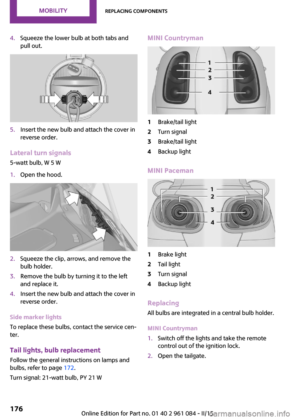
4.Squeeze the lower bulb at both tabs and
pull out.5.Insert the new bulb and attach the cover in
reverse order.
Lateral turn signals
5-watt bulb, W 5 W
1.Open the hood.2.Squeeze the clip, arrows, and remove the
bulb holder.3.Remove the bulb by turning it to the left
and replace it.4.Insert the new bulb and attach the cover in
reverse order.
Side marker lights
To replace these bulbs, contact the service cen‐
ter.
Tail lights, bulb replacement
Follow the general instructions on lamps and
bulbs, refer to page 172.
Turn signal: 21-watt bulb, PY 21 W
MINI Countryman1Brake/tail light2Turn signal3Brake/tail light4Backup light
MINI Paceman
1Brake light2Tail light3Turn signal4Backup light
Replacing
All bulbs are integrated in a central bulb holder.
MINI Countryman
1.Switch off the lights and take the remote
control out of the ignition lock.2.Open the tailgate.Seite 176MOBILITYReplacing components176
Online Edition for Part no. 01 40 2 961 084 - II/15
Page 179 of 223
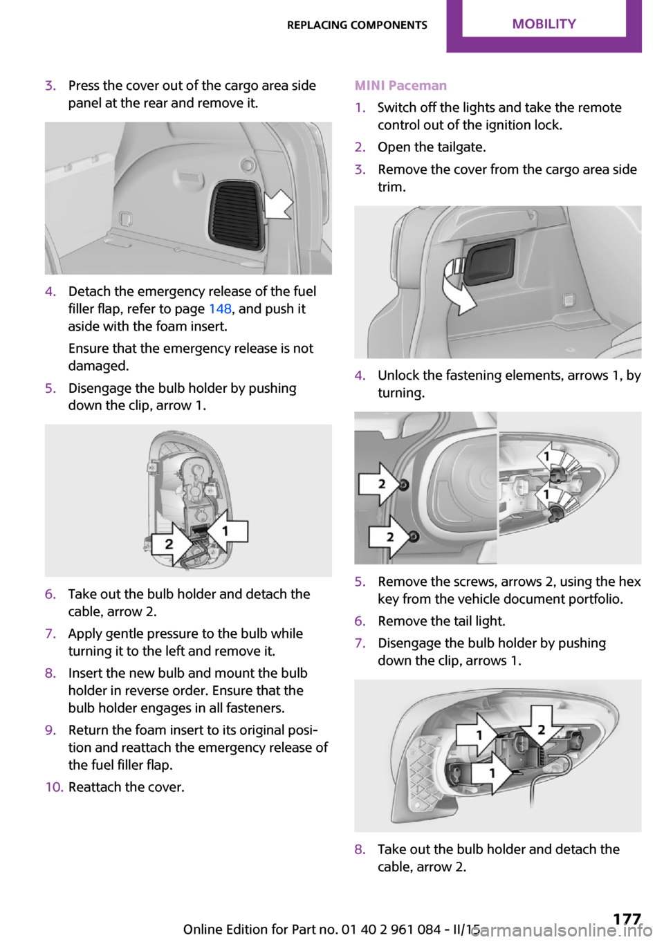
3.Press the cover out of the cargo area side
panel at the rear and remove it.4.Detach the emergency release of the fuel
filler flap, refer to page 148, and push it
aside with the foam insert.
Ensure that the emergency release is not
damaged.5.Disengage the bulb holder by pushing
down the clip, arrow 1.6.Take out the bulb holder and detach the
cable, arrow 2.7.Apply gentle pressure to the bulb while
turning it to the left and remove it.8.Insert the new bulb and mount the bulb
holder in reverse order. Ensure that the
bulb holder engages in all fasteners.9.Return the foam insert to its original posi‐
tion and reattach the emergency release of
the fuel filler flap.10.Reattach the cover.MINI Paceman1.Switch off the lights and take the remote
control out of the ignition lock.2.Open the tailgate.3.Remove the cover from the cargo area side
trim.4.Unlock the fastening elements, arrows 1, by
turning.5.Remove the screws, arrows 2, using the hex
key from the vehicle document portfolio.6.Remove the tail light.7.Disengage the bulb holder by pushing
down the clip, arrows 1.8.Take out the bulb holder and detach the
cable, arrow 2.Seite 177Replacing componentsMOBILITY177
Online Edition for Part no. 01 40 2 961 084 - II/15
Page 194 of 223
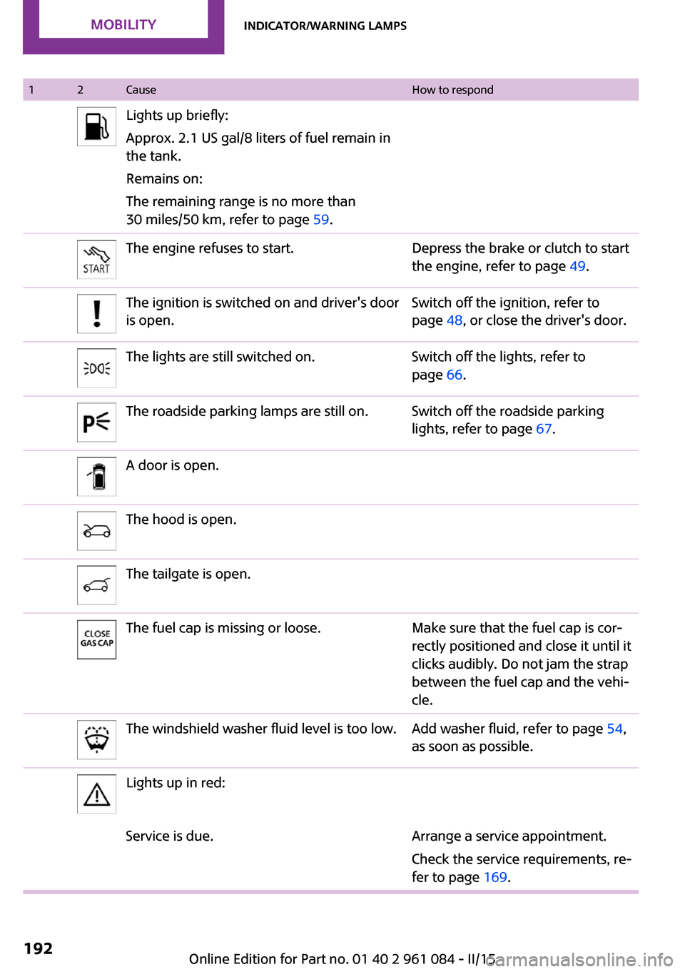
12CauseHow to respondLights up briefly:
Approx. 2.1 US gal/8 liters of fuel remain in
the tank.
Remains on:
The remaining range is no more than
30 miles/50 km, refer to page 59.The engine refuses to start.Depress the brake or clutch to start
the engine, refer to page 49.The ignition is switched on and driver's door
is open.Switch off the ignition, refer to
page 48, or close the driver's door.The lights are still switched on.Switch off the lights, refer to
page 66.The roadside parking lamps are still on.Switch off the roadside parking
lights, refer to page 67.A door is open.The hood is open.The tailgate is open.The fuel cap is missing or loose.Make sure that the fuel cap is cor‐
rectly positioned and close it until it
clicks audibly. Do not jam the strap
between the fuel cap and the vehi‐
cle.The windshield washer fluid level is too low.Add washer fluid, refer to page 54,
as soon as possible.Lights up in red:Service is due.Arrange a service appointment.
Check the service requirements, re‐
fer to page 169.Seite 192MOBILITYIndicator/warning lamps192
Online Edition for Part no. 01 40 2 961 084 - II/15
Page 219 of 223
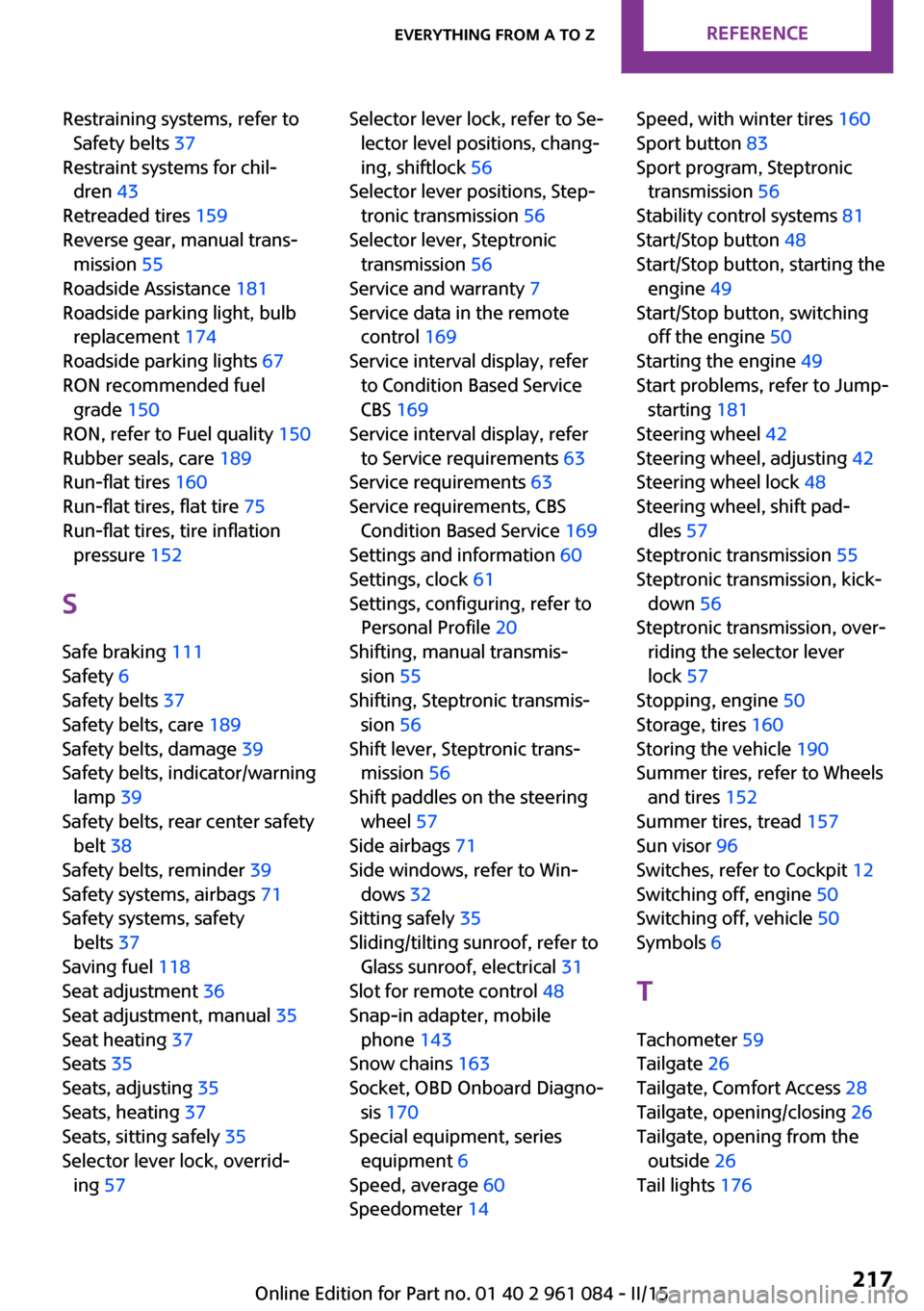
Restraining systems, refer toSafety belts 37
Restraint systems for chil‐ dren 43
Retreaded tires 159
Reverse gear, manual trans‐ mission 55
Roadside Assistance 181
Roadside parking light, bulb replacement 174
Roadside parking lights 67
RON recommended fuel grade 150
RON, refer to Fuel quality 150
Rubber seals, care 189
Run-flat tires 160
Run-flat tires, flat tire 75
Run-flat tires, tire inflation pressure 152
S
Safe braking 111
Safety 6
Safety belts 37
Safety belts, care 189
Safety belts, damage 39
Safety belts, indicator/warning lamp 39
Safety belts, rear center safety belt 38
Safety belts, reminder 39
Safety systems, airbags 71
Safety systems, safety belts 37
Saving fuel 118
Seat adjustment 36
Seat adjustment, manual 35
Seat heating 37
Seats 35
Seats, adjusting 35
Seats, heating 37
Seats, sitting safely 35
Selector lever lock, overrid‐ ing 57 Selector lever lock, refer to Se‐
lector level positions, chang‐
ing, shiftlock 56
Selector lever positions, Step‐ tronic transmission 56
Selector lever, Steptronic transmission 56
Service and warranty 7
Service data in the remote control 169
Service interval display, refer to Condition Based Service
CBS 169
Service interval display, refer to Service requirements 63
Service requirements 63
Service requirements, CBS Condition Based Service 169
Settings and information 60
Settings, clock 61
Settings, configuring, refer to Personal Profile 20
Shifting, manual transmis‐ sion 55
Shifting, Steptronic transmis‐ sion 56
Shift lever, Steptronic trans‐ mission 56
Shift paddles on the steering wheel 57
Side airbags 71
Side windows, refer to Win‐ dows 32
Sitting safely 35
Sliding/tilting sunroof, refer to Glass sunroof, electrical 31
Slot for remote control 48
Snap-in adapter, mobile phone 143
Snow chains 163
Socket, OBD Onboard Diagno‐ sis 170
Special equipment, series equipment 6
Speed, average 60
Speedometer 14 Speed, with winter tires 160
Sport button 83
Sport program, Steptronic transmission 56
Stability control systems 81
Start/Stop button 48
Start/Stop button, starting the engine 49
Start/Stop button, switching off the engine 50
Starting the engine 49
Start problems, refer to Jump- starting 181
Steering wheel 42
Steering wheel, adjusting 42
Steering wheel lock 48
Steering wheel, shift pad‐ dles 57
Steptronic transmission 55
Steptronic transmission, kick‐ down 56
Steptronic transmission, over‐ riding the selector lever
lock 57
Stopping, engine 50
Storage, tires 160
Storing the vehicle 190
Summer tires, refer to Wheels and tires 152
Summer tires, tread 157
Sun visor 96
Switches, refer to Cockpit 12
Switching off, engine 50
Switching off, vehicle 50
Symbols 6
T Tachometer 59
Tailgate 26
Tailgate, Comfort Access 28
Tailgate, opening/closing 26
Tailgate, opening from the outside 26
Tail lights 176 Seite 217Everything from A to ZREFERENCE217
Online Edition for Part no. 01 40 2 961 084 - II/15
Page 220 of 223
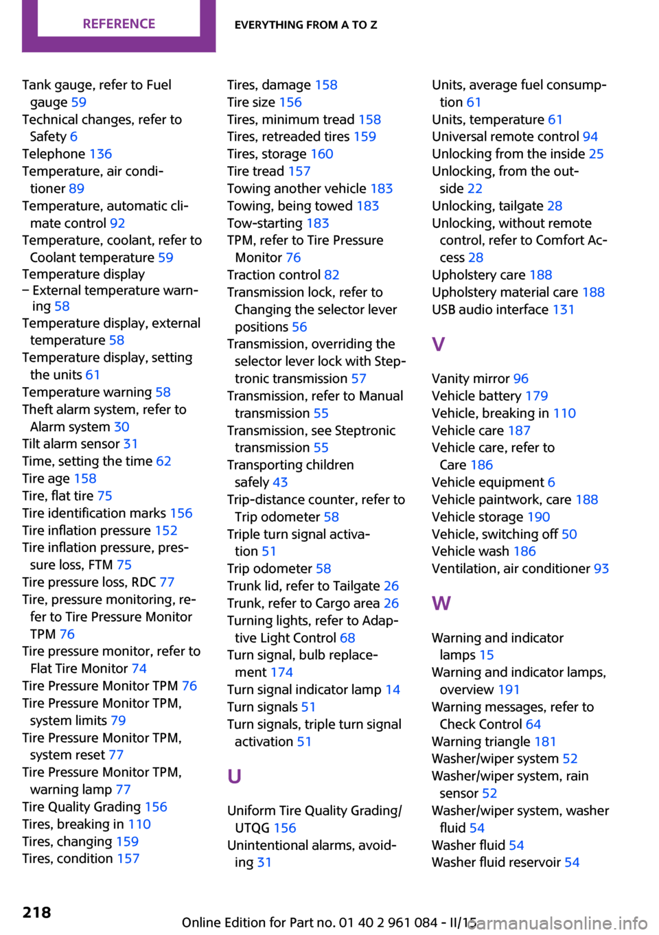
Tank gauge, refer to Fuelgauge 59
Technical changes, refer to Safety 6
Telephone 136
Temperature, air condi‐ tioner 89
Temperature, automatic cli‐ mate control 92
Temperature, coolant, refer to Coolant temperature 59
Temperature display– External temperature warn‐
ing 58
Temperature display, external
temperature 58
Temperature display, setting the units 61
Temperature warning 58
Theft alarm system, refer to Alarm system 30
Tilt alarm sensor 31
Time, setting the time 62
Tire age 158
Tire, flat tire 75
Tire identification marks 156
Tire inflation pressure 152
Tire inflation pressure, pres‐ sure loss, FTM 75
Tire pressure loss, RDC 77
Tire, pressure monitoring, re‐ fer to Tire Pressure Monitor
TPM 76
Tire pressure monitor, refer to Flat Tire Monitor 74
Tire Pressure Monitor TPM 76
Tire Pressure Monitor TPM, system limits 79
Tire Pressure Monitor TPM, system reset 77
Tire Pressure Monitor TPM, warning lamp 77
Tire Quality Grading 156
Tires, breaking in 110
Tires, changing 159
Tires, condition 157
Tires, damage 158
Tire size 156
Tires, minimum tread 158
Tires, retreaded tires 159
Tires, storage 160
Tire tread 157
Towing another vehicle 183
Towing, being towed 183
Tow-starting 183
TPM, refer to Tire Pressure Monitor 76
Traction control 82
Transmission lock, refer to Changing the selector lever
positions 56
Transmission, overriding the selector lever lock with Step‐
tronic transmission 57
Transmission, refer to Manual transmission 55
Transmission, see Steptronic transmission 55
Transporting children safely 43
Trip-distance counter, refer to Trip odometer 58
Triple turn signal activa‐ tion 51
Trip odometer 58
Trunk lid, refer to Tailgate 26
Trunk, refer to Cargo area 26
Turning lights, refer to Adap‐ tive Light Control 68
Turn signal, bulb replace‐ ment 174
Turn signal indicator lamp 14
Turn signals 51
Turn signals, triple turn signal activation 51
U
Uniform Tire Quality Grading/ UTQG 156
Unintentional alarms, avoid‐ ing 31 Units, average fuel consump‐
tion 61
Units, temperature 61
Universal remote control 94
Unlocking from the inside 25
Unlocking, from the out‐ side 22
Unlocking, tailgate 28
Unlocking, without remote control, refer to Comfort Ac‐
cess 28
Upholstery care 188
Upholstery material care 188
USB audio interface 131
V Vanity mirror 96
Vehicle battery 179
Vehicle, breaking in 110
Vehicle care 187
Vehicle care, refer to Care 186
Vehicle equipment 6
Vehicle paintwork, care 188
Vehicle storage 190
Vehicle, switching off 50
Vehicle wash 186
Ventilation, air conditioner 93
W
Warning and indicator lamps 15
Warning and indicator lamps, overview 191
Warning messages, refer to Check Control 64
Warning triangle 181
Washer/wiper system 52
Washer/wiper system, rain sensor 52
Washer/wiper system, washer fluid 54
Washer fluid 54
Washer fluid reservoir 54 Seite 218REFERENCEEverything from A to Z218
Online Edition for Part no. 01 40 2 961 084 - II/15