ESP MINI Countryman 2016 (Mini Connected) User Guide
[x] Cancel search | Manufacturer: MINI, Model Year: 2016, Model line: Countryman, Model: MINI Countryman 2016Pages: 282, PDF Size: 6.79 MB
Page 54 of 282

securely against the backrest. If possible, adjust
the backrest tilt for all affected backrests and
correctly adjust the seats. Make sure that seats
and backrests are securely engaged. If possible,
adjust the height of the head restraints or re‐
move them. ◀
Installing child re‐ straint fixing systems
Before mounting MINI Countryman: before mounting a child re‐
straint fixing system on the rear seats, move
the seats into the rearmost positions.
Adjust the inclination of the center backrest to
that of the respective outer backrest.
After mounting the child restraint fixing system
on the respective outer rear seat, adjust the
backrest forward, if necessary, to ensure that
the backrest is in contact with the child re‐
straint fixing system. Rear seat backrests, refer
to page 111.
Information Pay attention to the specifications of the child
restraint system manufacturer when selecting,
installing, and using child restraint systems.
WARNING
The stability of the child restraint system
is limited or compromised with incorrect seat
adjustment or improper installation of the child seat. There is risk of injuries or danger to life.
Make sure that the child restraint system fits
securely against the backrest. If possible, adjust
the backrest tilt for all affected backrests and
correctly adjust the seats. Make sure that seats
and backrests are securely engaged. If possible,
adjust the height of the head restraints or re‐
move them. ◀On the front passenger seat
Deactivating the airbags After installing a child restraint fixing system on
the front passenger seat, ensure that the front,
side, and knee airbags on the front passenger
side are deactivated.
Seat position and height Before installing a child restraint fixing system,move the front passenger seat as far back aspossible and adjust its height to the highest po‐
sition to obtain the best possible position for
the belt and to offer optimal protection in the
event of an accident.
Do not change this seat position once it has
been set.
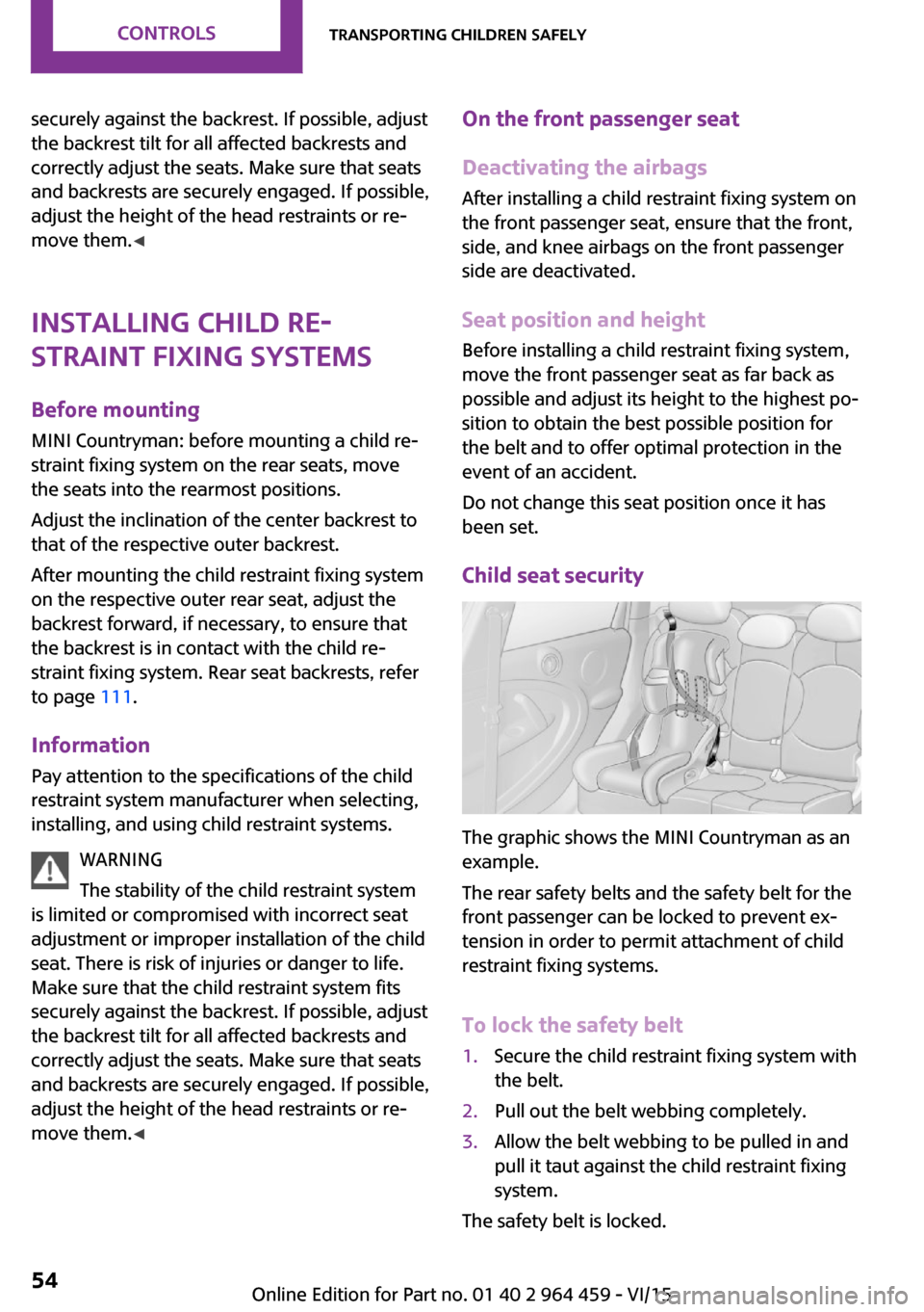
Child seat security
The graphic shows the MINI Countryman as an
example.
The rear safety belts and the safety belt for the
front passenger can be locked to prevent ex‐
tension in order to permit attachment of child
restraint fixing systems.
To lock the safety belt
1.Secure the child restraint fixing system with
the belt.2.Pull out the belt webbing completely.3.Allow the belt webbing to be pulled in and
pull it taut against the child restraint fixing
system.
The safety belt is locked.
Seite 54CONTROLSTransporting children safely54
Online Edition for Part no. 01 40 2 964 459 - VI/15
Page 55 of 282

To unlock the safety belt1.Open the belt buckle.2.Remove the child restraint fixing system.3.Allow the belt webbing to be pulled in com‐
pletely.
Center safety belt: unlock belt buckle 3 in
addition, refer to page 48.
Guide the safety belt to the holder on the
headliner.
LATCH child restraint fix‐
ing system
LATCH: Lower Anchors and Tethers for Children.
Information
Pay attention to the operating and safety infor‐
mation of the child restraint system manufac‐
turer when installing and using LATCH child re‐
straint fixing system.
Mounts for the lower LATCH anchors
The lower anchors may be used to attach the
CRS to the vehicle seat up to a combined child
and CRS weight of 65 lb/30 kg when the child is
restrained by the internal harnesses.
WARNING
If the LATCH child restraint fixing systems
are not correctly engaged, the protective effect
of the LATCH child restraint fixing system can
be limited. There is risk of injuries or danger to
life. Make sure that the lower anchors are se‐
curely engaged and that the LATCH child re‐
straint fixing system fits securely against the
backrest. ◀
Before installing the child seat, pull the belt out
of the area for the child restraint fixing system.
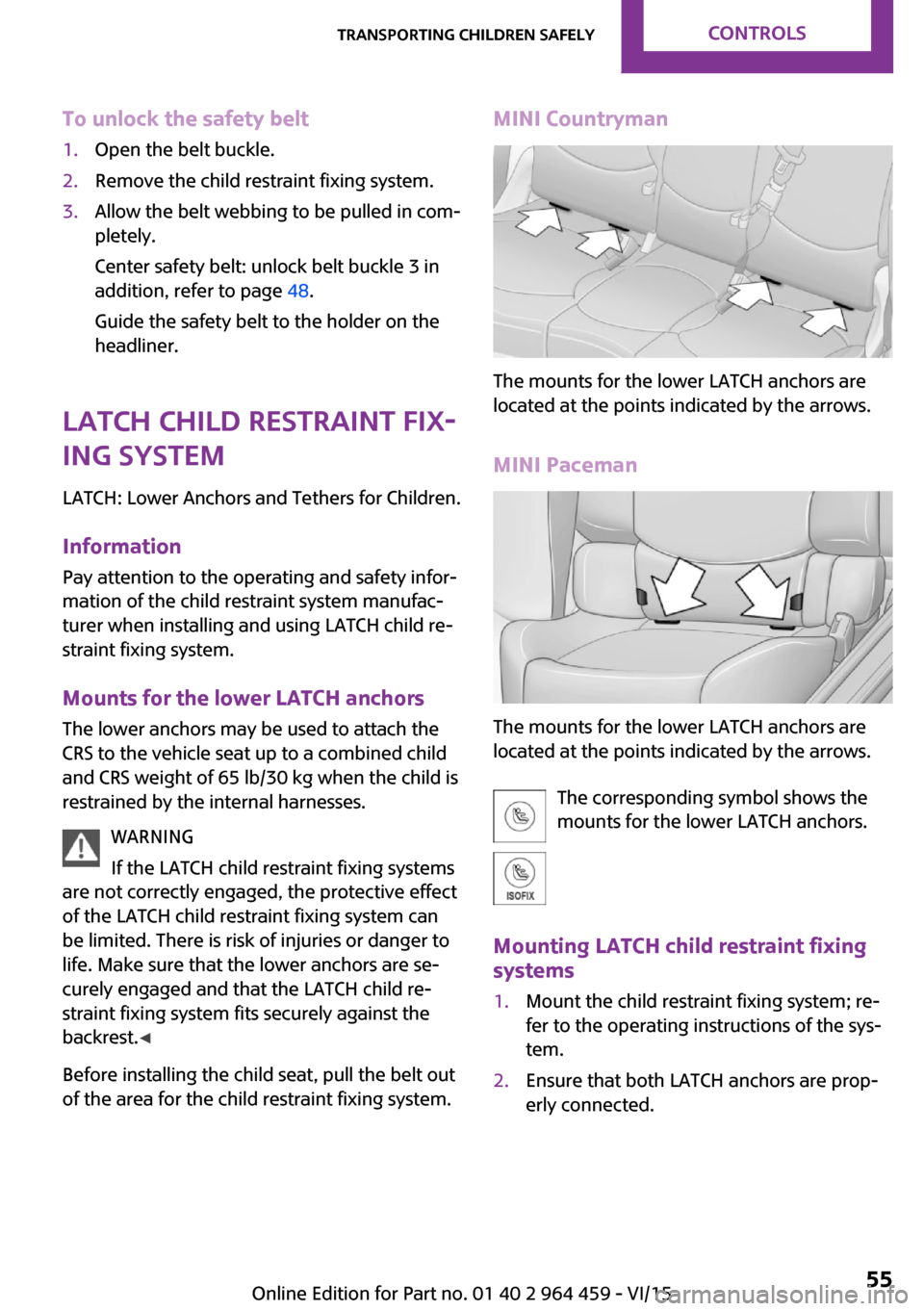
MINI Countryman
The mounts for the lower LATCH anchors are
located at the points indicated by the arrows.
MINI Paceman
The mounts for the lower LATCH anchors are
located at the points indicated by the arrows.
The corresponding symbol shows the
mounts for the lower LATCH anchors.
Mounting LATCH child restraint fixing systems
1.Mount the child restraint fixing system; re‐
fer to the operating instructions of the sys‐
tem.2.Ensure that both LATCH anchors are prop‐
erly connected.Seite 55Transporting children safelyCONTROLS55
Online Edition for Part no. 01 40 2 964 459 - VI/15
Page 68 of 282

DisplaysVehicle features and op‐tions
This chapter describes all standard, country-
specific and optional features offered with the
series. It also describes features that are not
necessarily available in your car, e. g., due to
the selected options or country versions. This
also applies to safety-related functions and sys‐
tems.
When using the features and systems described
here, adhere to local regulations.
Odometer, external tem‐
perature display, clock
Overview1Current speed2Odometer, trip odometer, external temper‐
ature, time3Resetting the trip odometer
Press the button on the turn indicator lever to
open information in display area 2.
The following information is displayed consecu‐
tively:
▷Trip odometer▷Time▷External temperatureTrip odometer
Displaying the trip odometer Press button 3 briefly.
Resetting the trip odometer1.Press button 3 briefly.
The trip odometer is displayed.2.Press button 3 again.
The trip odometer is reset.
Time
Set the time, refer to page 72.
External temperature, external
temperature warning
If the display drops to +37 ℉/+3 ℃, a signal
sounds and a warning light lights up. There is
the increased danger of ice.
WARNING
Even at temperatures above +37 ℉/+3 ℃
there can be a danger of icy roads, e.g. on
bridges or shady sections of road. There is risk
of an accident. Adjust your driving style to the
weather conditions at low temperatures ◀
Units of measure
To set the respective units of measure, miles or
km for the odometer and ℃ or ℉ for the exter‐
nal temperature, refer to page 72.
Seite 68CONTROLSDisplays68
Online Edition for Part no. 01 40 2 964 459 - VI/15
Page 70 of 282

▷Current fuel consumption.▷Average speed.
To set the corresponding units of measure, re‐
fer to page 72.
Information in detail
Range
Displays the estimated cruising range available
with the remaining fuel.
It is calculated based on your driving style over
the last 18 miles/30 km.
Average fuel consumption
This is calculated for the period during which
the engine is running.
With the trip computer, refer to page 70, the
average consumption can be displayed for an
additional distance.
To reset the average consumption: press the
button on the turn indicator lever for ap‐
prox. 2 seconds.
Current fuel consumption Displays the current fuel consumption. You can
check whether you are currently driving in an
efficient and environmentally-friendly manner.
Average speed Periods in which the vehicle was parked and
the engine was switched off manually are not
included in the average speed calculations.
With the trip computer, refer to page 70, the
average speed can be displayed for an addi‐
tional distance.
To reset the average speed: press the button
on the turn indicator lever for approx. 2 sec‐
onds.
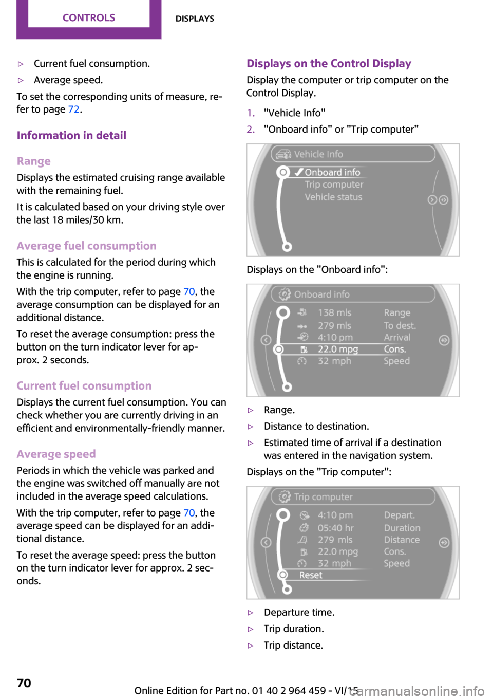
Displays on the Control Display
Display the computer or trip computer on the
Control Display.1."Vehicle Info"2."Onboard info" or "Trip computer"
Displays on the "Onboard info":
▷Range.▷Distance to destination.▷Estimated time of arrival if a destination
was entered in the navigation system.
Displays on the "Trip computer":
▷Departure time.▷Trip duration.▷Trip distance.Seite 70CONTROLSDisplays70
Online Edition for Part no. 01 40 2 964 459 - VI/15
Page 71 of 282

Both displays show:▷Average fuel consumption.▷Average speed.
Resetting the fuel consumption and
speed
Resetting the values for average speed and
average fuel consumption:
1.Select the respective menu item and press
the MINI joystick.2.Press the MINI joystick again to confirm
your selection.
Resetting the trip computer
Resetting all values:
1."Vehicle Info"2."Trip computer"3."Reset"
Settings and information
Operating concept
Some settings and information can only be cre‐
ated or opened while the ignition is switched
on, the vehicle is standing, and the doors are
closed.
1Button for:▷Selecting the display.▷Setting values.▷Confirming the selected display or set
values.▷Calling up computer information 69.SymbolFunctionSet the rain sensor, refer to
page 62.Open Check-Control, refer to
page 75.Exit the menu.
Exiting displays
1.Press the button on the turn indicator lever
repeatedly until "HOME" is displayed.2.Hold the button down.
The current speed is displayed again.
Displays are also exited if no entries are made
within approx. 8 seconds.
Seite 71DisplaysCONTROLS71
Online Edition for Part no. 01 40 2 964 459 - VI/15
Page 76 of 282

Text messages
Text messages at the upper edge of the Control
Display in combination with a symbol in the in‐
strument cluster explain a Check Control mes‐
sage and the meaning of the indicator and warning lights.
Supplementary text messages
Additional information, such as on the cause of a fault or the required action, can be called up
via Check Control.
In urgent cases, this information will be shown
as soon as the corresponding light comes on.
Hiding Check Control messages
Press the button on the turn indicator lever.
Some Check Control messages are displayed
continuously and are not cleared until the mal‐
function is eliminated. If several malfunctions
occur at once, the messages are displayed con‐
secutively.
They are marked with the symbol
shown here.
Other Check Control messages are hidden au‐
tomatically after approx. 20 seconds. However,
they are stored and can be displayed again
later.
They are marked with the symbol
shown here.
Viewing stored Check Control messages The stored Check Control messages can only be
displayed while the driver's door is closed.1.Press the button on the turn indicator lever
repeatedly until "SET/INFO" is displayed.2.Press and hold the button until the display
changes.3.Press the button repeatedly until the corre‐
sponding symbol and "CHECK INFO" ap‐
pear on the display.4.Press and hold the button.
If there is no Check Control message, this is
indicated by "CHECK OK".
If a Check Control message has been
stored, the corresponding message is dis‐
played.Seite 76CONTROLSDisplays76
Online Edition for Part no. 01 40 2 964 459 - VI/15
Page 80 of 282

Setting the duration1."Settings"2."Lighting"3."Pathway light.: s"4.Set the duration.
Settings are stored for the remote control cur‐
rently in use.
Adaptive Light Control
The concept
Adaptive Light Control is a variable headlight
control system that enables dynamic illumina‐
tion of the road surface.
Depending on the steering angle and other pa‐
rameters, the light from the headlight follows
the course of the road.
Activating
With the ignition switch on, turn the light switch
to position 3, refer to page 78.
To avoid blinding oncoming traffic, the Adap‐
tive Light Control does not swivel to the driver's
side when the vehicle is at a standstill.
When driving in reverse, Adaptive Light Control
is not active.
Malfunction The warning light lights up. A message
appears on the Control Display. Adap‐
tive Light Control is malfunctioning or
has failed. Have the system checked as soon as
possible.
Fog lights Overview
To switch on the front fog lights: press the
switch.
To switch off, press the respective switch up‐
ward or downward again.
Fog lights The parking lights or low beams must be
switched on. The green indicator lamp lights up
when the front fog lights are switched on.
Depending on the vehicle equipment, the front
fog lights are switched off when the headlight
flasher or the high-beams are activated.
If the automatic headlight control is activated,
refer to page 78, the low beams are switched
on automatically when the front fog lights are
switched on.
Instrument lighting The parking lights or low beams must be
switched on to adjust the brightness. The
brightness is increased to a certain limit and is then reduced again.
Seite 80CONTROLSLamps80
Online Edition for Part no. 01 40 2 964 459 - VI/15
Page 82 of 282

SafetyVehicle features and op‐
tions
This chapter describes all standard, country-
specific and optional features offered with the
series. It also describes features that are not
necessarily available in your car, e. g., due to
the selected options or country versions. This
also applies to safety-related functions and sys‐
tems.When using the features and systems described
here, adhere to local regulations.
Airbags
The graphic shows the MINI Paceman as an ex‐ ample.1Front airbags2Knee airbag3Side airbag4Head airbagsFront airbags
Front airbags help protect the driver and front
passenger by responding to frontal impacts in
which safety belts alone cannot provide ade‐
quate restraint.Side airbags
In a lateral impact, the side airbag supports the
side of the body in the chest and lap area.
Head airbags
In a lateral impact, the head airbag supports
the head.Seite 82CONTROLSSafety82
Online Edition for Part no. 01 40 2 964 459 - VI/15
Page 84 of 282

WARNING
The ensure the front-seat passenger air‐
bag function, it must be detected, whether a
person occupies the front passenger seat. The
entire seat cushion area must be used for this
purpose. There is risk of injuries or danger to
life. Make sure that the front passenger keeps
his or her feet in the floor area. ◀
Malfunction of the automatic
deactivation system
When transporting older children and adults,
the front passenger airbags may be deactivated
in certain sitting positions. In this case, the indi‐
cator lamp for the front passenger airbags
lights up.
In this case, change the sitting position so that
the front passenger airbags are activated and
the indicator lamp goes out.
If it is not possible to activate the airbags, have
the person sit in the rear.
To make sure that occupation of the seat cush‐
ion can be detected correctly:▷Do not attach covers, cushions, ball mats or
other items to the front passenger seat un‐
less they are specifically determined to be
safe for use on the front passenger seat.▷Do not place electronic devices on the pas‐
senger seat if a child restraint fixing system
is mounted on the seat.▷Do not place objects under the seat that
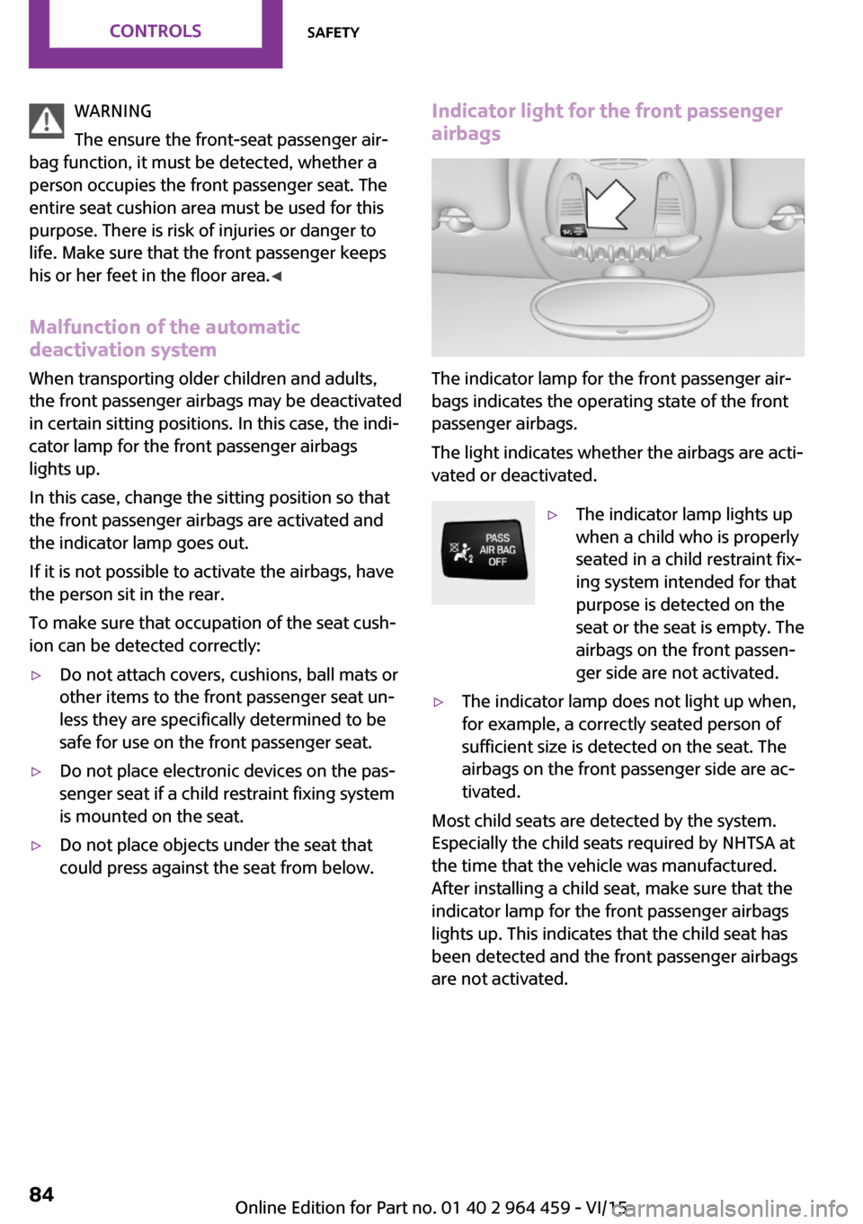
could press against the seat from below.Indicator light for the front passenger airbags
The indicator lamp for the front passenger air‐
bags indicates the operating state of the front
passenger airbags.
The light indicates whether the airbags are acti‐
vated or deactivated.
▷The indicator lamp lights up
when a child who is properly
seated in a child restraint fix‐
ing system intended for that
purpose is detected on the
seat or the seat is empty. The
airbags on the front passen‐
ger side are not activated.▷The indicator lamp does not light up when,
for example, a correctly seated person of
sufficient size is detected on the seat. The
airbags on the front passenger side are ac‐
tivated.
Most child seats are detected by the system.
Especially the child seats required by NHTSA at
the time that the vehicle was manufactured.
After installing a child seat, make sure that the
indicator lamp for the front passenger airbags
lights up. This indicates that the child seat has
been detected and the front passenger airbags
are not activated.
Seite 84CONTROLSSafety84
Online Edition for Part no. 01 40 2 964 459 - VI/15
Page 85 of 282

Operational readiness of airbag system
Information WARNING
Individual components can be hot after
triggering of the airbag system. There is risk of
injuries. Do not touch individual components. ◀
WARNING
Improperly executed work can lead to
failure, malfunction or unintentional triggering of the airbag system. In the case of a malfunc‐
tion, the airbag system could not trigger as in‐ tended in the event of an accident despite re‐
spective accident severity. There is risk of
injuries or danger to life. Have the airbag sys‐
tem checked, repaired, dismantled and scrap‐
ped by a dealer’s service center or another
qualified service center or repair shop. ◀
Correct function
In the radio ready state and beyond, re‐
fer to page 58, the warning light lights
up briefly to indicate that the entire air‐
bag system and the belt tensioners are opera‐
tional.
Airbag system malfunction
▷Warning light does not light up in the radio
ready state.▷Warning light remains permanently on.
The airbag restraint system and belt tensioner
are not working. Have the vehicle checked im‐
mediately by a dealer’s service center or an‐
other qualified service center or repair shop.
FTM Flat Tire Monitor
The concept
The system does not measure the actual infla‐
tion pressure in the tires.
The system detects a pressure loss in a tire by
comparing the rotational speeds of the individ‐
ual wheels while moving.
In the event of a pressure loss, the diameter
and therefore the rotational speed of the corre‐
sponding wheel change. This is detected and
reported as a flat tire.
Functional requirements
The system must have been initialized when
the tire inflation pressure was correct; other‐ wise, reliable signaling of a flat tire is not en‐
sured.
Initialize the system after each correction of the
tire inflation pressure and after every tire or
wheel change.
System limits
A natural, even pressure loss in all four tires
cannot be detected. Therefore, check the tire
inflation pressure regularly.
Sudden serious tire damage caused by external
influences cannot be indicated in advance.
The system could be delayed or malfunction in
the following situations:▷When the system has not been initialized.▷When driving on a snowy or slippery road
surface.▷Sporty driving style: slip in the drive wheels,
high lateral acceleration.▷When driving with snow chains.Seite 85SafetyCONTROLS85
Online Edition for Part no. 01 40 2 964 459 - VI/15