height adjustment MINI Countryman 2016 Owner's Manual (Mini Connected)
[x] Cancel search | Manufacturer: MINI, Model Year: 2016, Model line: Countryman, Model: MINI Countryman 2016Pages: 282, PDF Size: 6.79 MB
Page 45 of 282
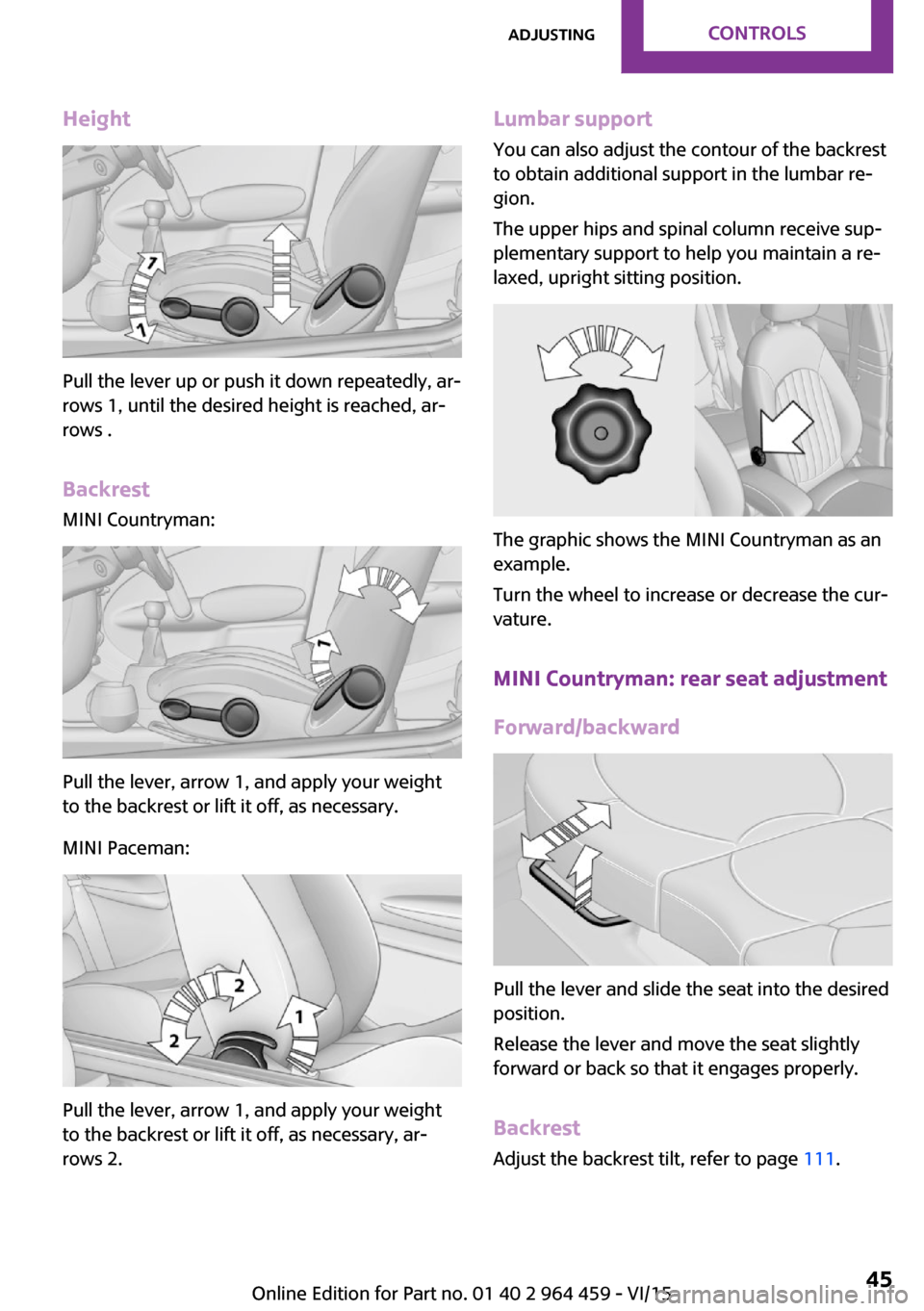
Height
Pull the lever up or push it down repeatedly, ar‐
rows 1, until the desired height is reached, ar‐
rows .
Backrest MINI Countryman:
Pull the lever, arrow 1, and apply your weight
to the backrest or lift it off, as necessary.
MINI Paceman:
Pull the lever, arrow 1, and apply your weight
to the backrest or lift it off, as necessary, ar‐
rows 2.
Lumbar support
You can also adjust the contour of the backrest
to obtain additional support in the lumbar re‐
gion.
The upper hips and spinal column receive sup‐
plementary support to help you maintain a re‐
laxed, upright sitting position.
The graphic shows the MINI Countryman as an
example.
Turn the wheel to increase or decrease the cur‐
vature.
MINI Countryman: rear seat adjustmentForward/backward
Pull the lever and slide the seat into the desired
position.
Release the lever and move the seat slightly
forward or back so that it engages properly.
Backrest Adjust the backrest tilt, refer to page 111.
Seite 45AdjustingCONTROLS45
Online Edition for Part no. 01 40 2 964 459 - VI/15
Page 50 of 282
Height adjustment
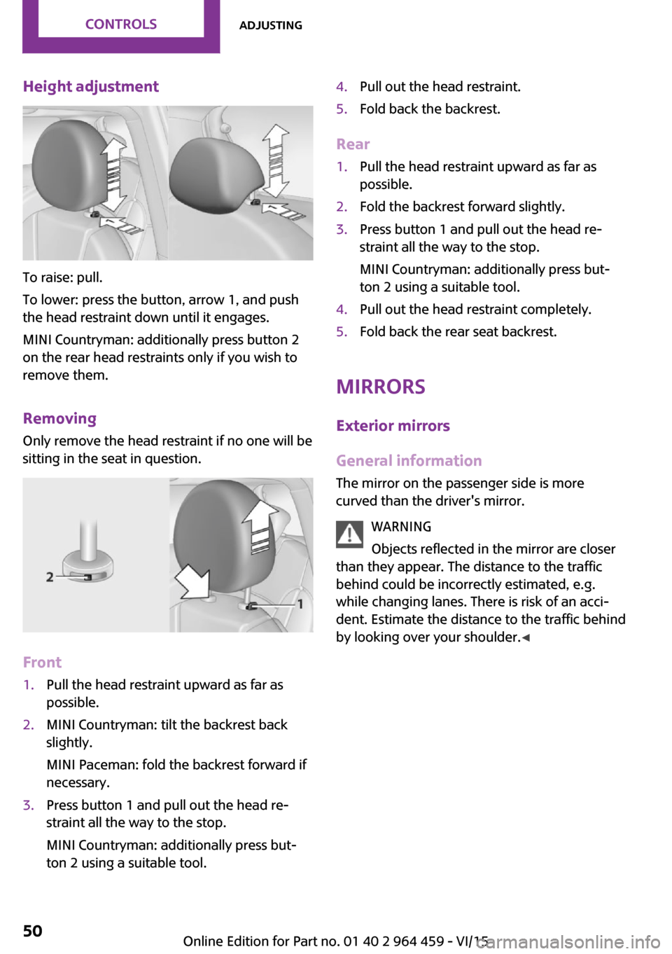
To raise: pull.
To lower: press the button, arrow 1, and push
the head restraint down until it engages.
MINI Countryman: additionally press button 2
on the rear head restraints only if you wish to
remove them.
Removing Only remove the head restraint if no one will be
sitting in the seat in question.
Front
1.Pull the head restraint upward as far as
possible.2.MINI Countryman: tilt the backrest back
slightly.
MINI Paceman: fold the backrest forward if
necessary.3.Press button 1 and pull out the head re‐
straint all the way to the stop.
MINI Countryman: additionally press but‐
ton 2 using a suitable tool.4.Pull out the head restraint.5.Fold back the backrest.
Rear
1.Pull the head restraint upward as far as
possible.2.Fold the backrest forward slightly.3.Press button 1 and pull out the head re‐
straint all the way to the stop.
MINI Countryman: additionally press but‐
ton 2 using a suitable tool.4.Pull out the head restraint completely.5.Fold back the rear seat backrest.
Mirrors
Exterior mirrors
General information
The mirror on the passenger side is more
curved than the driver's mirror.
WARNING
Objects reflected in the mirror are closer
than they appear. The distance to the traffic
behind could be incorrectly estimated, e.g.
while changing lanes. There is risk of an acci‐
dent. Estimate the distance to the traffic behind
by looking over your shoulder. ◀
Seite 50CONTROLSAdjusting50
Online Edition for Part no. 01 40 2 964 459 - VI/15
Page 52 of 282

▷Do not cover the area between the inside
rearview mirror and the windshield.▷Do not apply stickers to the windshield in
front of the mirror.
Steering wheel
Adjusting WARNING
Steering wheel adjustments while driving
can lead to unexpected steering wheel move‐
ments. Vehicle control could be lost. There is
risk of an accident. Adjust the steering wheel
while the vehicle is stationary only. ◀
1.Fold the lever down.2.Move the steering wheel to the preferred
height and angle to suit your seating posi‐
tion.3.Fold the lever back.Seite 52CONTROLSAdjusting52
Online Edition for Part no. 01 40 2 964 459 - VI/15
Page 54 of 282
securely against the backrest. If possible, adjust
the backrest tilt for all affected backrests and
correctly adjust the seats. Make sure that seats
and backrests are securely engaged. If possible,
adjust the height of the head restraints or re‐
move them. ◀
Installing child re‐ straint fixing systems
Before mounting MINI Countryman: before mounting a child re‐
straint fixing system on the rear seats, move
the seats into the rearmost positions.
Adjust the inclination of the center backrest to
that of the respective outer backrest.
After mounting the child restraint fixing system
on the respective outer rear seat, adjust the
backrest forward, if necessary, to ensure that
the backrest is in contact with the child re‐
straint fixing system. Rear seat backrests, refer
to page 111.
Information Pay attention to the specifications of the child
restraint system manufacturer when selecting,
installing, and using child restraint systems.
WARNING
The stability of the child restraint system
is limited or compromised with incorrect seat
adjustment or improper installation of the child seat. There is risk of injuries or danger to life.
Make sure that the child restraint system fits
securely against the backrest. If possible, adjust
the backrest tilt for all affected backrests and
correctly adjust the seats. Make sure that seats
and backrests are securely engaged. If possible,
adjust the height of the head restraints or re‐
move them. ◀On the front passenger seat
Deactivating the airbags After installing a child restraint fixing system on
the front passenger seat, ensure that the front,
side, and knee airbags on the front passenger
side are deactivated.
Seat position and height Before installing a child restraint fixing system,move the front passenger seat as far back aspossible and adjust its height to the highest po‐
sition to obtain the best possible position for
the belt and to offer optimal protection in the
event of an accident.
Do not change this seat position once it has
been set.
Child seat security
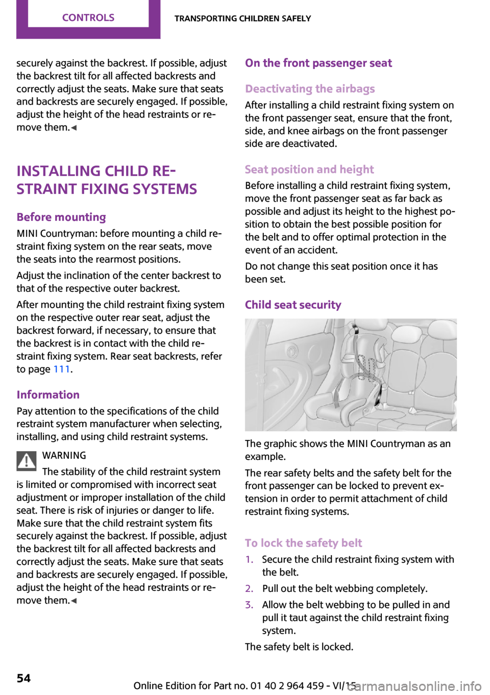
The graphic shows the MINI Countryman as an
example.
The rear safety belts and the safety belt for the
front passenger can be locked to prevent ex‐
tension in order to permit attachment of child
restraint fixing systems.
To lock the safety belt
1.Secure the child restraint fixing system with
the belt.2.Pull out the belt webbing completely.3.Allow the belt webbing to be pulled in and
pull it taut against the child restraint fixing
system.
The safety belt is locked.
Seite 54CONTROLSTransporting children safely54
Online Edition for Part no. 01 40 2 964 459 - VI/15
Page 112 of 282
The backrests can be adjusted to 10 different
positions between the comfort and transport
positions and they can be folded down.
In the comfort position, the backrests are tilted
back to the greatest possible angle and in the
transport position they are nearly vertical.
Before beginning with the mounting of a child
restraint fixing system, note the instructions,
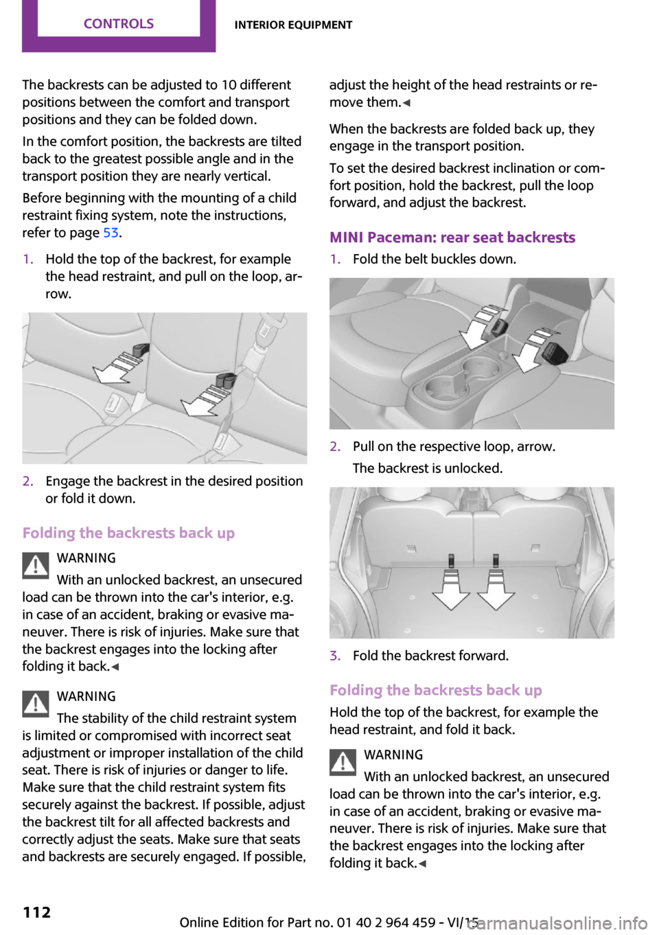
refer to page 53.1.Hold the top of the backrest, for example
the head restraint, and pull on the loop, ar‐
row.2.Engage the backrest in the desired position
or fold it down.
Folding the backrests back up
WARNING
With an unlocked backrest, an unsecured
load can be thrown into the car's interior, e.g.
in case of an accident, braking or evasive ma‐
neuver. There is risk of injuries. Make sure that
the backrest engages into the locking after
folding it back. ◀
WARNING
The stability of the child restraint system
is limited or compromised with incorrect seat
adjustment or improper installation of the child
seat. There is risk of injuries or danger to life.
Make sure that the child restraint system fits
securely against the backrest. If possible, adjust
the backrest tilt for all affected backrests and
correctly adjust the seats. Make sure that seats
and backrests are securely engaged. If possible,
adjust the height of the head restraints or re‐
move them. ◀
When the backrests are folded back up, they
engage in the transport position.
To set the desired backrest inclination or com‐
fort position, hold the backrest, pull the loop
forward, and adjust the backrest.
MINI Paceman: rear seat backrests1.Fold the belt buckles down.2.Pull on the respective loop, arrow.
The backrest is unlocked.3.Fold the backrest forward.
Folding the backrests back up Hold the top of the backrest, for example the
head restraint, and fold it back.
WARNING
With an unlocked backrest, an unsecured
load can be thrown into the car's interior, e.g.
in case of an accident, braking or evasive ma‐
neuver. There is risk of injuries. Make sure that
the backrest engages into the locking after
folding it back. ◀
Seite 112CONTROLSInterior equipment112
Online Edition for Part no. 01 40 2 964 459 - VI/15
Page 274 of 282
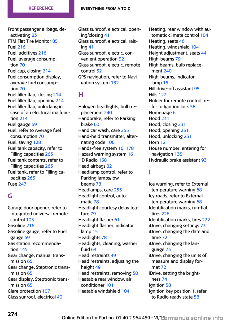
Front passenger airbags, de‐activating 83
FTM Flat Tire Monitor 85
Fuel 216
Fuel, additives 216
Fuel, average consump‐ tion 70
Fuel cap, closing 214
Fuel consumption display, average fuel consump‐
tion 70
Fuel filler flap, closing 214
Fuel filler flap, opening 214
Fuel filler flap, unlocking in case of an electrical malfunc‐
tion 214
Fuel gauge 69
Fuel, refer to Average fuel consumption 70
Fuel, saving 128
Fuel tank capacity, refer to Filling capacities 263
Fuel tank contents, refer to Filling capacities 263
Fuel tank, refer to Filling ca‐ pacities 263
Fuse 247
G Garage door opener, refer to Integrated universal remote
control 105
Gasoline 216
Gasoline gauge, refer to Fuel gauge 69
Gas station recommenda‐ tion 145
Gear change, manual trans‐ mission 65
Gear change, Steptronic trans‐ mission 65
Gear display, Steptronic trans‐ mission 65
Glare protection 107
Glass sunroof, electrical 40 Glass sunroof, electrical, open‐
ing/closing 41
Glass sunroof, electrical, rais‐ ing 41
Glass sunroof, electric, con‐ venient operation 32
Glass sunroof, electric, remote control 32
GPS navigation, refer to Navi‐ gation system 132
H Halogen headlights, bulb re‐ placement 240
Handbrake, refer to Parking brake 60
Hand car wash, care 255
Hand-held transmitter, alter‐ nating code 106
Hands-free system 16, 178
Hazard warning system 16
HD Radio 158
Head airbags 82
Headlamp control, refer to Parking lamps/low
beams 78
Headlamps, care 255
Headlight control, auto‐ matic 78
Headlight courtesy delay fea‐ ture 79
Headlight flasher 61
Headlight flasher, indicator lamp 15
Headlights 78
Headlights, cleaning, washer fluid 64
Head restraints 49
Head restraints, adjusting the height 49
Head restraints, removing 50
Heatable rear window, air conditioner 101
Heatable windshield 104 Heating, rear window with au‐
tomatic climate control 104
Heating, seats 46
Heating, windshield 104
Height adjustment, seats 44
High-beams 79
High beams, bulb replace‐ ment 240
High-beams, indicator lamp 15
Hill drive-off assistant 95
Hills 122
Holder for remote control, re‐ fer to Ignition lock 58
Homepage 6
Hood 231
Hood, closing 231
Hood, opening 231
Hood, unlocking 231
Horn 12
House number, entering for navigation 135
Hydraulic brake assistant 93
I Ice warning, refer to External temperature warning 68
Icy roads, refer to External temperature warning 68
Identification marks, run-flat tires 226
Identification marks, tires 222
iDrive, changing settings 73
iDrive, changing the date and time 72
iDrive, changing the lan‐ guage 73
iDrive, changing the units of measure and display for‐
mat 72
iDrive, setting the bright‐ ness 74
Ignition 58
Ignition key position 1, refer to Radio ready state 58 Seite 274REFERENCEEverything from A to Z274
Online Edition for Part no. 01 40 2 964 459 - VI/15