Start MINI Countryman 2016 Owner's Guide
[x] Cancel search | Manufacturer: MINI, Model Year: 2016, Model line: Countryman, Model: MINI Countryman 2016Pages: 223, PDF Size: 5.52 MB
Page 80 of 223
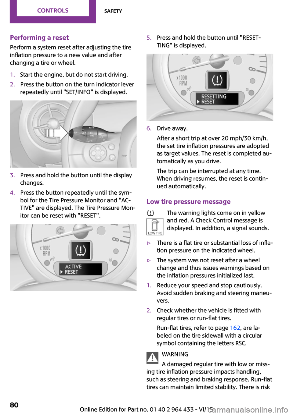
Performing a reset
Perform a system reset after adjusting the tire
inflation pressure to a new value and after
changing a tire or wheel.1.Start the engine, but do not start driving.2.Press the button on the turn indicator lever
repeatedly until "SET/INFO" is displayed.3.Press and hold the button until the display
changes.4.Press the button repeatedly until the sym‐
bol for the Tire Pressure Monitor and "AC‐
TIVE" are displayed. The Tire Pressure Mon‐
itor can be reset with "RESET".5.Press and hold the button until "RESET‐
TING" is displayed.6.Drive away.
After a short trip at over 20 mph/30 km/h,
the set tire inflation pressures are adopted
as target values. The reset is completed au‐
tomatically as you drive.
The trip can be interrupted at any time.
When driving resumes, the reset is contin‐
ued automatically.
Low tire pressure message
The warning lights come on in yellow
and red. A Check Control message is
displayed. In addition, a signal sounds.
▷There is a flat tire or substantial loss of infla‐
tion pressure on the indicated wheel.▷The system was not reset after a wheel
change and thus issues warnings based on
the inflation pressures initialized last.1.Reduce your speed and stop cautiously.
Avoid sudden braking and steering maneu‐
vers.2.Check whether the vehicle is fitted with
regular tires or run-flat tires.
Run-flat tires, refer to page 162, are la‐
beled on the tire sidewall with a circular
symbol containing the letters RSC.
WARNING
A damaged regular tire with low or miss‐
ing tire inflation pressure impacts handling,
such as steering and braking response. Run-flat
tires can maintain limited stability. There is risk
Seite 80CONTROLSSafety80
Online Edition for Part no. 01 40 2 964 433 - VI/15
Page 83 of 223
As an added safety feature, your vehicle has
been equipped with a tire pressure monitoring
system (TPMS) that illuminates a low tire pres‐
sure telltale when one or more of your tires is
significantly under-inflated. Accordingly, when
the low tire pressure telltale illuminates, you
should stop and check your tires as soon as
possible, and inflate them to the proper pres‐
sure. Driving on a significantly under-inflated
tire causes the tire to overheat and can lead to
tire failure. Under-inflation also reduces fuel ef‐
ficiency and tire tread life, and may affect the
vehicle's handling and stopping ability.
Please note that the TPMS is not a substitute for
proper tire maintenance, and it is the driver's
responsibility to maintain correct tire pressure,
even if under-inflation has not reached the
level to trigger illumination of the TPMS low tire
pressure telltale.
Your vehicle has also been equipped with a
TPMS malfunction indicator to indicate when
the system is not operating properly. The TPMS
malfunction indicator is combined with the low
tire pressure telltale. When the system detects
a malfunction, the telltale will flash for approxi‐
mately one minute and then remain continu‐
ously illuminated. This sequence will continue
upon subsequent vehicle startups as long as
the malfunction exists. When the malfunction
indicator is illuminated, the system may not be
able to detect or signal low tire pressure as in‐
tended. TPMS malfunctions may occur for a va‐
riety of reasons, including the installation of re‐
placement or alternate tires or wheels on the
vehicle that prevent the TPMS from functioning
properly. Always check the TPMS malfunction
telltale after replacing one or more tires or
wheels on your vehicle to ensure that the re‐
placement or alternate tires and wheels allow
the TPMS to continue to function properly.Seite 83SafetyCONTROLS83
Online Edition for Part no. 01 40 2 964 433 - VI/15
Page 84 of 223

Driving stability control systemsVehicle features and op‐
tions
This chapter describes all standard, country-
specific and optional features offered with the
series. It also describes features that are not
necessarily available in your car, e. g., due to
the selected options or country versions. This
also applies to safety-related functions and sys‐
tems.
When using the features and systems described
here, adhere to local regulations.
Antilock Brake System
ABS
ABS prevents locking of the wheels during braking.
Steerability is maintained even during full brak‐ ing. This increases active driving safety.
ABS is operational every time you start the en‐
gine.
Electronic brake-force distribution EBVThe system controls the brake pressure in the
rear wheels to ensure stable braking behavior.
CBC Cornering Brake Control When braking in curves or during a lane
change, driving stability and steering response
are improved further.
Brake assistant
When the brakes are applied rapidly, this sys‐
tem automatically produces the maximum
braking force boost. In this way, the system
helps keep the braking distance as short aspossible. This system utilizes all of the benefits
provided by ABS.
Do not reduce the pressure on the brake pedal
for the duration of full braking.
Dynamic Stability Con‐
trol DSC
The concept
DSC prevents traction loss in the driving wheels
when driving away and accelerating.
DSC also recognizes unstable vehicle condi‐
tions, such as fishtailing or nose-diving. Subject
to physical limits, DSC helps to keep the vehicle
on a steady course by reducing engine speed
and by applying brakes to the individual
wheels.
Adapt your driving style to the situation, for an
appropriate driving style is always the responsi‐
bility of the driver.
DSC is operational every time you start the en‐
gine.
WARNING
When driving with roof load, e.g. with
roof-mounted luggage rack, driving safety may
not be ensured in driving-critical situations due
to the elevated center of gravity. There is risk of
accidents or risk of property damage. Do not
deactivate Dynamic Stability Control DSC when
driving with roof load. ◀Seite 84CONTROLSDriving stability control systems84
Online Edition for Part no. 01 40 2 964 433 - VI/15
Page 85 of 223
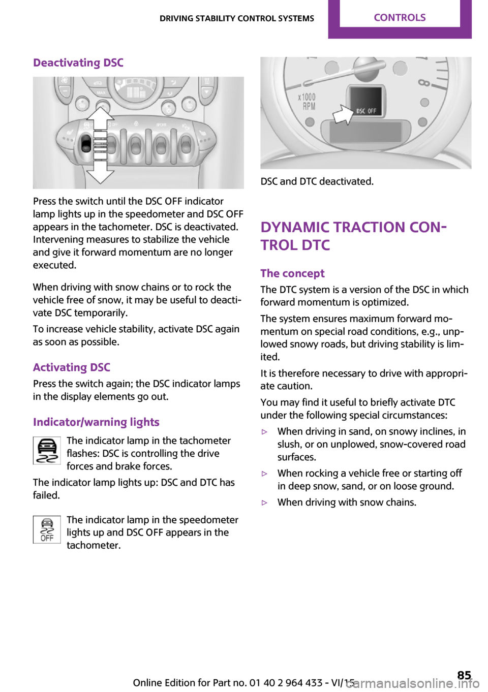
Deactivating DSC
Press the switch until the DSC OFF indicator
lamp lights up in the speedometer and DSC OFF
appears in the tachometer. DSC is deactivated.
Intervening measures to stabilize the vehicle
and give it forward momentum are no longer
executed.
When driving with snow chains or to rock the
vehicle free of snow, it may be useful to deacti‐
vate DSC temporarily.
To increase vehicle stability, activate DSC again
as soon as possible.
Activating DSC
Press the switch again; the DSC indicator lamps
in the display elements go out.
Indicator/warning lights The indicator lamp in the tachometer
flashes: DSC is controlling the drive
forces and brake forces.
The indicator lamp lights up: DSC and DTC has
failed.
The indicator lamp in the speedometer
lights up and DSC OFF appears in the
tachometer.
DSC and DTC deactivated.
Dynamic Traction Con‐
trol DTC
The concept
The DTC system is a version of the DSC in which
forward momentum is optimized.
The system ensures maximum forward mo‐
mentum on special road conditions, e.g., unp‐
lowed snowy roads, but driving stability is lim‐
ited.
It is therefore necessary to drive with appropri‐
ate caution.
You may find it useful to briefly activate DTC
under the following special circumstances:
▷When driving in sand, on snowy inclines, in
slush, or on unplowed, snow-covered road
surfaces.▷When rocking a vehicle free or starting off
in deep snow, sand, or on loose ground.▷When driving with snow chains.Seite 85Driving stability control systemsCONTROLS85
Online Edition for Part no. 01 40 2 964 433 - VI/15
Page 92 of 223

Switching the system on/offTurn the rotary switch for the air volume to 0.
The blower and air conditioner are completely switched off and the air supply is cut off.
Set any air volume to switch on the air condi‐
tioning.
Cooling function The car's interior can only be
cooled with the engine running.
The cooling function cools and
dehumidifies the incoming air
before reheating it as required,
according to the temperature setting.
The cooling function helps to prevent conden‐
sation on the windows or to remove it quickly.
Depending on the weather, the windshield may
fog up briefly when the engine is started.
To cool the air faster and more intensively
when external temperatures are high, switch
on the recirculated air mode.
Recirculated air mode If the air outside the car has an
unpleasant odor or contains pol‐
lutants, shut off the supply to the
interior of the car temporarily.
The system then recirculates the
air currently within the vehicle.
Should the windows fog up in the recirculated-
air mode, press the AUTO button or switch off
the recirculated-air mode and increase the air
volume if necessary. Make sure that air can
flow to the windshield.
Recirculated air mode is automatically deacti‐
vated at low external temperatures.
With constant recirculated-air mode, the air
quality in the car's interior deteriorates and the
fogging of the windows increases.Temperature
Turn upward, red, to raise thetemperature.
Turn downward, blue, to lower
the temperature.
Rear window defroster The rear window defroster
switches off automatically after a
certain period of time.
The rear window defroster
power may be lowered or even
switched off entirely to save on battery power.
Vent settings Direct the flow of air to the win‐
dows
, to the upper body
area
, or to the footwell .
Intermediate positions are possi‐
ble.
Windshield heating The windshield heating switches
off automatically after some
time.
The windshield heating may be
reduced or even switched off en‐
tirely to save on battery power.
Defrosting and defogging windows
1.Set the maximum air volume.2.Air distribution in position .
By switching on the cooling function, the
windows are defogged more rapidly.3.Set the highest temperature, red.4.Deactivate recirculated air mode.5.Switch on the windshield heating if neces‐
sary.6.Switch on the rear window defroster if nec‐
essary.Seite 92CONTROLSClimate92
Online Edition for Part no. 01 40 2 964 433 - VI/15
Page 95 of 223
mate control does not have sufficient time to
adjust the set temperature.
Rear window defroster The rear window defroster
switches off automatically after a
certain period of time.
Depending on the vehicle equipment, upper
wires are used as an antenna and are not part
of the rear window defroster.
Defrosting and defogging windows Quickly removes ice and con‐densation from the windshieldand front side windows. For this
purpose, also switch on the cool‐
ing function.
The windshield heating switches on automati‐
cally.
Windshield heating The windshield heating switches
off automatically after some
time.
Cooling function The cooling function cools and
dehumidifies the incoming air
before reheating it as required,
according to the temperature
setting. The car's interior can
only be cooled with the engine running.
The cooling function helps to prevent conden‐
sation on the windows or to remove it quickly.
Depending on the weather, the windshield may
fog up briefly when the engine is started. Recir‐
culated air mode is switched on automatically if
necessary.The cooling function is switched on automati‐
cally when the AUTO button is pressed.
Microfilter/activated-charcoal filter
The microfilter traps dust and pollen. The acti‐
vated-charcoal filter provides additional protec‐
tion by filtering gaseous pollutants from the
outside air. The combined filter should be
changed during maintenance of your vehicle.
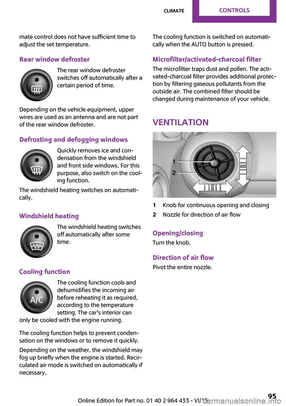
Ventilation1Knob for continuous opening and closing2Nozzle for direction of air flow
Opening/closingTurn the knob.
Direction of air flow Pivot the entire nozzle.
Seite 95ClimateCONTROLS95
Online Edition for Part no. 01 40 2 964 433 - VI/15
Page 101 of 223

The lighter can be removed as soon as it pops
back out.
WARNING
Contact with hot heating elements or the
hot socket of the cigarette lighter can cause
burns. Flammable materials can ignite if the
cigarette lighter falls down or is held against
the respective objects. There is risk of fire and
injuries. Hold the cigarette lighter on its handle.
Make sure that children do not use the ciga‐
rette lighter and do not burn themselves, e.g.
by carrying the remote control along when ex‐
iting the vehicle. ◀
Connecting electrical de‐
vices
The lighter socket can be used as a socket for
electrical equipment while the engine is run‐
ning or when the ignition is switched on. The
total load of all sockets must not exceed
140 watts at 12 volt.
Avoid damaging the sockets by attempting to
insert plugs of unsuitable shape or size.
CAUTION
Battery chargers for the vehicle battery
can work with high voltages and currents,
which means that the 12V on-board network
can be overloaded or damaged. There is risk of
property damage. Only connect battery charg‐
ers for the vehicle battery to the starting aid
terminals in the engine compartment. ◀
CAUTION
If metal objects fall into the socket, they
can cause a short circuit. There is risk of prop‐
erty damage. Replace the cigarette lighter or socket cover again after using the socket. ◀
Socket in the center console Remove the cover or lighter, refer to page 100,
from the socket.Socket in the rear
MINI Countryman
Take out the cover.
MINI Paceman
Take out the cover.
Socket in the cargo area
MINI Countryman
Take out the cover.
Seite 101Interior equipmentCONTROLS101
Online Edition for Part no. 01 40 2 964 433 - VI/15
Page 120 of 223
Saving fuelVehicle features and op‐tions
This chapter describes all standard, country-
specific and optional features offered with the
series. It also describes features that are not necessarily available in your car, e. g., due to
the selected options or country versions. This
also applies to safety-related functions and sys‐
tems.
When using the features and systems described
here, adhere to local regulations.
General information
Your vehicle contains advanced technology for
the reduction of fuel consumption and emis‐
sions.
Fuel consumption depends on a number of dif‐
ferent factors. The implementation of certain
measures, driving style and regular mainte‐
nance can have an influence on fuel consump‐
tion and on the environmental impact.
Remove unnecessary
cargo
Additional weight increases fuel consumption.
Remove attached partsfollowing use
Remove unneeded auxiliary mirrors, roof or
rear luggage racks after use.
Attached parts on the vehicle impair the aero‐
dynamics and increase the fuel consumption.Close both windows
Open windows causes higher air resistance and
thus increases fuel consumption.
Check the tire inflation
pressure regularly
Check and, if necessary, correct the tire infla‐
tion pressure, refer to page 154, at least twice
a month and before starting on a long trip.
Low tire inflation pressure increases rolling re‐
sistance and thus raises fuel consumption and
tire wear.
Drive away without de‐lay
Do not wait for the engine to warm-up while
the vehicle remains stationary. Start driving right away, but at moderate engine speeds.
This is the fastest way for the cold engine to
reach its operating temperature.
Look well ahead when
driving
Avoid unnecessary acceleration and braking. To
achieve this, maintain a suitable distance to the
vehicle driving ahead of you.
Driving smoothly and looking ahead reduces
fuel consumption.
Avoid high engine speeds
Use 1st gear to get the vehicle in motion. Be‐
ginning with 2nd gear, accelerate rapidly. WhenSeite 120DRIVING TIPSSaving fuel120
Online Edition for Part no. 01 40 2 964 433 - VI/15
Page 127 of 223
Setting the units of measure of the
computer and the language1.Switch on the radio ready state or the igni‐
tion.2. Press the button.3."CONFIG"4.▷"DIST": change the unit of measure for
the range.▷"LANG": select the language of the dis‐
play texts.▷"CONSMP": change the unit of measure
for the average fuel consumption.▷"TEMP": change the unit of measure for
the external temperature.5.Highlight the desired menu item and press
the button.6.Create the desired setting.
Computer
The following vehicle information can be call up
via the computer:
▷Average fuel consumption▷Average speed▷Range
Displaying information
1.Switch on the radio ready state or the igni‐
tion.2. Press the button.3."COMP"
Average fuel consumption
The average fuel consumption is calculated for
the time during which the engine is running.
To start calculation of the average fuel con‐
sumption:
1."CONSMP"2."RESET"The previous display is set to zero and the sys‐
tem begins recalculating the average fuel con‐
sumption.
Average speed
The average speed is calculated for the time
during which the engine is running.
To start calculation of the average speed:1."SPEED"2."RESET"
Estimated range
"RANGE"
The display shows the estimated distance that
can be still be driven on the remaining fuel,
taking into consideration the driving style over
the last 18 miles/30 km.
Radio
Listening to the radio
The radio is designed for reception in the FM
and AM wavebands.
1.Switch on the radio, refer to page 125.2. Press this button if necessary.3."TUNER"4."FM" or"AM"
Press the corresponding button repeatedly
until the desired waveband is displayed.▷FM: FM1, FM2, FMA▷AM: AM, AMA
Selecting a station
Settings are stored for the remote control cur‐
rently in use.
Next station
Press the button.
Seite 127Radio MINI Boost CDENTERTAINMENT127
Online Edition for Part no. 01 40 2 964 433 - VI/15
Page 131 of 223

Playback begins automatically.
Reading can take a few minutes with com‐
pressed audio files.
Starting the CD player
A CD is contained in the CD player.1.Switch on the car radio if necessary.2. Press the button.3."CD"
Skipping to another track
Press the button repeatedly until
the desired track is played.
With the right knob:
Turn the right knob until the desired track is
played back.
Fast forward/reverse
Hold the button down.
Tracks can be heard but are distorted.
Briefly playing and selecting a track
"SC"
All tracks are played briefly one after the other.
To interrupt the function and select a track:
"SC"
Random playback "RND"
To end random playback:
"RND"
Compressed audio files CD players can play back CDs with compressed
audio data: MP3 and WMA.
Selecting a track1."LIST"2.Select the desired directory using the right
knob.▷ : press the right knob to open a di‐
rectory.▷ : press the right knob to close a di‐
rectory.3.Select other directories if you wish.4.Highlight the desired track and press the
right knob.
You can scroll through the directories during
playback.
To change to the current track:
"CURR"
Displaying information on the track
Any information stored on the currently se‐
lected track can be displayed.
1."LIST"2."TRACK"
Ejecting a CD from the CD player
Press the button.
The CD emerges slightly from the CD drive.
Operational displays
▷"Insert CD"
The CD slot is empty.▷"Error CD"
The CD cannot be read or is not working.▷"Temp. CD"
Operating temperature is too high.Seite 131Radio MINI Boost CDENTERTAINMENT131
Online Edition for Part no. 01 40 2 964 433 - VI/15