brake light MINI COUNTRYMAN PACEMAN 2013 Owners Manual
[x] Cancel search | Manufacturer: MINI, Model Year: 2013, Model line: COUNTRYMAN PACEMAN, Model: MINI COUNTRYMAN PACEMAN 2013Pages: 275, PDF Size: 2.97 MB
Page 7 of 275
Notes
6
>Federal Emissions Performance Warranty
> California Emission Control System Limited
Warranty
Detailed information about these warranties is
listed in the Service and Warranty Information
Booklet for US models or in the Warranty and
Service Guide Booklet for Canadian models.
Your vehicle has been specifically adapted and
designed to meet the pa rticular operating con-
ditions and homologation requirements in your
country and continental region in order to
deliver the full driving pleasure while the vehicle
is operated under those conditions. If you wish
to operate your vehicle in another country or
region, you may be required to adapt your vehi-
cle to meet different prevailing operating condi-
tions and registration re quirements. You should
also be aware of any a pplicable warranty limita-
tions or exclusions for such country or region. In
such a case, please contact Customer Relations
for further information.
Maintenance
Maintain the vehicle regularly to sustain road
safety, operational reliab ility and the New Vehi-
cle Limited Warranty.
Specifications for required maintenance mea-
sures:
> MINI Maintenance System
> Service and Warranty Information Booklet
for US models
> Warranty and Service Guide Booklet for
Canadian models
If the vehicle is not ma intained according to
these specifications, this could result in serious
damage to the vehicle. Such damage is not cov-
ered by the MINI New Vehicle Limited Warranty.
Data memory
A variety of electronic components in your vehi-
cle include data storage devices, which store
technical information on the condition of your vehicle, events and errors, either temporarily or
permanently. In general,
this technical informa-
tion documents the condition of a component, a
module, a system or the surroundings:
> Operating conditions of system compo-
nents, e.g., fill levels.
> Status messages regarding the vehicle and
of its individual comp onents, such as wheel
rpm/vehicle speed, response delay, lateral
acceleration.
> Malfunctions and defects in the major sys-
tem components, such as the lights and
brakes.
> Responses of the vehicle in special driving
situations, such as the deployment of an air-
bag, the utilization of stability control sys-
tems.
> Environmental conditio ns, such as tempera-
ture.
These data are exclusively of a technical nature
and are used for the detection and correction of
errors, as well as the optimization of vehicle
functions. Motion profiles of traveled routes can
not be deduced from these data. If services are
required, such as repair services, service pro-
cesses, warranty claims an d quality assurance,
then this technical info rmation can be read out
by employees of service departments, including
the manufacturer, from the event and error data
storage devices by usin g special diagnostic
equipment. There, if necessary, you will receive
further information. Afte r remedying an error,
the information in the error memory is deleted
or progressively overwritten.
When using the vehicle, situations are conceiv-
able in which this techni cal data, in conjunction
with other information, su ch as accident reports,
vehicle damage, witness statements, etc. - pos-
sibly with the assistance of an expert - could be
traced to particular individuals. Additional func-
tions that are agreed upon contractually with
the customer, such as vehi cle tracking in case of
emergency, permit the transmission of certain
vehicle data from the vehicle.
00320051004F004C00510048000300280047004C0057004C005200510003
Page 14 of 275
CockpitAT A GLANCE
13
Indicator and warning
lamps
The concept
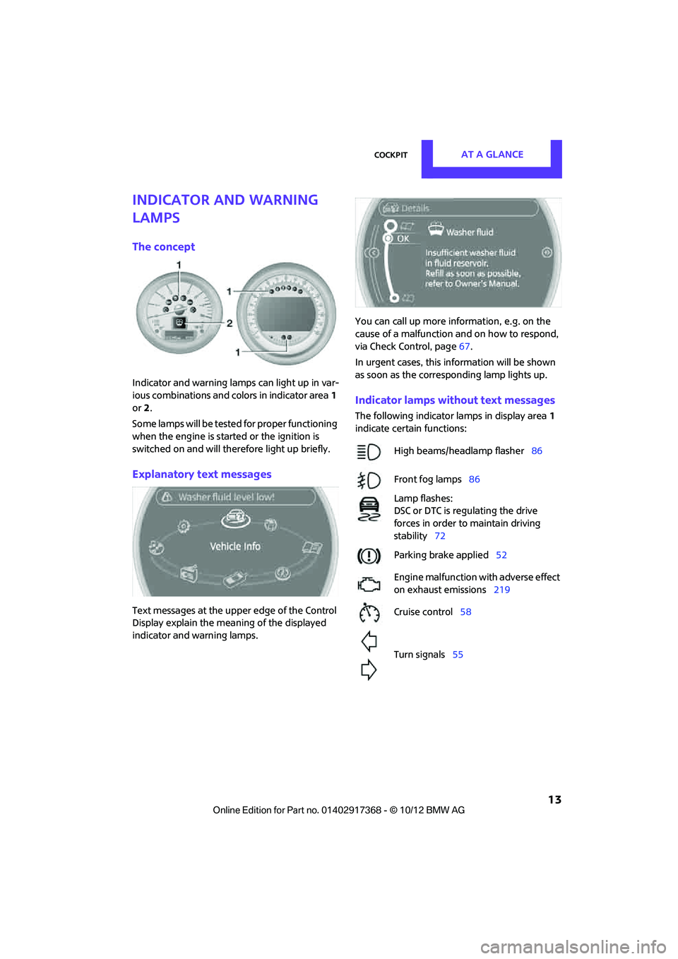
Indicator and warning lamps can light up in var-
ious combinations and colors in indicator area1
or 2.
Some lamps will be tested for proper functioning
when the engine is started or the ignition is
switched on and will therefore light up briefly.
Explanatory text messages
Text messages at the uppe r edge of the Control
Display explain the mean ing of the displayed
indicator and warning lamps. You can call up more information, e.g. on the
cause of a malfunction and on how to respond,
via Check Control, page
67.
In urgent cases, this information will be shown
as soon as the corresponding lamp lights up.
Indicator lamps without text messages
The following indicator lamps in display area 1
indicate certain functions:
High beams/headlamp flasher 86
Front fog lamps 86
Lamp flashes:
DSC or DTC is regulating the drive
forces in order to maintain driving
stability 72
Parking brake applied 52
Engine malfunction with adverse effect
on exhaust emissions 219
Cruise control 58
Turn signals 55
00320051004F004C00510048000300280047004C0057004C005200510003
Page 35 of 275
CONTROLSOpening and closing
34
Press the button again to lock the vehicle
again.<
Convenient opening with the remote control,
refer to page 28.
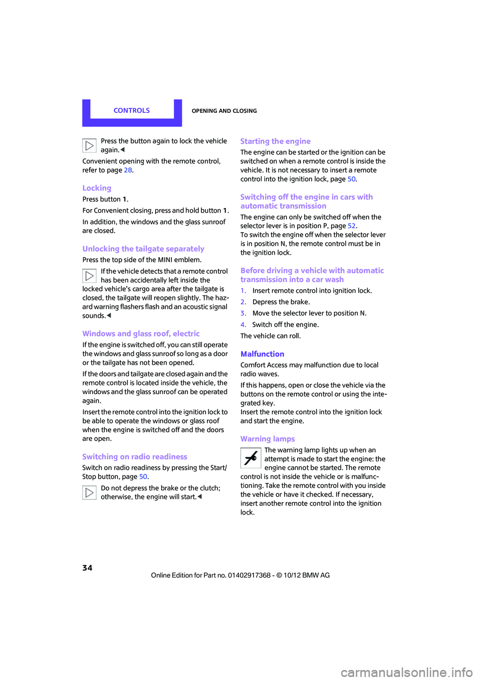
Locking
Press button 1.
For Convenient closing, press and hold button1.
In addition, the windows and the glass sunroof
are closed.
Unlocking the tailgate separately
Press the top side of the MINI emblem.
If the vehicle detects that a remote control
has been accidentally left inside the
locked vehicle's cargo area after the tailgate is
closed, the tailgate will reopen slightly. The haz-
ard warning flashers flash and an acoustic signal
sounds. <
Windows and glass roof, electric
If the engine is switched off, you can still operate
the windows and glass sunr oof so long as a door
or the tailgate has not been opened.
If the doors and tailgate are closed again and the
remote control is located inside the vehicle, the
windows and the glass sunroof can be operated
again.
Insert the remote control into the ignition lock to
be able to operate the windows or glass roof
when the engine is switched off and the doors
are open.
Switching on radio readiness
Switch on radio readiness by pressing the Start/
Stop button, page 50.
Do not depress the brake or the clutch;
otherwise, the engine will start. <
Starting the engine
The engine can be started or the ignition can be
switched on when a remote control is inside the
vehicle. It is not necessary to insert a remote
control into the ignition lock, page 50.
Switching off the engine in cars with
automatic transmission
The engine can only be switched off when the
selector lever is in position P, page 52.
To switch the engine off when the selector lever
is in position N, the remote control must be in
the ignition lock.
Before driving a vehicle with automatic
transmission into a car wash
1. Insert remote control into ignition lock.
2. Depress the brake.
3. Move the selector le ver to position N.
4. Switch off the engine.
The vehicle can roll.
Malfunction
Comfort Access may malf unction due to local
radio waves.
If this happens, open or close the vehicle via the
buttons on the remote control or using the inte-
grated key.
Insert the remote control into the ignition lock
and start the engine.
Warning lamps
The warning lamp lights up when an
attempt is made to start the engine: the
engine cannot be started. The remote
control is not inside the vehicle or is malfunc-
tioning. Take the remote control with you inside
the vehicle or have it checked. If necessary,
insert another remote co ntrol into the ignition
lock.
00320051004F004C00510048000300280047004C0057004C005200510003
Page 51 of 275
CONTROLSDriving
50
Driving
Vehicle equipment
In this chapter, all production, country, and
optional equipment that is offered in the model
range is described. Equipment is also described
that is not available because of, for example,
selected options or coun try version. This also
applies to safety relate d functions and systems.
Ignition lock
Inserting the key into the ignition lock
Insert the key all the way into the ignition lock.
Radio readiness
Individual electrical consumers can operate.
Removing the key from the ignition lock
Press in the key briefly. It is ejected slightly.
At the same time:
>The ignition is switched off if it was on
beforehand.
Automatic transmission
The key can only be removed if the selector lever
is in position P: interlock.
Start/Stop button
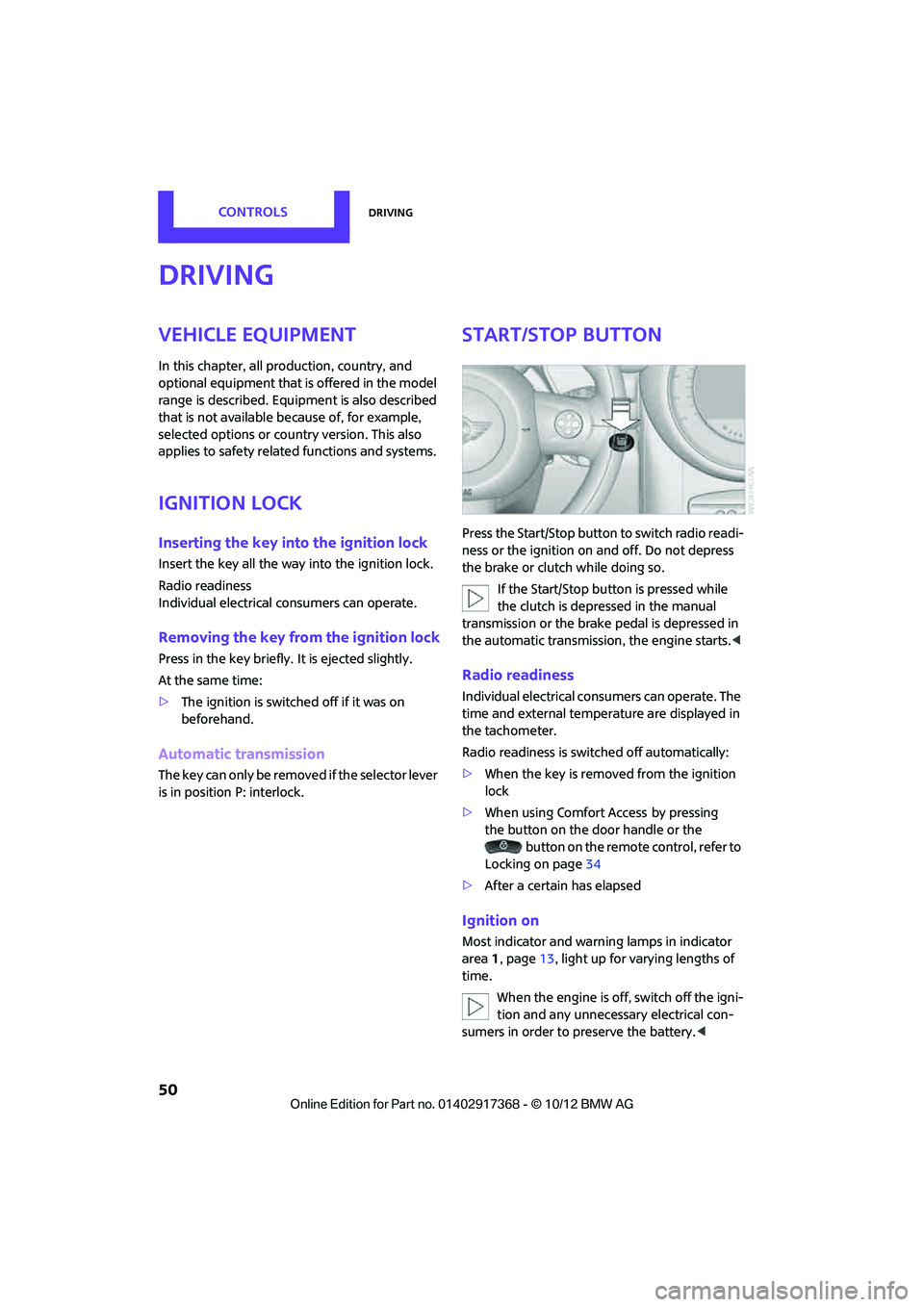
Press the Start/Stop button to switch radio readi-
ness or the ignition on and off. Do not depress
the brake or clutch while doing so.
If the Start/Stop button is pressed while
the clutch is depressed in the manual
transmission or the brake pedal is depressed in
the automatic transmission, the engine starts. <
Radio readiness
Individual electrical consumers can operate. The
time and external temperature are displayed in
the tachometer.
Radio readiness is switched off automatically:
>When the key is removed from the ignition
lock
> When using Comfort Access
by pressing
the button on the door handle or the
button on the remote control, refer to
Locking on page 34
> After a certain has elapsed
Ignition on
Most indicator and warn ing lamps in indicator
area 1, page 13, light up for varying lengths of
time.
When the engine is off, switch off the igni-
tion and any unnecessary electrical con-
sumers in order to preserve the battery. <
00320051004F004C00510048000300280047004C0057004C005200510003
Page 53 of 275
CONTROLSDriving
52
Automatic transmission
1.With the car at a stop, move the selector
lever to position P.
2. Press the Start/Stop button.
3. Forcefully apply the parking brake.
Before driving into a car wash
By following these steps, the vehicle is able to
roll:
1.Place the remote control, even with Comfort
Access, in the ignition lock.
2. Depress the brake.
3. Move the selector lever to position N.
4. Switch off the engine.
Parking brake
The parking brake is primarily intended to pre-
vent the vehicle from rolling while parked; it
brakes the rear wheels.
In addition, follow the instructions on page 51
under Switching off the engine.
Applying
The lever locks in position automatically.
Releasing
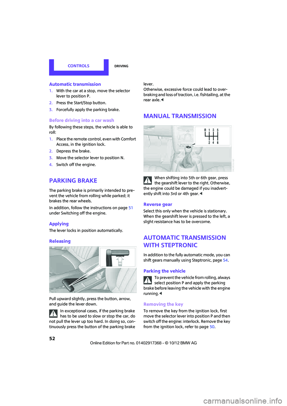
Pull upward slightly, pr ess the button, arrow,
and guide the lever down.
In exceptional cases, if the parking brake
has to be used to slow or stop the car, do
not pull the lever up too hard. In doing so, con-
tinuously press the button of the parking brake lever.
Otherwise, excessive force could lead to over-
braking and loss of traction
, i.e. fishtailing, at the
rear axle. <
Manual transmission
When shifting into 5t h or 6th gear, press
the gearshift lever to the right. Otherwise,
the engine could be damaged if you inadvert-
ently shift into 3rd or 4th gear. <
Reverse gear
Select this only when the vehicle is stationary.
When the gearshift lever is pressed to the left, a
slight resistance has to be overcome.
Automatic transmission
with Steptronic
In addition to the fully automatic mode, you can
shift gears manually using Steptronic, page 54.
Parking the vehicle
To prevent the vehicle from rolling, always
select position P and apply the parking
brake before leaving the vehicle with the engine
running. <
Removing the key
To remove the key from the ignition lock, first
move the selector lever into position P and then
switch off the engine: in terlock. Remove the key
from the ignition lock, refer to page 50.
00320051004F004C00510048000300280047004C0057004C005200510003
Page 56 of 275
DrivingCONTROLS
55
The extractor hook is in the onboard
document holder or in the pouch for
the tire-changing set, page 232.<
4. Pull the loop up.
5. Move the selector le ver into the desired
position by pressing the button on the front
of the selector lever.
Before manually unlocking the selector
lever lock, firmly set the parking brake to
prevent the vehicle from rolling away. <
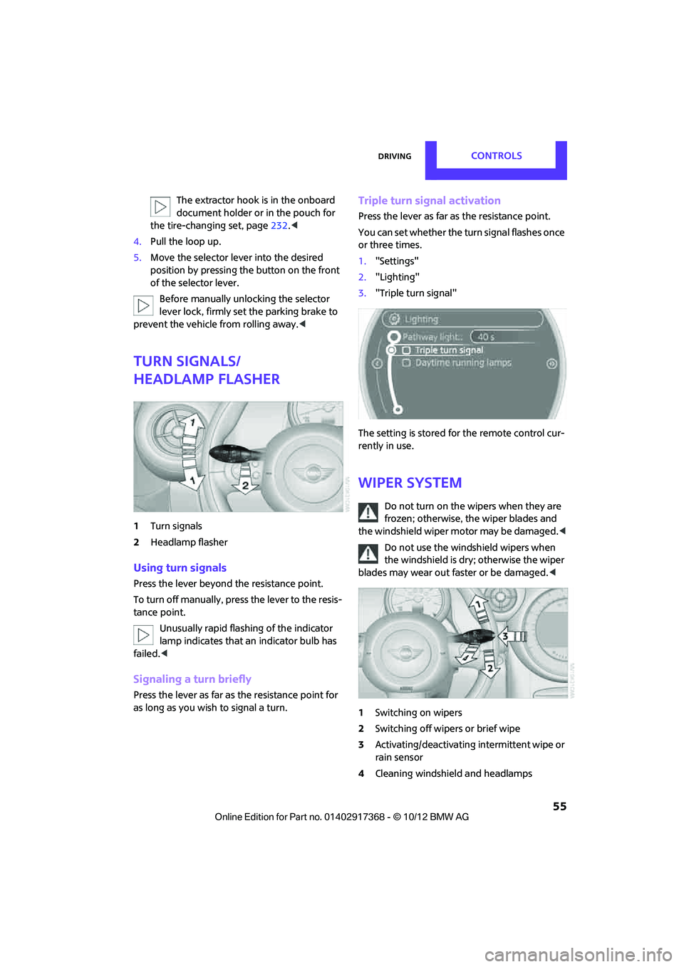
Turn signals/
headlamp flasher
1Turn signals
2 Headlamp flasher
Using turn signals
Press the lever beyond the resistance point.
To turn off manually, pre ss the lever to the resis-
tance point.
Unusually rapid flashi ng of the indicator
lamp indicates that an indicator bulb has
failed. <
Signaling a turn briefly
Press the lever as far as the resistance point for
as long as you wish to signal a turn.
Triple turn signal activation
Press the lever as far as the resistance point.
You can set whether the turn signal flashes once
or three times.
1. "Settings"
2. "Lighting"
3. "Triple turn signal"
The setting is stored for the remote control cur-
rently in use.
Wiper system
Do not turn on the wipers when they are
frozen; otherwise, the wiper blades and
the windshield wiper motor may be damaged. <
Do not use the windshield wipers when
the windshield is dry; otherwise the wiper
blades may wear out faster or be damaged. <
1 Switching on wipers
2 Switching off wipers or brief wipe
3 Activating/deactivating intermittent wipe or
rain sensor
4 Cleaning windshield and headlamps
00320051004F004C00510048000300280047004C0057004C005200510003
Page 73 of 275
CONTROLSTechnology for driving comfort and safety
72
enter the sensors' blind spots before or after a
continuous audible signal is given. Higher, pro-
truding objects, such as wall ledges, may not be
detectable. Therefore, always drive cautiously;
otherwise, there is a risk of personal injury or
property damage. Loud sound sources outside
or inside the car can drown out the PDC signal. <
Driving stability control
systems
Your MINI has a number of systems that help to
maintain the vehicle's stability even in adverse
driving conditions.
The laws of physics cannot be repealed,
even with driving stability control systems.
An appropriate driving style always remains the
responsibility of the driver. Therefore do not
reduce the additional safe t y m a r g i n b y e n g a g i n g
in hazardous driving thereby running the risk of
an accident. <
Antilock Brake System ABS
ABS prevents locking of the wheels during brak-
ing. Safe steering response is maintained even
during full braking. Active safety is thus
increased.
Braking safely, refer to page 105.
ABS is operational every time you start the
engine.
Cornering Brake Control CBC
Driving stability and stee ring characteristics are
further enhanced while braking in turns or dur-
ing a lane change.
Electronic brake-force distribution EBV
The system controls the brake pressure in the
rear wheels to ensure stable braking behavior.
Brake Assist
Rapidly depressing the brake causes this system
to automatically develop maximum braking force. Thus, the system helps keep braking dis-
tance to a minimum. At the same time, all the
benefits provided by ABS are exploited.
Do not reduce the pressure on the brake for the
duration of the full braking application.
Dynamic Stability Control DSC
The concept
DSC prevents the driving wheels from losing
traction when you pull away from rest or accel-
erate.
DSC also detect
s unstable driving conditions
such as when the vehicle's rear end fishtails or
the vehicle is sliding on its front wheels. In these
cases, DSC helps the ve hicle maintain a safe
course within physical limits by reducing engine
output and through braking actions at the indi-
vidual wheels.
Every time that the engine is started, DSC is
ready to operate.
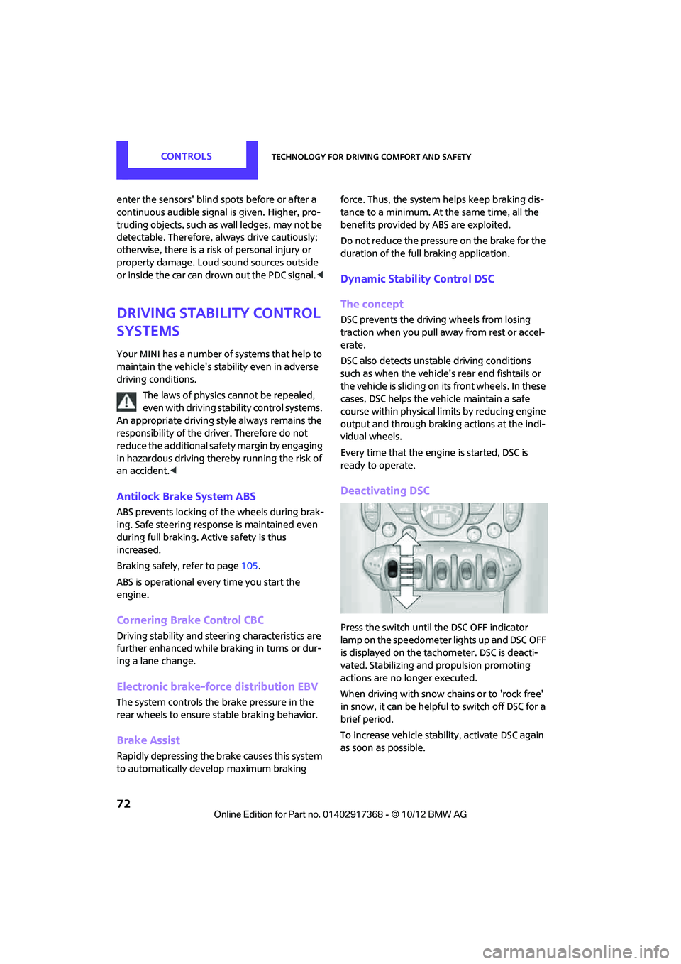
Deactivating DSC
Press the switch until the DSC OFF indicator
lamp on the speedometer lights up and DSC OFF
is displayed on the tachometer. DSC is deacti-
vated. Stabilizing and propulsion promoting
actions are no longer executed.
When driving with snow chains or to 'rock free'
in snow, it can be helpfu l to switch off DSC for a
brief period.
To increase vehicle stabil ity, activate DSC again
as soon as possible.
00320051004F004C00510048000300280047004C0057004C005200510003
Page 75 of 275
CONTROLSTechnology for driving comfort and safety
74
Deactivating both DTC and DSC
Press the switch for at least 3 seconds; the indi-
cator lamp DSC OFF on the speedometer comes
on and DSC OFF is displayed on the tachometer.
The Dynamic Traction Control DTC and Dynamic
Stability Control DSC are both deactivated. There
will be no more stabilizing interventions.
Interventions (differential lock) in braking occur
to improve propulsion when drive wheels are
rotating unevenly, even when DSC is deacti-
vated.
Activating DSC
Press the switch again: the indicator lamps in the
display elements go out.
Hill Assist
Hill Assist aids you in co mfortably driving off on
inclines. It is not necessary to use the parking
brake for this.
1. Hold the MINI with the brake.
2. Release the brake and immediately drive
off.
Hill Assist holds the car in place for approx.
2 seconds after the brake is released. Depending on the load and gradient, the
vehicle can roll backwa rd slightly during
this period. After you release the brake, immedi-
ately start driving since the Hill Assist only holds
the vehicle for about 2 seconds, and it will start
to roll backward. <
ALL4 all-wheel drive system
ALL4 is the all-wheel driv e system of your MINI.
The combined effects of ALL4 and DSC further
optimize the traction and dynamic driving char-
acteristics. The ALL4 all- wheel drive system vari-
ably distributes the drive force to the front and
rear axle depending on the driving situation and
prevailing road conditions.
Sport button
Pressing the button causes your MINI to respond
even more sportily.
> Engine responds more spontaneously to
movements of the accelerator.
> Steering response is more direct.
> Cooper S, John Cooper Works: the engine
sounds more sporty in coasting mode.
With automatic transmission:
> More rapid gear shifting in Sport program.
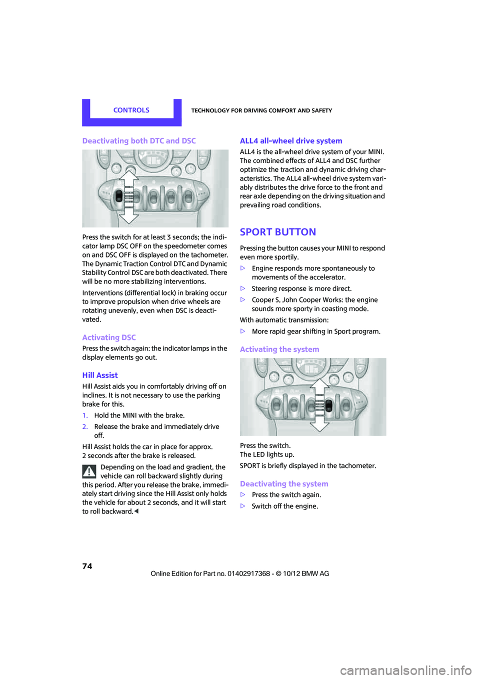
Activating the system
Press the switch.
The LED lights up.
SPORT is briefly displayed in the tachometer.
Deactivating the system
>Press the switch again.
> Switch off the engine.
00320051004F004C00510048000300280047004C0057004C005200510003
Page 107 of 275
DRIVING TIPSThings to remember when driving
106
Hills
To prevent overheating and the resulting
reduced efficiency of the brake system,
drive long or steep downhill gradients in the
gear in which the least braking is required. Even
light but consistent brake pressure can lead to
high temperatures, brake wear and possibly
even brake failure. <
You can increase the engine's braking effect by
shifting down, all the way to first gear if neces-
sary. This strategy helps you avoid placing
excessive loads on the brake system. Downshift-
ing in manual mode of the automatic transmis-
sion, page 54.
Never drive with the clutch held down,
with the transmission in neutral or with
the engine switched off; otherwise, engine brak-
ing action will not be present or there will be no
power assistance to the brakes or steering.
Never allow floor mats, carpets or any other
objects to protrude into the area around the
pedals; otherwise, pedal function could be
impaired. <
Corrosion on brake rotors
When the vehicle is driven only occasionally,
during extended periods when the vehicle is not
used at all, and in op erating conditions where
brake applications are less frequent, there is an
increased tendency for corrosion to form on
rotors, while contaminants accumulate on the
brake pads. This occurs because the minimum
pressure which must be exerted by the pads
during brake applications to clean the rotors is
not reached.
Should corrosion form on the brake rotors, the
brakes will tend to respond with a pulsating
effect that even extended application will fail to
cure.
When the vehicle is parked
Condensation forms while the automatic climate
control is in operation, and then exits under the
vehicle. Traces of condensed water under the
vehicle are therefore normal. In the MINI Cooper S, the coolant pump may
continue to run for some time after the engine is
switched off. This will
generate noise in the
engine compartment.
Cargo loading
To avoid loading the tires beyond their
approved carrying capacity, never over-
load the vehicle. Overloading can lead to over-
heating and increases the rate at which damage
develops inside the tires. The ultimate result can
assume the form of a sudden blowout. <
Avoid fluid spills in the cargo area as they
could damage the vehicle. <
Expanding cargo area
Cargo area cover
Do not place any objects on the cover;
otherwise, they could endanger the car's
occupants, e.g. in the case of braking or sudden
swerving, or they may damage the cover. <
When you open the tailgate, the roll-up cover is
raised.
To load bulky luggage, the cover can be
removed.
1. Unhook the lift straps from the tailgate.
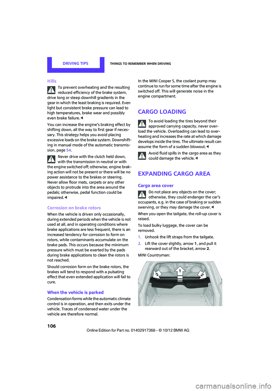
2. Lift the cover slightly, arrow 1, and pull it
rearward out of the bracket, arrow 2.
MINI Countryman:
00320051004F004C00510048000300280047004C0057004C005200510003
Page 115 of 275
DRIVING TIPSThings to remember when driving
114
Avoid high engine speeds
Use first gear only for driving off. In second and
higher gears, accelerate smoothly to a suitable
engine and road speed. In doing so, avoid high
engine speeds and shift up early.
When you reach your desired traveling speed,
shift to the highest suitable gear and drive at
constant speed.
As a rule: driving at lo w engine speeds lowers
fuel consumption and reduces wear.
Coasting
When approaching a red traffic light, take your
foot off the accelerator and let the car roll to a
stop in the highest gear possible.
On a downhill gradient, take your foot off the
accelerator and let the vehicle coast in a suitable
gear.
Fuel supply is shut off automatically when the
vehicle is coasting.
Switch off the engine during lengthy
stops
Switch off the engine when stopping for lengthy
periods, e.g. at traffic li ghts, railroad crossings or
in traffic jams.
Switch off any features that are not
currently required
Features such as air conditioning, seat heaters
and the rear window defroster require a great
deal of energy and result in greater fuel con-
sumption, especially in city driving and during
Stop & Go operation. For this reason, switch off
these features if they are not really needed.
Have the vehicle serviced
Have your vehicle servic ed regularly to achieve
good economy and a long vehicle life. The man-
ufacturer of your MINI recommends having the
vehicle serviced by a MINI dealer. Also note the
MINI Maintenance System, page 218.
Driving on poor roads
Your MINI with ALL4 drive is at home on any
type of street or road. It combines an all-wheel
drive system with the ad vantages of a normal
passenger car.
Do not drive on unpa ved terrain, as other-
wise the vehicle may be damaged. <
When you are driving on poor roads, there are a
few points which you shou ld strictly observe for
your own safety, for that of your passengers,
and for the safety of the vehicle:
> Familiarize yourself with the vehicle before
beginning to drive and do not take risks
under any circumstances.
> Adapt your speed to road conditions. The
steeper and rougher the road surface is, the
lower the speed should be.
> When driving on very steep uphill or down-
hill grades, make sure in advance that the
engine oil and coolant levels are close to the
maximum mark, refer to page 215.
> While driving, watch carefully for obstacles
such as rocks or holes. Try to avoid these
obstacles whenever possible.
> Make sure that the un dercarriage does not
touch the ground, for example on hilltops
and bumpy roads. The ground clearance of
the vehicle is a maximum of approx. 6.0 in/
15 cm. Please note that the ground clear-
ance can vary depending on loading and the
driving conditions of the vehicle.
> Only drive through road surface water up to
a maximum water depth of 1 ft/30 cm and
only at walking speed ; do not remain sta-
tionary.
> After driving through water at low speed,
lightly press the brake pedal several times to
dry the brakes and to prevent the braking
effect from being reduced by wetness.
00320051004F004C00510048000300280047004C0057004C005200510003