trip computer MINI COUNTRYMAN PACEMAN 2013 Owners Manual
[x] Cancel search | Manufacturer: MINI, Model Year: 2013, Model line: COUNTRYMAN PACEMAN, Model: MINI COUNTRYMAN PACEMAN 2013Pages: 275, PDF Size: 2.97 MB
Page 12 of 275
CockpitAT A GLANCE
11
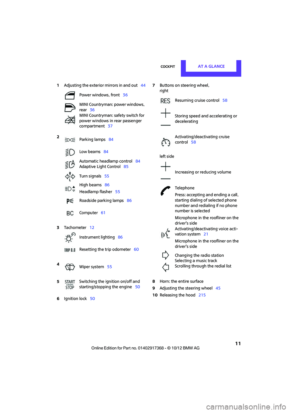
1Adjusting the exterior mirrors in and out44
6 Ignition lock 50 7
Buttons on steering wheel,
right
left side
8 Horn: the entire surface
9 Adjusting the steering wheel 45
10 Releasing the hood 215
Power windows, front
36
MINI Countryman: power windows,
rear 36
MINI Countryman: safety switch for
power windows in rear passenger
compartment 37
2 Parking lamps 84
Low beams 84
Automatic headlamp control 84
Adaptive Light Control 85
Turn signals 55
High beams 86
Headlamp flasher 55
Roadside parking lamps 86
Computer 61
3 Tachometer 12
Instrument lighting 86
Resetting the trip odometer 60
4 Wiper system 55
5 Switching the ignition on/off and
starting/stopping the engine
50
Resuming cruise control58
Storing speed and accelerating or
decelerating
Activating/deactivating cruise
control 58
Increasing or reducing volume
Telephone
Press: accepting and ending a call,
starting dialing of selected phone
number and redialing if no phone
number is selected
Microphone in the roofliner on the
driver's side
Activating/deactivating voice acti-
vation system 21
Microphone in the roofliner on the
driver's side
Changing the radio station
Selecting a music track
Scrolling through the redial list
00320051004F004C00510048000300280047004C0057004C005200510003
Page 13 of 275

AT A GLANCECockpit
12
Displays
1Tachometer 60
with indicator and warning lamps 13
2 Display for
>Current vehicle speed 60
> Indicator and warning lamps 13
3 Resetting the trip odometer 604
Display for
>Position of automatic transmission 52
> Computer 61
> Date of next scheduled service, and
remaining distance to be driven 64
> Odometer and trip odometer 60
> Settings and information 62
> Personal Prof ile settings26
5 Instrument lighting 86
6 Speedometer
with indicator and warning lamps 13
7 Control Display 17
8 Fuel gauge 60
00320051004F004C00510048000300280047004C0057004C005200510003
Page 28 of 275
Opening and closingCONTROLS
27
Personal Profile settings
For more information on specific settings, refer
to the specified pages.
> Response of the central locking system
when the car is being unlocked 27
> Automatic locking of the vehicle 30
> Triple turn signal activation 55
> Settings for the displays on the onboard
computer, in the speedometer and in the
tachometer:
>12 h/24 h mode of the clock 66
> Date format 67
> Brightness of the Control Display 70
> Language on the Control Display 69
> Units of measure for fuel consumption,
distance covered/re maining distances
and temperature 64
> Light settings:
>Pathway lighting 85
> Daytime running lights 85
> Automatic climate control: activating/deac-
tivating the AUTO program, setting the tem-
perature, air volume and air distribution 90
> Entertainment:
>Audio volume 141
> Tone control 141
Central lock ing system
The concept
The central locking system is ready for operation
whenever the driver's door is closed.
The system simultaneously engages and
releases the locks on the following:
>Doors
> Tailgate
> Fuel filler flap
Operating from outside
>Via the remote control
> Using the door lock
> In cars with Comfor t Access, via the door
handles on the driver's and passenger's
sides
The anti-theft system is also operated at the
same time. It prevents the doors from being
unlocked using the lock buttons or door han-
dles. The remote control can also be used to
switch the welcome lamps, the interior light, and
the ambient lighting on and off. The alarm sys-
tem
is also activated or deactivated, page 32.
Operating from inside
Switch/button for central locking system,
page30.
In the event of a sufficiently severe accident, the
central locking system unlocks automatically. In
addition, the hazard warning flashers and inte-
rior lamps come on.
Opening and closing:
from outside
Persons or animals in a parked vehicle
could lock the doors from the inside. Take
the key with you when you leave the vehicle so
that the vehicle can be opened from the out-
side. <
Using the remote control
Unlocking
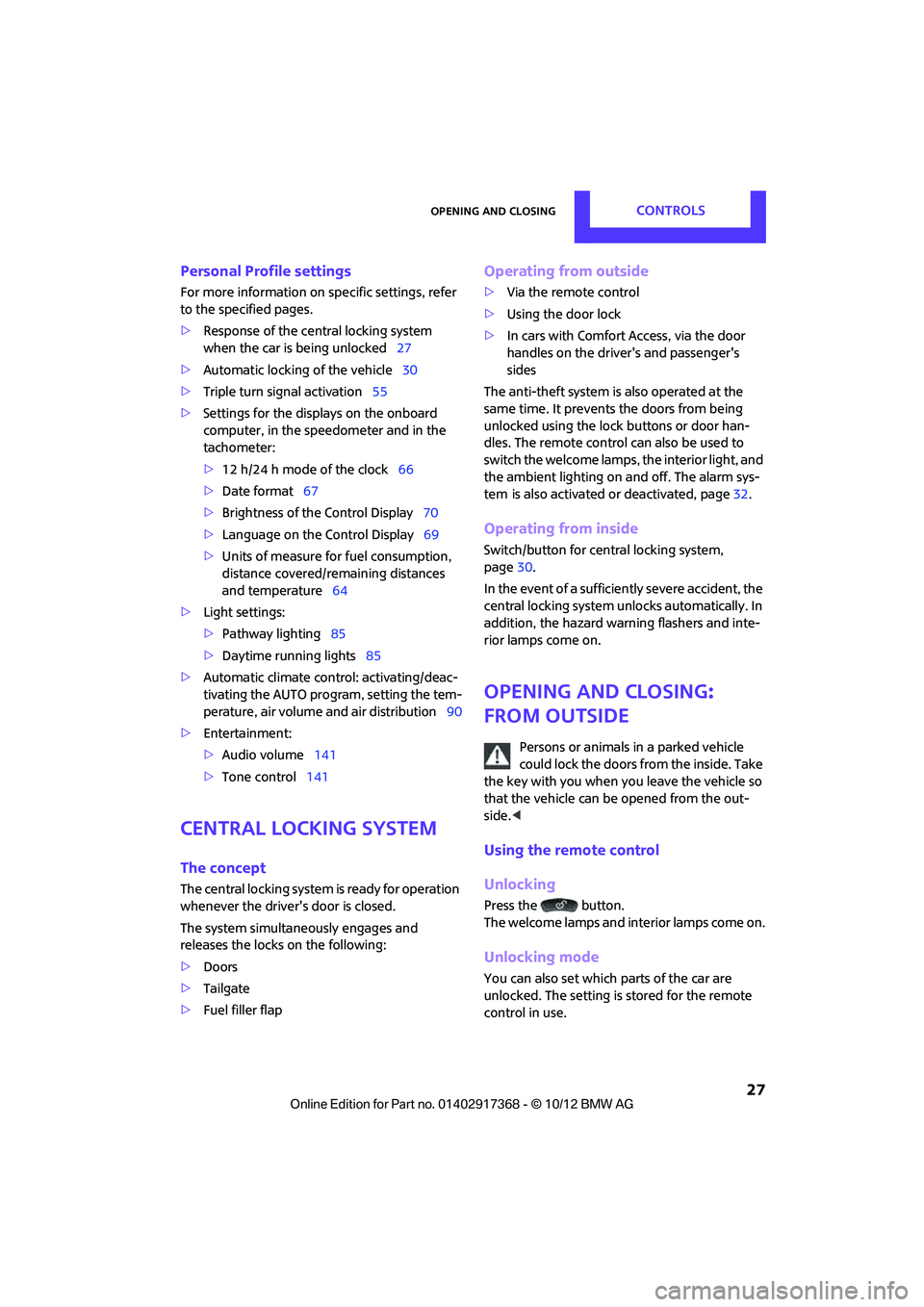
Press the button.
The welcome lamps and interior lamps come on.
Unlocking mode
You can also set which parts of the car are
unlocked. The setting is stored for the remote
control in use.
00320051004F004C00510048000300280047004C0057004C005200510003
Page 62 of 275

Controls overviewCONTROLS
61
The following information is displayed sequen-
tially:
> Trip odometer
> Time
> External temperature
Trip odometer
To display trip recorder:
Briefly press button 3.
Resetting the trip odometer:
While the trip recorder is displayed and the igni-
tion is switched on, press button 3.
Time
To set time, see page 66.
External temperature, external
temperature warning
When the displayed temperature sinks to
approx. +37 7/+3 6, a signal sounds and a
warning lamp lights up. There is an increased
risk of black ice.
Even at temperatures above +37 7/+3 6
ice can form. Therefore, drive carefully,
e.g. on bridges and sections of road in the
shade; otherwise, there is an increased accident
risk. <
Units of measure
Select the respective units of measure, miles or
km for the odometer as well as 7 or 6 for the
external temperature, page 64.
Computer
Displays in the tachometer
Press the button in the turn signal lever repeat-
edly to call up variou s items of information.
The following information is displayed sequen-
tially:
> Cruising range
> Average fuel consumption
> Current fuel consumption
> Average speed
To set the corresponding units of measure, refer
to Units of measure on page 64.
Cruising range
Displays the estimated cruising range available
with the remaining fuel. The range is calculated
on the basis of the way the car has been driven
over the last 18 miles/30 km and the amount of
fuel currently in the tank.
If the range displayed is less than
30 miles/50 km, be sure to refuel; other-
wise, engine functions are not guaranteed and
damage could occur.<
Average fuel consumption
Calculated for the time the engine has been run-
ning.
With the trip computer, page 62, you can have
the average fuel consumption for another trip
displayed.
00320051004F004C00510048000300280047004C0057004C005200510003
Page 63 of 275
CONTROLSControls overview
62
To reset average fuel consumption: press the
button in the turn signal lever for approx.
2seconds.
Current fuel consumption
Displays the current fuel consumption to allow
you to see whether your current driving style is
conducive to fuel economy with minimum
exhaust emissions.
Average speed
Periods with the vehicle parked and the engine
switched off are not included in the calculations
of average speed.
With the trip computer, page 62, you can have
the average speed for another trip displayed.
To reset average speed: press the button in the
turn signal lever for approx. 2 seconds.
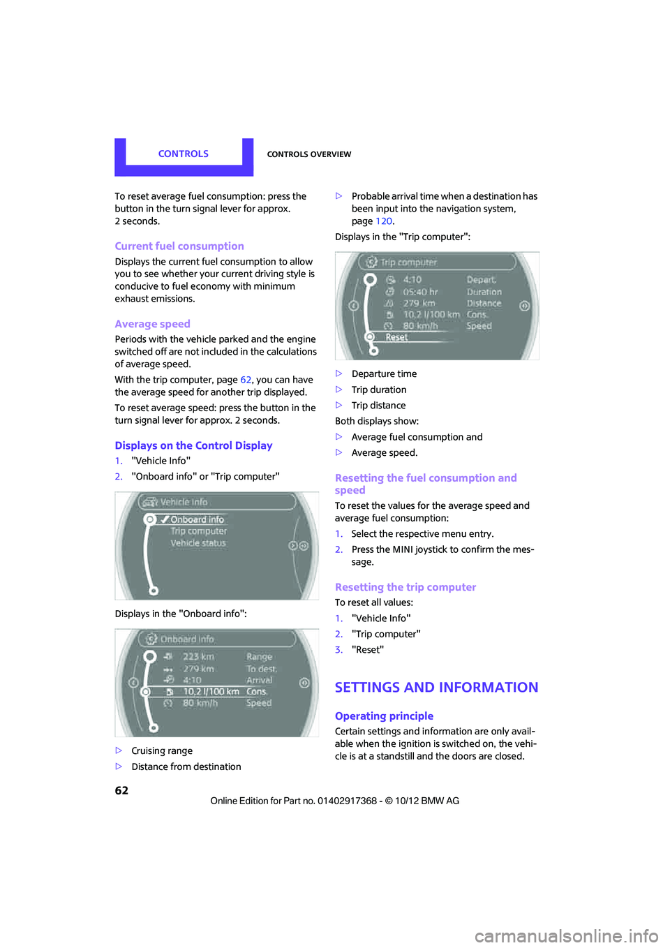
Displays on the Control Display
1. "Vehicle Info"
2. "Onboard info" or "Trip computer"
Displays in the "Onboard info":
> Cruising range
> Distance from destination >
Probable arrival time when a destination has
been input into the navigation system,
page 120.
Displays in the "Trip computer":
> Departure time
> Trip duration
> Trip distance
Both displays show:
> Average fuel consumption and
> Average speed.
Resetting the fuel consumption and
speed
To reset the values for the average speed and
average fuel consumption:
1.Select the respective menu entry.
2. Press the MINI joystick to confirm the mes-
sage.
Resetting the trip computer
To reset all values:
1."Vehicle Info"
2. "Trip computer"
3. "Reset"
Settings and information
Operating principle
Certain settings and information are only avail-
able when the ignition is switched on, the vehi-
cle is at a standstill and the doors are closed.
00320051004F004C00510048000300280047004C0057004C005200510003
Page 79 of 275
CONTROLSTechnology for driving comfort and safety
78
Gray wheels
The system cannot detect a puncture.
Reasons for this may be:
>TPM is being reset.
> Interference from systems or devices with
the same transmission frequency.
> Malfunction.
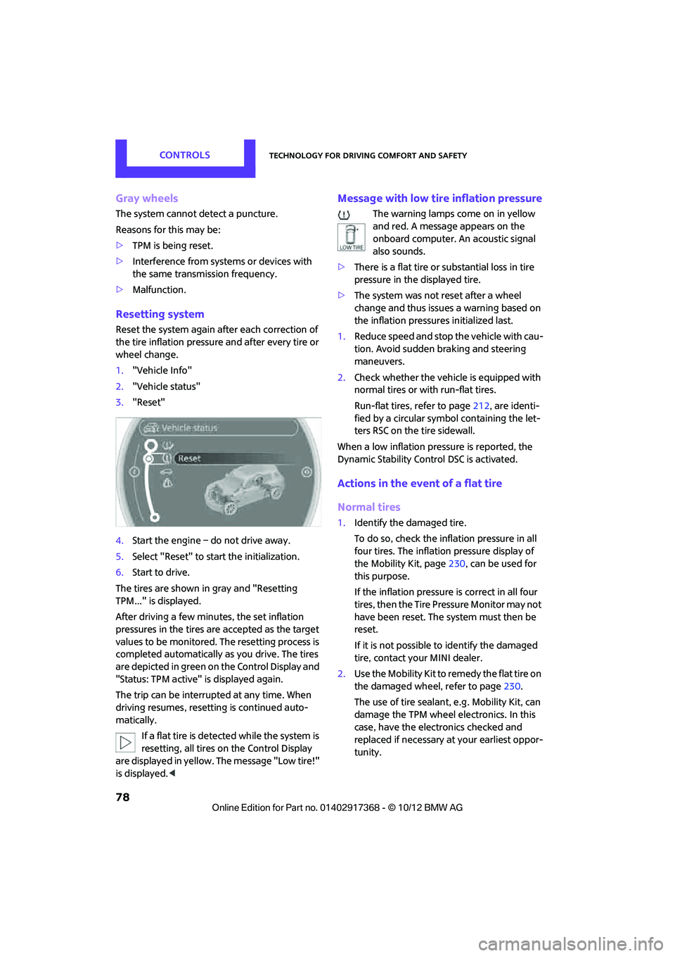
Resetting system
Reset the system again af ter each correction of
the tire inflation pressure and after every tire or
wheel change.
1. "Vehicle Info"
2. "Vehicle status"
3. "Reset"
4. Start the engine – do not drive away.
5. Select "Reset" to start the initialization.
6. Start to drive.
The tires are shown in gray and "Resetting
TPM..." is displayed.
After driving a few minutes, the set inflation
pressures in the tires are accepted as the target
values to be monitored. The resetting process is
completed automatically as you drive. The tires
are depicted in green on the Control Display and
"Status: TPM active" is displayed again.
The trip can be interrupted at any time. When
driving resumes, resett ing is continued auto-
matically.
If a flat tire is detected while the system is
resetting, all tires on the Control Display
are displayed in yellow. The message "Low tire!"
is displayed. <
Message with low tire inflation pressure
The warning lamps come on in yellow
and red. A message appears on the
onboard computer. An acoustic signal
also sounds.
> There is a flat tire or substantial loss in tire
pressure in the displayed tire.
> The system was not reset after a wheel
change and thus issues a warning based on
the inflation pressures initialized last.
1. Reduce speed and stop the vehicle with cau-
tion. Avoid sudden braking and steering
maneuvers.
2. Check whether the vehicle is equipped with
normal tires or with run-flat tires.
Run-flat tires, refer to page 212, are identi-
fied by a circular symbol containing the let-
ters RSC on the tire sidewall.
When a low inflation pressure is reported, the
Dynamic Stability Cont rol DSC is activated.
Actions in the event of a flat tire
Normal tires
1.Identify the damaged tire.
To do so, check the inflation pressure in all
four tires. The inflatio n pressure display of
the Mobility Kit, page 230, can be used for
this purpose.
If the inflation pressure is correct in all four
tires, then the Tire Pressure Monitor may not
have been reset. The system must then be
reset.
If it is not possible to identify the damaged
tire, contact your MINI dealer.
2. Use the Mobility Kit to remedy the flat tire on
the damaged wheel, refer to page 230.
The use of tire sealant, e.g. Mobility Kit, can
damage the TPM wheel electronics. In this
case, have the electronics checked and
replaced if necessary at your earliest oppor-
tunity.
00320051004F004C00510048000300280047004C0057004C005200510003
Page 119 of 275
NAVIGATIONNavigation system
118
Navigation system
Vehicle equipment
In this chapter, all production, country, and
optional equipment that is offered in the model
range is described. Equipment is also described
that is not available because of, for example,
selected options or coun try version. This also
applies to safety relate d functions and systems.
General information
The navigation system can determine the pre-
cise position of the vehicle, with the aid of satel-
lites and vehicle sensors, and can reliably guide
you to every entered destination.
Enter data only with the vehicle station-
ary, and always give priority to the appli-
cable traffic regulations in the event of any con-
tradiction between traffic and road conditions
and the instructions issu ed by the navigation
system. Failure to take to this precaution can
place you in violation of the law and put vehicle
occupants and other ro ad users in danger.<
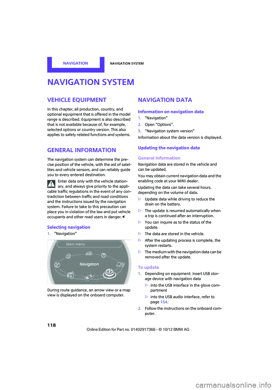
Selecting navigation
1."Navigation"
During route guidance, an arrow view or a map
view is displayed on the onboard computer.
Navigation data
Information on navigation data
1. "Navigation"
2. Open "Options".
3. "Navigation system version"
Information about the data version is displayed.
Updating the navigation data
General information
Navigation data are stored in the vehicle and
can be updated.
You may obtain current navigation data and the
enabling code at your MINI dealer.
Updating the data can take several hours,
depending on the volume of data.
> Update data while driving to reduce the
drain on the battery.
> The update is resumed automatically when
a trip is continued after an interruption.
> You can inquire as to the status of the
update.
> The data are stored in the vehicle.
> After the updating process is complete, the
system restarts.
> The medium with the na vigation data can be
removed after the update.
To update
1. Depending on equipment: insert USB stor-
age device with navigation data
>into the USB interface in the glove com-
partment
> into the USB audio interface, refer to
page 154.
2. Follow the instructions on the onboard com-
puter.
00320051004F004C00510048000300280047004C0057004C005200510003
Page 128 of 275
Destination entryNAVIGATION
127
Similar-sounding towns/cities that cannot
be differentiated by the system are com-
piled in a separate list and displayed as a town/
city followed by three dots.
If necessary, select this entry with {Yes }. Then
select the desired city/town in this list. <
The town/city can also be selected from the list
via the onboard computer:
Turn the MINI joystick until the destination is
selected, and press the MINI joystick.
Entering a street or intersection
The street or intersection is entered in the same
way as the town/city.
Entering house number
Depending on the data in the navigation system,
house numbers up to the number 2,000 can be
entered:
Starting route guidance
Route guidance starts immediately.
Adding further intermediate
destinations
Further intermediate dest inations can be added.
Saving destination
The destination is automati cally added to the list
of the last destinations.
Planning a trip with
intermediate
destinations
New trip
Various intermediate destinations can be
entered for a trip. The tr ip destination must be
entered first, refer to Destination input,
page 120.
Entering intermed iate destinations
A maximum of 30 intermed iate destinations can
be entered for one trip.
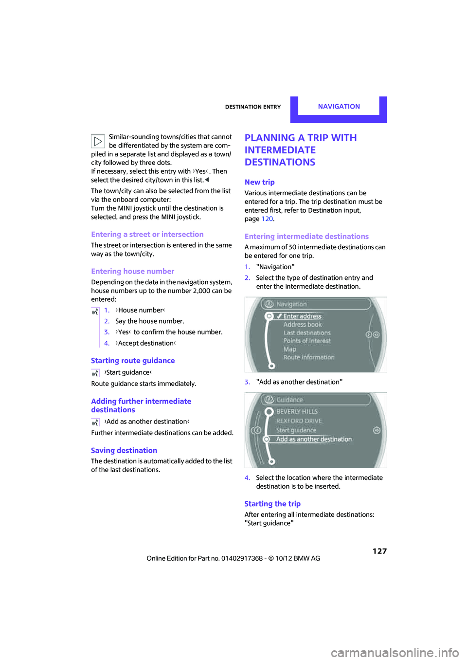
1. "Navigation"
2. Select the type of destination entry and
enter the intermed iate destination.
3. "Add as another destination"
4. Select the location where the intermediate
destination is to be inserted.
Starting the trip
After entering all inte rmediate destinations:
"Start guidance"
1.
{House number }
2. Say the house number.
3. {Yes } to confirm the house number.
4. {Accept destination }
{ Start guidance }
{ Add as another destination }
00320051004F004C00510048000300280047004C0057004C005200510003
Page 130 of 275
Route guidanceNAVIGATION
129
Route guidance
Starting route guidance
1."Navigation"
2. "Enter address"
3. Select the destination.
4. "Accept destination"
5. "Start guidance"
> The route is displayed on the onboard com-
puter.
> The distance to the destination/intermedi-
ate destination and th e estimated time of
arrival are displayed in the map view.
> The arrow display is displayed on the
onboard computer, if so desired.
Terminating route
guidance
In the arrow or map view
1."Navigation"
2. "Map"
3. Select the symbol.
4. "Stop guidance"
Continuing route
guidance
If the destination was not reached during the
last trip, route guid ance can be resumed.
"Resume guidance"
Route criteria
General information
> You can influence the calculated route by
selecting certain criteria.
> Route criteria can be changed during desti-
nation input and during route guidance.
> Street types are part of the navigation data
and are taken into account in route plan-
ning, e.g. avoiding highways.
> The proposed route can differ from personal
experience.
> The settings are stored for the remote con-
trol currently in use.
> Route guidance with traffic information,
refer to page 135.
Changing route criteria
1."Navigation"
2. "Map"
3. "Route preference"
4. Selecting a criterion:
> "Fast route": time-optimized route
through a combination of the least possi-
ble distance and stre tches of road that
allow rapid driving.
> "Efficient route": optimized combi-
nation of the fastest and shortest possi-
ble route.
> "Short route": shor t distance without
taking time into account.
00320051004F004C00510048000300280047004C0057004C005200510003
Page 259 of 275
REFERENCEShort commands for the voice activation system
258
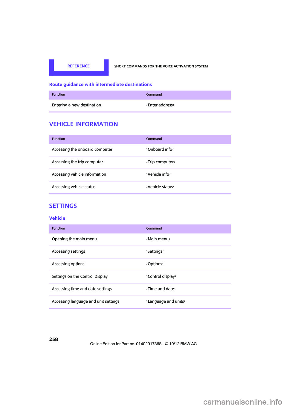
Route guidance with intermediate destinations
Vehicle information
Settings
Vehicle
FunctionCommand
Entering a new destination {Enter address}
FunctionCommand
Accessing the onboard computer {Onboard info }
Accessing the trip computer {Trip computer}
Accessing vehicle information {Vehicle info}
Accessing vehicle status {Vehicle status }
FunctionCommand
Opening the main menu {Main menu}
Accessing settings {Settings }
Accessing options {Options}
Settings on the Control Display {Control display }
Accessing time and date settings {Time and date }
Accessing language and unit settings {Language and units }
00320051004F004C00510048000300280047004C0057004C005200510003