service indicator MINI Coupe 2013 Owner's Manual
[x] Cancel search | Manufacturer: MINI, Model Year: 2013, Model line: Coupe, Model: MINI Coupe 2013Pages: 292, PDF Size: 7.02 MB
Page 14 of 292

Displays1Tachometer 75
with indicator and warning lamps 152Display for▷Current speed 74▷Indicator/warning lamps 153Resetting the trip odometer 744Display for▷Automatic transmission position 71▷Computer 75▷Service requirements 81▷Odometer and trip odometer 74▷Flat Tire Monitor 93▷Tire Pressure Monitor 93▷Settings and information 77▷Personal Profile settings 315Instrument lighting 886Speedometer with indicator and warning
lamps 157Control Display 188Fuel gauge 75Seite 14At a glanceCockpit14
Online Edition for Part no. 01 40 2 919 017 - II/13
Page 39 of 292
To switch off the engine with the selector lever
in position N, the remote control must be in‐
serted in the ignition lock.
Before driving a vehicle with automatic
transmission into a car wash1.Insert the remote control into the ignition
switch.2.Depress the brake pedal.3.Move the selector lever to position N.4.Switch the engine off.
The vehicle can roll.
Malfunction The Comfort Access functions can be disturbed
by local radio waves, such as by a mobile
phone in the immediate vicinity of the remote
control or when a mobile phone is being
charged in the vehicle.
If this occurs, open or close the vehicle using
the buttons on the remote control or use the
integrated key in the door lock.
To start the engine afterward, insert the remote
control into the ignition switch.
Warning lamps The warning lamp in the instrument
cluster lights up when you attempt to
start the engine: the engine cannot be
started.
The remote control is not in the vehicle or has a
malfunction. Take the remote control with you
inside the vehicle or have it checked. If neces‐
sary, insert another remote control into the ig‐
nition switch.
The warning lamp in the instrument
cluster lights up while the engine is run‐
ning: the remote control is no longer in‐
side the vehicle.
After switching off the engine, the engine can
only be started again within approx. 10 sec‐
onds if no door has been opened.
The indicator lamp lights up and a mes‐
sage appears on the Control Display: re‐
place the remote control battery.
Replacing the battery
The remote control for Comfort Access contains
a battery that will need to be replaced from
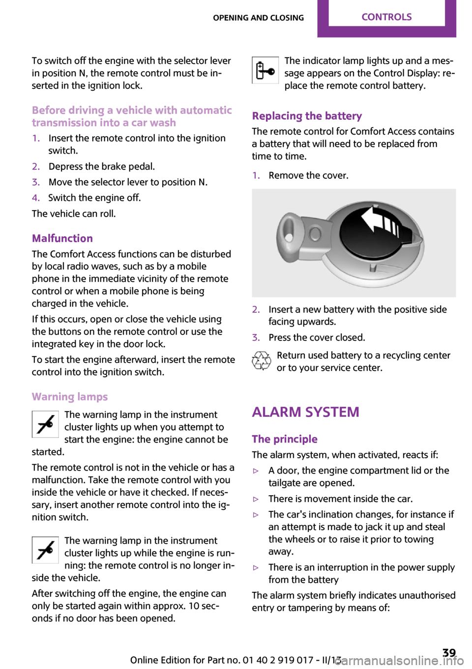
time to time.1.Remove the cover.2.Insert a new battery with the positive side
facing upwards.3.Press the cover closed.
Return used battery to a recycling center
or to your service center.
Alarm system
The principle The alarm system, when activated, reacts if:
▷A door, the engine compartment lid or the
tailgate are opened.▷There is movement inside the car.▷The car's inclination changes, for instance if
an attempt is made to jack it up and steal
the wheels or to raise it prior to towing
away.▷There is an interruption in the power supply
from the battery
The alarm system briefly indicates unauthorised
entry or tampering by means of:
Seite 39Opening and closingControls39
Online Edition for Part no. 01 40 2 919 017 - II/13
Page 56 of 292

Unbuckling the belt1.Hold the belt firmly.2.Press the red button in the belt buckle.3.Guide the belt back into its reel.
MINI Convertible: rear belt guide
When fastening the safety belts on the rear
seats, ensure that the belt guide loop, arrow, is
closed.
Safety belt reminder for driver's seat
and front passenger seat
The indicator lamps light up and a sig‐
nal sounds. In addition, a message ap‐
pears on the Control Display. Check
whether the safety belt has been fas‐
tened correctly.
Damage to safety belts
In the case of strain caused by accidents or
damage:
Have the safety belts, including the safety belt
tensioners, replaced and have the belt anchors
checked.
Checking and replacing safety belts
Have the work performed only by your
service center; otherwise, it cannot be ensured
that this safety feature will function properly. ◀
Head restraints
Correctly set head restraint
A correctly adjusted head restraint reduces the
risk of spinal injury in the event of an accident.
Adjusting the head restraint
Correctly adjust the head restraints of all
occupied seats; otherwise, there is an increased
risk of injury in an accident. ◀
Height Adjust the head restraint so that its center is
approx. at ear level.
Distance
Adjust the distance so that the head restraint is as close as possible to the back of the head.
Height adjustment
To raise: pull.
To lower: press the button, arrow 1, and push
the head restraint down.
Removing
Only remove the head restraint if no one will be
sitting in the seat in question.
1.Pull upward as far as possible.2.Press the button, arrow 1, and pull the
head restraint out completely.
To remove the head restraint, fold the backrest
forward if necessary.
Seite 56ControlsAdjusting56
Online Edition for Part no. 01 40 2 919 017 - II/13
Page 91 of 292
▷Never modify either the individual compo‐
nents or the wiring in the airbag system.
This also applies to steering wheel covers,
the dashboard, the seats, the roof pillars
and the sides of the headliner. ◀
Even when all instructions are followed closely,
injury from contact with the airbags cannot be
ruled out in certain situations.
The ignition and inflation noise may lead to
short-term and, in most cases, temporary hear‐
ing impairment in sensitive individuals.
In the case of a malfunction, deactivation
and after triggering of the airbags
Do not touch the individual components imme‐
diately after the system has been triggered;
otherwise, there is the danger of burns.
Only have the airbags checked, repaired or dis‐
mantled and the airbag generator scrapped by
your service center or a workshop that has the
necessary authorization for handling explo‐
sives.
Non-professional attempts to service the sys‐
tem could lead to failure in an emergency or
undesired triggering of the airbag, either of
which could result in injury. ◀
Warning notices and information about the air‐
bags can also be found on the sun visors.
Automatic deactivation of the front
passenger airbags
The occupation of the seat is detected by eval‐
uating the impression on the occupied seat sur‐
face of the front passenger seat.
The front and side airbags on the front passen‐
ger side are activated or deactivated accord‐
ingly by the system.
The indicator lamp above the interior rearview
mirror, refer to page 92, shows the current
status of the front passenger airbags, deacti‐
vated or activated.
Leave feet in the footwell
Make sure that the front passenger keeps
his or her feet in the footwell; otherwise, the
front passenger airbags may not function prop‐
erly. ◀
Child restraint fixing system in the front
passenger seat
Before transporting a child on the front passen‐
ger seat, read the safety and operating instruc‐
tions under Transporting children safely, refer
to page 59.◀
Malfunction of the automatic deactivation system
When transporting older children and adults,
the front passenger airbags may be deactivated
in certain sitting positions. In this case, the indi‐
cator lamp for the front passenger airbags
lights up.
In this case, change the sitting position so that
the front passenger airbags are activated and
the indicator lamp goes out.
If it is not possible to activate the airbags, have
the person sit in the rear.
To make sure that occupation of the seat cush‐
ion can be detected correctly:▷Do not attach seat covers, seat cushion
padding, ball mats, or other items to the
front passenger seat unless they are specifi‐
cally recommended by the manufacturer of
your MINI.▷Do not place any objects on the front pas‐
senger seat.▷Do not place objects under the seat that
could press against the seat from below.Seite 91SafetyControls91
Online Edition for Part no. 01 40 2 919 017 - II/13
Page 230 of 292

Minimum tread depth
Wear indicators in the tread base are distrib‐
uted around the circumference of the tire and
are marked on the tire sidewall with TWI, Tread
Wear Indicator. When the tire tread has been
worn down to the wear indicators, a tread has
reached a depth of 0.063 in/1.6 mm.
Tire damage
General information Inspect your tires often for damage, foreign ob‐
jects lodged in the tread, and tread wear.
Notes
Driving over rough or damaged road surfaces,
as well as debris, curbs and other obstacles can
cause serious damage to wheels, tires and sus‐
pension parts. This is more likely to occur with
low-profile tires, which provide less cushioning
between the wheel and the road. Be careful to
avoid road hazards and reduce your speed, es‐
pecially if your vehicle is equipped with low-
profile tires.
Indications of tire damage or other vehicle de‐
fects:
▷Unusual vibrations during driving.▷Unusual handling such as a strong ten‐
dency to pull to the left or right.
Damage can be caused by driving over curbs,
road damage and similar situations.
In case of tire damage
If there are indications of tire damage, re‐
duce your speed immediately and have the
wheels and tires checked right away; other‐
wise, there is the increased risk of an accident.
Drive carefully to the next service center or tire
shop.
If necessary, have the vehicle towed.
Otherwise, tire damage can present a life-
threatening hazard to vehicle occupants and
other road users. ◀
Repair of tire damage
For safety reasons, the manufacturer of
your vehicle recommends that you do not have
damaged tires repaired; they should be re‐
placed. Otherwise, damage can occur as a re‐
sult. ◀
Tire age RecommendationFor several reasons, among other things be‐
cause of beginning brittleness, the manufac‐
turer of your MINI recommends mounting new
tires at the latest after six years, regardless of
the actual wear.
Manufacture date The date of manufacture of the tires is specified
in the tire label:
DOT … 1012: the tire was manufactured in
week 10 of 2012.Seite 230MobilityWheels and tires230
Online Edition for Part no. 01 40 2 919 017 - II/13
Page 252 of 292

3.Mount the new wheel.4.Screw in at least two bolts crosswise.5.Screw in the remaining lug bolts.6.Fully tighten all lug bolts in a diagonal pat‐
tern.7.Lower the vehicle.8.Remove the jack.
Retightening the lug bolts
Retighten the lug bolts diagonally.
Checking that the lug bolts are tight
Always have the lug bolts checked with a
calibrated torque wrench as soon as possible to
ensure that they are tightened to the specified
torque. Otherwise, incorrectly tightened lug
bolts are a hidden safety risk. ◀
The tightening torque equals
103.3 lb ft/140 Nm.
Replace the defective tire as soon as possible
and have the new wheel balanced.
Vehicle battery Maintenance
The battery is maintenance-free, i.e., the elec‐
trolyte will last for the life of the battery in tem‐
perate climate conditions.
The service center will be happy to answer any
questions on the battery.
Battery replacement Use approved vehicle batteries
Only use vehicle batteries that have been
approved for your vehicle by the manufacturer;
otherwise, the vehicle could be damaged and
systems or functions may not be fully availa‐
ble. ◀
Have the vehicle battery registered by the serv‐
ice center after it is replaced to ensure that all comfort functions are available without restric‐
tions and that any associated Check Control
messages are no longer displayed.
Charging the battery
Note Do not connect the charger to the socket
Do not connect the battery charger to the
socket installed in the vehicle at the factory as
this could damage the battery. ◀
Only charge the battery in the vehicle when the
engine is switched off. Connections, refer to
page 254.
General information Ensure that the battery is sufficiently charged to
achieve the full battery life.
It may be necessary to charge the battery in
the following cases:▷When the vehicle is frequently used to
travel short distances.▷When the vehicle has not been driven for
more than one month.
Power failure
After a temporary power failure, some equip‐
ment will be restricted in its use and will need
to be reinitialized. In addition, certain individual
settings will be lost and must be updated:
▷Time and date: the values must be up‐
dated, refer to page 79.▷Radio: the stations need to be stored again,
refer to page 161.▷Onboard monitor: full functionality will be
restored after some time.
Indicator/warning lamps
Lights up red: the vehicle battery is no
longer being charged. Alternator mal‐
function.
Switch off all unnecessary electrical consumers.
Have the battery checked immediately.
Seite 252MobilityReplacing components252
Online Edition for Part no. 01 40 2 919 017 - II/13
Page 253 of 292

Lights up yellow: the battery charge
level is very low, the battery is old, or it
is not securely connected.
Charge the battery by taking a long drive or us‐
ing an external charger. If the indicators appear
again, have the battery checked as soon as
possible.
Disposing of old batteries Have used batteries disposed of by the
service center after they are replaced or
take them to a recycling center.
Maintain the battery in an upright position for
transport and storage. Secure the battery so
that it does not tip over during transport.
Fuses Replacing fuses
Never attempt to repair a blown fuse and
do not replace a defective fuse with a substi‐ tute of another color or amperage rating; this
could lead to a circuit overload, ultimately re‐
sulting in a fire in the vehicle. ◀
Fuses should be replaced by the service center.
Information on the fuses can be found on the
inside of the covers.
In the engine compartment
Opening the cover
Press the snap lock.
In interior
On the right side of the footwell.
Opening the cover
Push out at the recess.
Seite 253Replacing componentsMobility253
Online Edition for Part no. 01 40 2 919 017 - II/13
Page 280 of 292
Everything from A to ZIndexA
ABS, Antilock Brake Sys‐ tem 101
Acoustic signal, refer to Check Control 82
Activated charcoal filter with automatic climate con‐
trol 112
Adaptive Light Control 87
Additional telephone 192
Additives, engine oil 239
Airbags 90
Airbags, indicator/warning light 92
Air circulation, refer to Recir‐ culated air mode 109, 111
Air conditioner 108
Air conditioning 108
Air conditioning mode– Air conditioner 108– Automatic climate con‐
trol 110
Air distribution
– Automatic 111– Individual 109– Manual 109, 112
Air drying, refer to Cooling
function 112
Air flow rate 108, 111
Air pressure, refer to Tire infla‐ tion pressure 222
Air supply
– Air conditioner 108– Automatic climate con‐
trol 110
Alarm system 39
Always Open Timer 77
AM/FM station 160
Ambient lighting 89
Announcement, navigation,
refer to Spoken instruc‐
tions 149
Antifreeze, washer fluid 69
Antilock Brake System, ABS 101
Anti-slip control, refer to Dy‐ namic Stability Control
DSC 101
Anti-theft protection 31
Appointments 208
Approved engine oils 239
Ashtray 114
Assistance, roadside 254
Assistance when driving off, refer to Hill drive-off assis‐
tant 103
Assistance with starting en‐ gine, refer to Jump-start‐
ing 254
Audio playback 169
Audio playback, Blue‐ tooth 175
Automatic– Air distribution 111– Air flow rate 111
Automatic car wash 259
Automatic climate control
– Automatic air distribu‐
tion 111
Automatic, cruise control 105
Automatic headlamp con‐ trol 85
Automatic rear spoiler 103
Automatic transmission with
Steptronic
– Kickdown 71– Overriding selector lever
lock 72
AUTO program with auto‐
matic climate control 111
AUX-IN port 171
Average fuel consumption 76
Average fuel consumption– Setting the units 78
Average speed 76
Average speed, refer to Com‐ puter 75
B Backrest curvature, refer to Lumbar support 54
Backrests, refer to Seats 53
Backup lamps, bulb replace‐ ment 247
Balance 158
Bass 158
Battery
– Disposal 39– Remote control 30
Battery, refer to Vehicle bat‐
tery 252
Battery replacement
– Remote control 39
Belts, refer to Safety belts 55
Belt tensioners, refer to Safety belts 55
Bi-xenon headlamps 245
Black and white map dis‐ play 152
Blower, refer to Air flow rate 108, 111
Bluetooth audio 175
Bluetooth connection, activat‐ ing/deactivating 183, 193
Bluetooth hands-free sys‐ tem 182
Brake assistant 101
Brake discs, breaking in 124
Brake fluid, refer to Service re‐ quirements 81
Seite 280ReferenceEverything from A to Z280
Online Edition for Part no. 01 40 2 919 017 - II/13
Page 282 of 292
Cooling function, switching onand off 112
Cooling, maximum 111
Cornering Brake Control, CBC 101
Corrosion on brake discs 126
Cradle for telephone or mobile phone, refer to Snap-in
adapter 202
Cruise control 105
Cupholders 114
Current fuel consumption 76
Current location, storing 140
Curve lights, refer to Adaptive Light Control 87
Cylinders, number of, refer to Engine data 266
D
Dashboard lighting, refer to Instrument lighting 88
Dashboard, refer to Cock‐ pit 12
Dashboard, refer to Dis‐ plays 14
Data, technical 266
Date– Date format 80– Setting 79
Daytime running lights 86
Decorative trim, care 262
Defogging windows 109
Defroster
– Rear window 109, 112
Defrosting windows 109
Defrost setting, refer to De‐ frosting windows 109
Destination entry via the ad‐ dress book 140
Destination guidance with in‐ termediate destinations 145
Destination input, naviga‐ tion 138
Digital radio 161
Dip stick, engine oil 238
Directional indicators, refer to
Turn signals 67
Displacement, refer to Engine data 266
Display lighting, refer to In‐ strument lighting 88
Displays 14
Displays and controls 12
Displays, care 263
Displays, cleaning 263
Displays, refer to Instrument cluster 14
Disposal– Remote control battery 39
Distance warning, refer to
Park Distance Control
PDC 106
Door key, refer to Remote control with integrated
key 30
Door lock 34
Door lock, confirmation sig‐ nals 33
Doors, manual operation 35
Doors, unlocking and locking
– Confirmation signals 33– From the inside 35– From the outside 32
DOT Quality Grades 228
Drive-off assistant, refer to Hill drive-off assistant 103
Driving notes, breaking in 124
Driving off on hills, refer to Hill drive-off assistant 103
Driving stability control sys‐ tems 101
Driving tips, refer to Driving notes 124
Dry air, refer to Cooling func‐ tion 112
DSC Dynamic Stability Con‐ trol 101
DTC Dynamic Traction Con‐ trol 102
DTMF suffix dialing 187, 199
Dynamic destination guid‐
ance 154
Dynamic Stability Control DSC 101
Dynamic Traction Control DTC 102
E
Electrical convertible top 42
Electrical malfunction– Convertible top 44, 51– Door lock 35– Fuel filler flap 218– Tailgate 36
Electronic brake-force distri‐
bution 101
Electronic Stability Program ESP, refer to Dynamic Stabil‐
ity Control DSC 101
Emergency activation
– Automatic transmission, re‐
fer to Overriding selector
lever lock 72
Emergency activation, refer to
Manual activation
– Tailgate 36
Emergency operation, fuel
filler flap, unlocking man‐
ually 218
Emergency operation, refer to
Manual operation
– Convertible top 44, 51– Door lock 35
Energy, saving, refer to Saving
fuel 131
Engine, breaking in 124
Engine compartment 236
Engine oil, adding 238
Engine oil, additives, refer to Approved engine oils 239
Engine oil, alternative oil types 239
Engine oil change intervals, refer to Service require‐
ments 81
Engine oil, dip stick 238
Seite 282ReferenceEverything from A to Z282
Online Edition for Part no. 01 40 2 919 017 - II/13
Page 287 of 292
Rear fog lamps, indicatorlamp 15
Rear lamps, refer to Tail lamps 247
Rear spoiler 103
Rearview mirror, refer to Mir‐ rors 57
Rear window de‐ froster 109, 112
Recirculated air mode 109, 111
Recommended tire brands 231
Redialing 188, 200
Releasing, refer to Unlock‐ ing 38
Remaining range for service, refer to Service require‐
ments 81
Remaining range, refer to Range 76
Reminders 210
Remote control– Battery replacement 39– Comfort Access 37– Malfunctions 33, 39– Tailgate 33
Remote control, removing
from the ignition lock 64
Remote control, service data 241
Remote inquiry 187, 199
Replacement remote con‐ trol 30
Replacing wheels/tires 231
Reporting safety defects 9
Reserve warning, refer to Fuel gauge 75
Reservoir for washer fluid, re‐ fer to Washer fluid reser‐
voir 69
Restraining systems
– Refer to Safety belts 55
Restraint systems for chil‐
dren 59
Retreaded tires 231
Reverse gear, manual trans‐
mission 70
Road, avoiding 147
Road detour 147
Roadside Assistance 254
Roadside parking lamp, bulb replacement 246
Roadside parking lamps 86
RON gasoline quality 220
RON, refer to Fuel quality 220
Route 148
Route criteria, route 147
Route, displaying 148
Route section, bypassing 148
RPM, refer to Engine data 266
Rubber seals, care 262
Run-flat tires 232
Run-flat tires– Flat tire 94
Run-flat tires, tire inflation
pressure 222
Running lights, refer to Park‐ ing lamps/low beams 85
S Safe braking 126
Safety 7
Safety belts 55
Safety belts
– Damage 56
Safety belts, care 262
Safety belts, indicator/warning lamp 56
Safety belts, reminder 56
Safety systems
– Safety belts 55
Safety systems, airbags 90
Satellite radio 162
Saving fuel 131
Scale, changing during navi‐ gation 151
Screen, see Control Display 18
Seat adjustment
– Manual 53
Seat belts
– Refer to Safety belts 55Seat heating 55
Seats– Adjusting 53– Heating 55– Sitting safely 53
Selector lever, automatic
transmission with Step‐
tronic 71
Selector lever lock, overrid‐ ing 72
Selector lever lock, refer to Changing selector lever posi‐
tions, Shiftlock 71
Selector lever positions, auto‐ matic transmission with
Steptronic 71
Service and warranty 7
Service data in the remote control 241
Service interval display, refer to Condition Based Service
CBS 241
Service interval display, refer to Service requirements 81
Service requirements 81
Service requirements, CBS Condition Based Service 241
Settings
– Changing on the Control Dis‐
play 80– Language 80
Settings and information 77
Settings, configuring, refer to Personal Profile 31
Setting the clock, 12h/24h for‐ mat 79
Shifting
– Automatic transmission with
Steptronic 71
Shifting, manual transmis‐
sion 70
Shift lever
– Automatic transmission with
Steptronic 71
Shift paddles on the steering
wheel 72
Seite 287Everything from A to ZReference287
Online Edition for Part no. 01 40 2 919 017 - II/13