display MINI Coupe 2014 (Mini Connected) Owner's Guide
[x] Cancel search | Manufacturer: MINI, Model Year: 2014, Model line: Coupe, Model: MINI Coupe 2014Pages: 288, PDF Size: 6.72 MB
Page 80 of 288
3."Date:"4.Turn the MINI joystick until the desired day
is displayed and press the MINI joystick.5.Make the necessary settings for the month
and year.
The date is stored.
Setting the date format
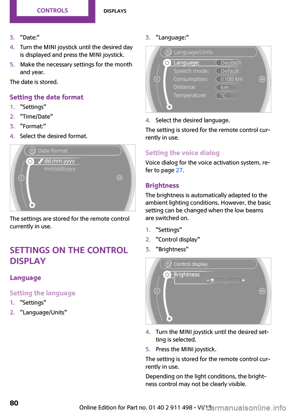
1."Settings"2."Time/Date"3."Format:"4.Select the desired format.
The settings are stored for the remote control
currently in use.
Settings on the Control Display
Language
Setting the language
1."Settings"2."Language/Units"3."Language:"4.Select the desired language.
The setting is stored for the remote control cur‐
rently in use.
Setting the voice dialog Voice dialog for the voice activation system, re‐
fer to page 27.
Brightness
The brightness is automatically adapted to the
ambient lighting conditions. However, the basic
setting can be changed when the low beams
are switched on.
1."Settings"2."Control display"3."Brightness"4.Turn the MINI joystick until the desired set‐
ting is selected.5.Press the MINI joystick.
The setting is stored for the remote control cur‐
rently in use.
Depending on the light conditions, the bright‐
ness control may not be clearly visible.
Seite 80ControlsDisplays80
Online Edition for Part no. 01 40 2 911 498 - VI/13
Page 81 of 288
Service requirements
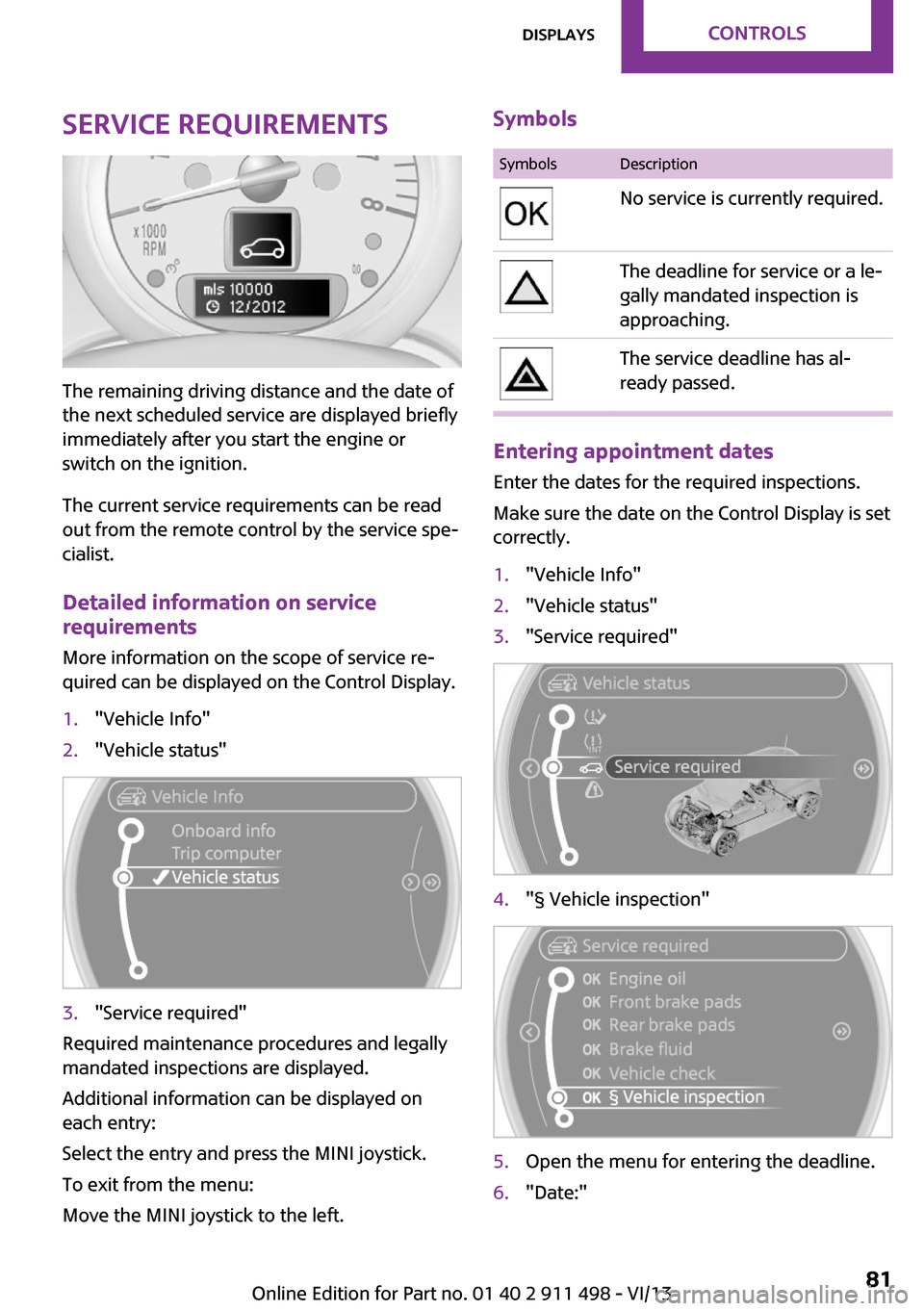
The remaining driving distance and the date of
the next scheduled service are displayed briefly
immediately after you start the engine or
switch on the ignition.
The current service requirements can be read
out from the remote control by the service spe‐
cialist.
Detailed information on service
requirements
More information on the scope of service re‐
quired can be displayed on the Control Display.
1."Vehicle Info"2."Vehicle status"3."Service required"
Required maintenance procedures and legally
mandated inspections are displayed.
Additional information can be displayed on
each entry:
Select the entry and press the MINI joystick.
To exit from the menu:
Move the MINI joystick to the left.
SymbolsSymbolsDescriptionNo service is currently required.The deadline for service or a le‐
gally mandated inspection is
approaching.The service deadline has al‐
ready passed.
Entering appointment dates
Enter the dates for the required inspections.
Make sure the date on the Control Display is set
correctly.
1."Vehicle Info"2."Vehicle status"3."Service required"4."§ Vehicle inspection"5.Open the menu for entering the deadline.6."Date:"Seite 81DisplaysControls81
Online Edition for Part no. 01 40 2 911 498 - VI/13
Page 82 of 288

7.Create the settings.8.Press the MINI joystick to apply the setting.
The year is highlighted.9.Turn the MINI joystick to create the setting.10.Press the MINI joystick to apply the setting.
The date entry is stored.
To exit from the menu:
Move the MINI joystick to the left.
Check Control The concept
The Check Control monitors vehicle functions
and alerts you to any malfunctions in the sys‐
tems being monitored.
A Check Control message consists of indicator
and warning lamps in the instrument cluster
and, in some circumstances, an acoustic signal
and text messages at the top of the Control Dis‐
play.
Indicator/warning lamps
The indicator and warning lamps can light up in
a variety of combinations and colors in display
area 1 or 2.
Several of the lamps are checked for proper
functioning and light up temporarily when the
engine is started or the ignition is switched on.
The symbol indicates that Check Control
messages have been stored. The Check Control
messages can be displayed later.
Text messages
Text messages at the upper edge of the Control
Display in combination with a symbol in the in‐
strument cluster explain a Check Control mes‐
sage and the meaning of the indicator and warning lamps.
Supplementary text messages Additional information, such as on the cause of
a fault or the required action, can be called up
via Check Control.
In urgent cases, this information will be shown
as soon as the corresponding lamp comes on.
Seite 82ControlsDisplays82
Online Edition for Part no. 01 40 2 911 498 - VI/13
Page 83 of 288

Hiding Check Control messages
Press the button on the turn indicator lever.
Some Check Control messages are displayed
continuously and are not cleared until the mal‐
function is eliminated. If several malfunctions
occur at once, the messages are displayed con‐
secutively.
They are marked with the symbol
shown here.
Other Check Control messages are hidden au‐
tomatically after approx. 20 seconds. However,
they are stored and can be displayed again
later.
They are marked with the symbol
shown here.
Viewing stored Check Control messages
The stored Check Control messages can only be
displayed while the driver's door is closed.1.Press the button on the turn indicator lever
repeatedly until "SET/INFO" is displayed.2.Press and hold the button until the display
changes.3.Press the button repeatedly until the corre‐
sponding symbol and "CHECK INFO" ap‐
pear on the display.4.Press and hold the button.
If there is no Check Control message, this is
indicated by "CHECK OK“.
If a Check Control message has been
stored, the corresponding message is dis‐
played.
The text message is also displayed on the
Control Display.5.Press the button to check for other mes‐
sages.Seite 83DisplaysControls83
Online Edition for Part no. 01 40 2 911 498 - VI/13
Page 84 of 288

Displaying on the Control Display1."Vehicle Info"2."Vehicle status"3."Check Control"4.Select the text message.Seite 84ControlsDisplays84
Online Edition for Part no. 01 40 2 911 498 - VI/13
Page 87 of 288
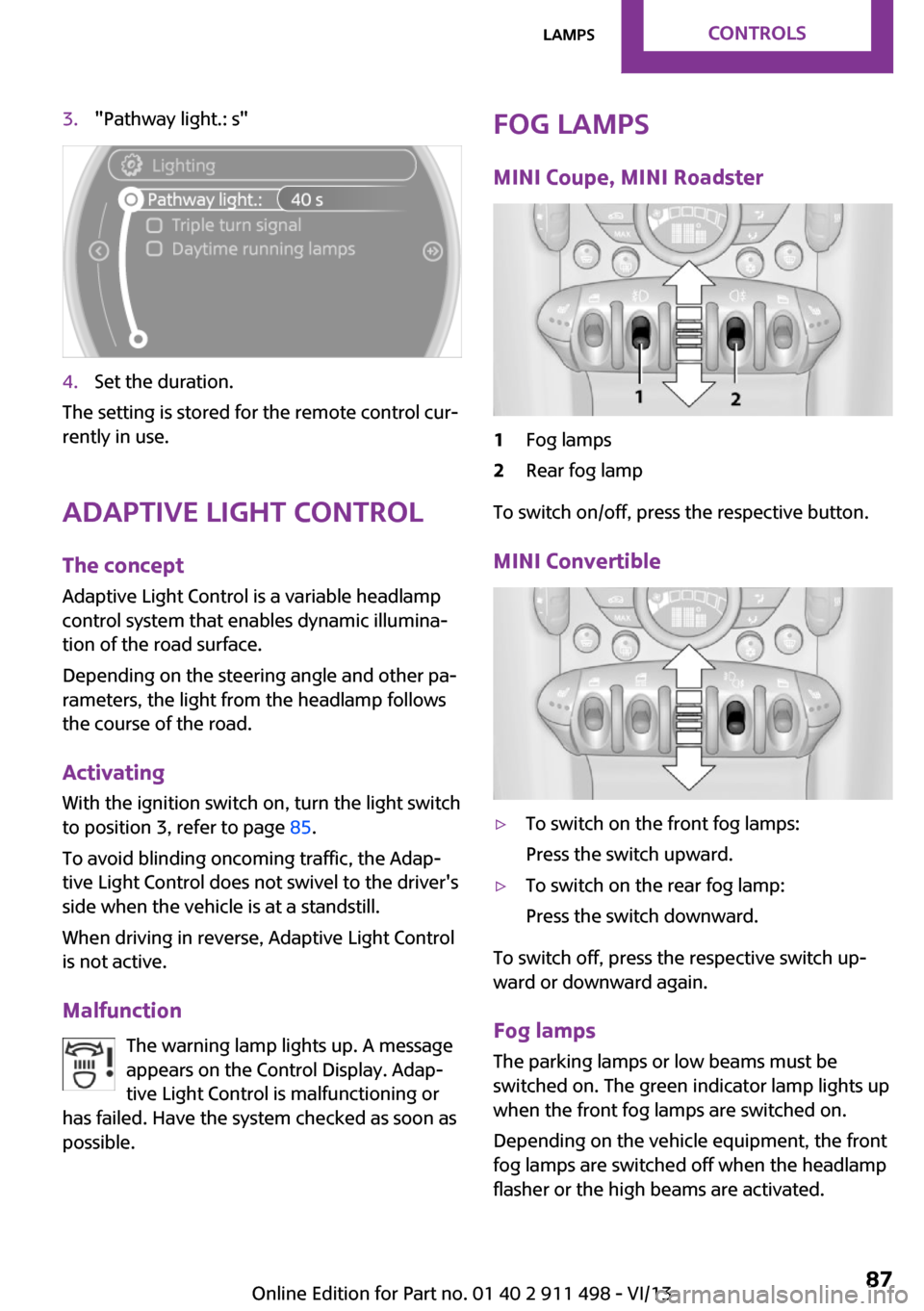
3."Pathway light.: s"4.Set the duration.
The setting is stored for the remote control cur‐
rently in use.
Adaptive Light Control
The concept
Adaptive Light Control is a variable headlamp
control system that enables dynamic illumina‐
tion of the road surface.
Depending on the steering angle and other pa‐
rameters, the light from the headlamp follows
the course of the road.
Activating
With the ignition switch on, turn the light switch
to position 3, refer to page 85.
To avoid blinding oncoming traffic, the Adap‐
tive Light Control does not swivel to the driver's
side when the vehicle is at a standstill.
When driving in reverse, Adaptive Light Control
is not active.
Malfunction The warning lamp lights up. A message
appears on the Control Display. Adap‐
tive Light Control is malfunctioning or
has failed. Have the system checked as soon as
possible.
Fog lamps
MINI Coupe, MINI Roadster1Fog lamps2Rear fog lamp
To switch on/off, press the respective button.
MINI Convertible
▷To switch on the front fog lamps:
Press the switch upward.▷To switch on the rear fog lamp:
Press the switch downward.
To switch off, press the respective switch up‐
ward or downward again.
Fog lamps
The parking lamps or low beams must be
switched on. The green indicator lamp lights up
when the front fog lamps are switched on.
Depending on the vehicle equipment, the front
fog lamps are switched off when the headlamp
flasher or the high beams are activated.
Seite 87LampsControls87
Online Edition for Part no. 01 40 2 911 498 - VI/13
Page 93 of 288

Do not obstruct the area of movement
Always keep the area of movement of the
rollover protection system clear. In light acci‐
dents, you are protected by the fastened safety
belt and, depending on the severity of the acci‐
dent, the belt tightener and the multi-level air
bag restraint system. ◀
Lowering
Have the service center check the rollover pro‐
tection system after it is deployed unexpect‐
edly.
General instructions on the rollover pro‐
tection system
When the rollover protection system is ex‐
tended, do not move the convertible top under
any circumstances.
Do not modify the individual components of
the rollover protection system or the wiring in
any way.
Work on the rollover protection system should only be performed by a MINI service center.
Non-professional work on the system could
lead to failure or a malfunction.
To check the system and to ensure that the sys‐
tem will operate properly over the long-term, it
is imperative that you adhere to the specified
service intervals. ◀
FTM Flat Tire Monitor
The concept
The system does not measure the actual infla‐
tion pressure in the tires.
The system detects a pressure loss in a tire by
comparing the rotational speeds of the individ‐
ual wheels while moving.
In the event of a pressure loss, the diameter
and therefore the rotational speed of the corre‐
sponding wheel change. This is detected and
reported as a flat tire.Functional requirements
The system must have been initialized when
the tire inflation pressure was correct; other‐
wise, reliable signaling of a flat tire is not en‐
sured.
Initialize the system after each correction of the
tire inflation pressure and after every tire or
wheel change.
System limits Sudden tire damage
Sudden serious tire damage caused by
external influences cannot be indicated in ad‐
vance. ◀
A natural, even pressure loss in all four tires
cannot be detected. Therefore, check the tire
inflation pressure regularly.
The system could be delayed or malfunction in
the following situations:▷When the system has not been initialized.▷When driving on a snowy or slippery road
surface.▷Sporty driving style: slip in the drive wheels,
high lateral acceleration.▷When driving with snow chains.
When the vehicle is driven with a compact
wheel, refer to page 250, the Flat Tire Monitor
is not functional.
Status display
The current status of the Flat Tire Monitor can
be displayed on the Control Display, e.g., whether or not the FTM is active.
1."Vehicle Info"2."Vehicle status"Seite 93SafetyControls93
Online Edition for Part no. 01 40 2 911 498 - VI/13
Page 94 of 288
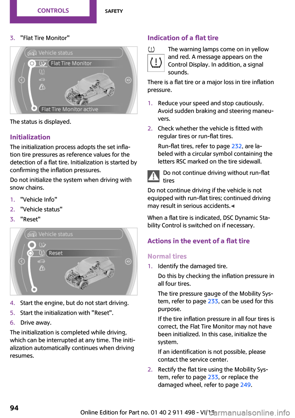
3."Flat Tire Monitor"
The status is displayed.
Initialization The initialization process adopts the set infla‐
tion tire pressures as reference values for the
detection of a flat tire. Initialization is started by
confirming the inflation pressures.
Do not initialize the system when driving with
snow chains.
1."Vehicle Info"2."Vehicle status"3."Reset"4.Start the engine, but do not start driving.5.Start the initialization with "Reset".6.Drive away.
The initialization is completed while driving,
which can be interrupted at any time. The initi‐
alization automatically continues when driving
resumes.
Indication of a flat tire
The warning lamps come on in yellow
and red. A message appears on the
Control Display. In addition, a signal
sounds.
There is a flat tire or a major loss in tire inflation
pressure.1.Reduce your speed and stop cautiously.
Avoid sudden braking and steering maneu‐
vers.2.Check whether the vehicle is fitted with
regular tires or run-flat tires.
Run-flat tires, refer to page 232, are la‐
beled with a circular symbol containing the
letters RSC marked on the tire sidewall.
Do not continue driving without run-flat
tires
Do not continue driving if the vehicle is not
equipped with run-flat tires; continued driving
may result in serious accidents. ◀
When a flat tire is indicated, DSC Dynamic Sta‐
bility Control is switched on if necessary.
Actions in the event of a flat tire
Normal tires
1.Identify the damaged tire.
Do this by checking the inflation pressure in
all four tires.
The tire pressure gauge of the Mobility Sys‐
tem, refer to page 233, can be used for this
purpose.
If the tire inflation pressure in all four tires is
correct, the Flat Tire Monitor may not have
been initialized. In this case, initialize the
system.
If an identification is not possible, please
contact the service center.2.Rectify the flat tire using the Mobility Sys‐
tem, refer to page 233, or replace the
damaged wheel, refer to page 249.Seite 94ControlsSafety94
Online Edition for Part no. 01 40 2 911 498 - VI/13
Page 96 of 288
The system is inactive and cannot indicate a flat
tire:▷If a wheel without TPM electronics is
mounted, e.g., compact wheel.▷For a mounted wheel without TPM elec‐
tronics.▷When the TPM is disturbed by other sys‐
tems or devices with the same radio fre‐
quency.
Status display
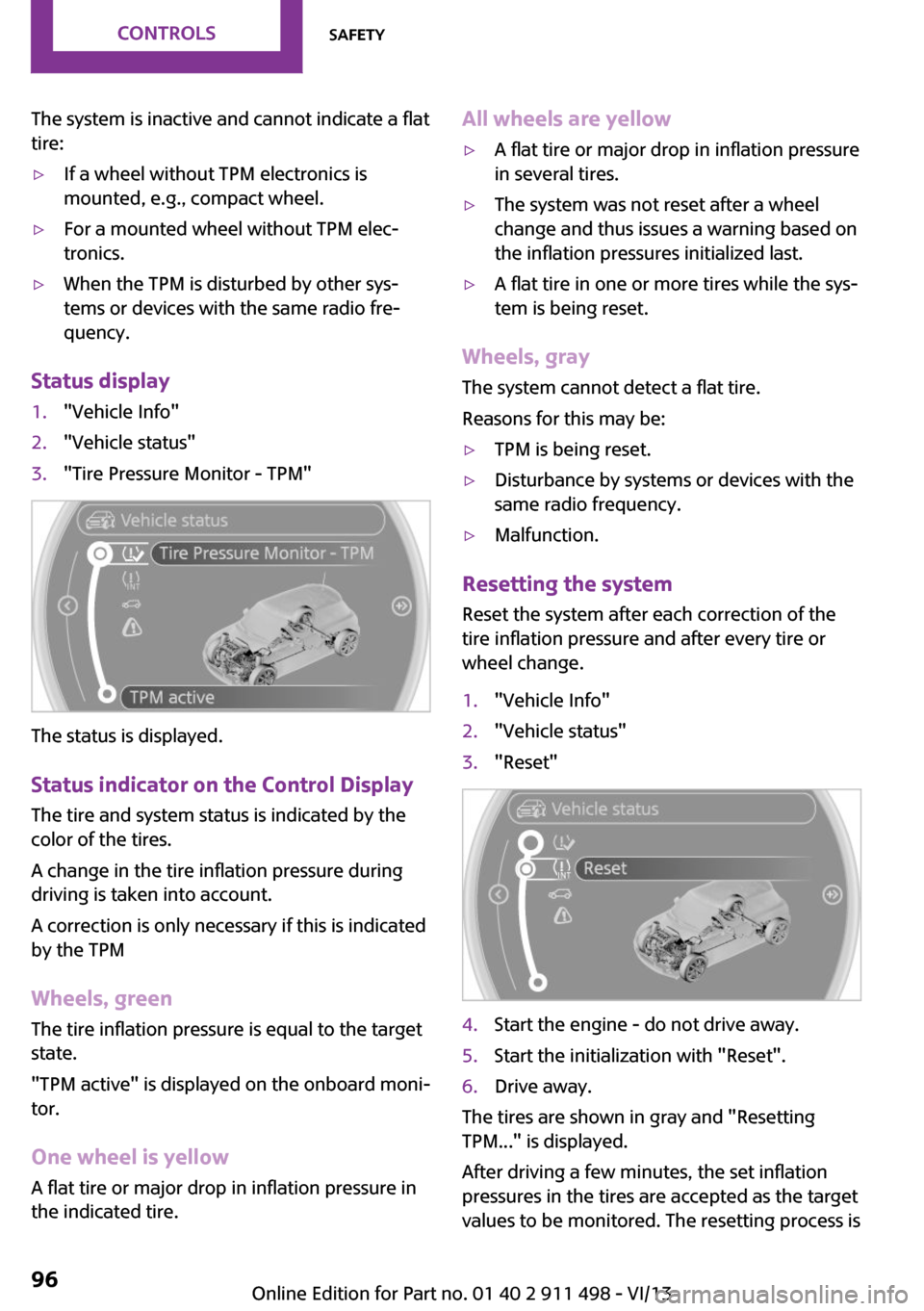
1."Vehicle Info"2."Vehicle status"3."Tire Pressure Monitor - TPM"
The status is displayed.
Status indicator on the Control Display The tire and system status is indicated by the
color of the tires.
A change in the tire inflation pressure during
driving is taken into account.
A correction is only necessary if this is indicated
by the TPM
Wheels, green
The tire inflation pressure is equal to the target
state.
"TPM active" is displayed on the onboard moni‐
tor.
One wheel is yellow A flat tire or major drop in inflation pressure in
the indicated tire.
All wheels are yellow▷A flat tire or major drop in inflation pressure
in several tires.▷The system was not reset after a wheel
change and thus issues a warning based on
the inflation pressures initialized last.▷A flat tire in one or more tires while the sys‐
tem is being reset.
Wheels, gray
The system cannot detect a flat tire.
Reasons for this may be:
▷TPM is being reset.▷Disturbance by systems or devices with the
same radio frequency.▷Malfunction.
Resetting the system
Reset the system after each correction of the
tire inflation pressure and after every tire or
wheel change.
1."Vehicle Info"2."Vehicle status"3."Reset"4.Start the engine - do not drive away.5.Start the initialization with "Reset".6.Drive away.
The tires are shown in gray and "Resetting
TPM..." is displayed.
After driving a few minutes, the set inflation
pressures in the tires are accepted as the target
values to be monitored. The resetting process is
Seite 96ControlsSafety96
Online Edition for Part no. 01 40 2 911 498 - VI/13
Page 97 of 288
completed automatically as you drive. On the
Control Display, the tires are shown in green
and "Status: TPM active" is displayed again.
The trip can be interrupted at any time. If you
drive away again, the process resumes auto‐
matically.
If a flat tire is detected while the system is re‐
setting, all tires on the Control Display are dis‐
played in yellow. The message "Low tire!" is
shown.
Low tire pressure message The warning lamps come on in yellow
and red. A message is displayed on the
onboard monitor. In addition, a signal
sounds.▷There is a flat tire or substantial loss of infla‐
tion pressure on the indicated wheel.▷The system was not reset after a wheel
change and thus issues warnings based on
the inflation pressures initialized last.1.Reduce your speed and stop cautiously.
Avoid sudden braking and steering maneu‐
vers.2.Check whether the vehicle is fitted with
regular tires or run-flat tires.
Run-flat tires, refer to page 232, are la‐
beled with a circular symbol containing the
letters RSC marked on the tire sidewall.
Do not continue driving without run-flat
tires
Do not continue driving if the vehicle is not
equipped with run-flat tires; continued driving
may result in serious accidents. ◀
When a low inflation pressure is indicated, DSC
Dynamic Stability Control is switched on if nec‐
essary.
Actions in the event of a flat tire Normal tires
1.Identify the damaged tire.Do this by checking the air pressure in all
four tires. The tire pressure gauge of the
Mobility System, refer to page 233, can be
used for this purpose.
If the tire inflation pressure in all four tires is
correct, the Tire Pressure Monitor may not
have been reset. Reset the system.
If an identification is not possible, please
contact the service center.2.Rectify the flat tire using the Mobility Sys‐
tem, refer to page 233, or replace the
damaged wheel, refer to page 249.
Use of tire sealant, e.g., the Mobility Sys‐
tem, may damage the TPM wheel electron‐
ics. In this case, have the electronics
checked at the next opportunity and have
them replaced if necessary.
Run-flat tires
You can continue driving with a damaged tire
at speeds up to 50 mph/80 km/h.
Do not continue driving without run-flat
tires
Do not continue driving if the vehicle is not
equipped with run-flat tires; continued driving
may result in serious accidents. ◀
Continued driving with a flat tire
If continuing to drive with a damaged tire:
1.Avoid sudden braking and steering maneu‐
vers.2.Do not exceed a speed of 50 mph/80 km/h.3.Check the air pressure in all four tires at the
next opportunity.
If the tire inflation pressure in all four tires is
correct, the Tire Pressure Monitor may not
have been reset. Reset the system.
Possible driving distance with complete loss of
tire inflation pressure:
The possible driving distance after a loss of tire
inflation pressure depends on the cargo load
and the driving style and conditions.
Seite 97SafetyControls97
Online Edition for Part no. 01 40 2 911 498 - VI/13