warning light MINI Coupe 2014 Owner's Manual (Mini Connected)
[x] Cancel search | Manufacturer: MINI, Model Year: 2014, Model line: Coupe, Model: MINI Coupe 2014Pages: 288, PDF Size: 6.72 MB
Page 16 of 288

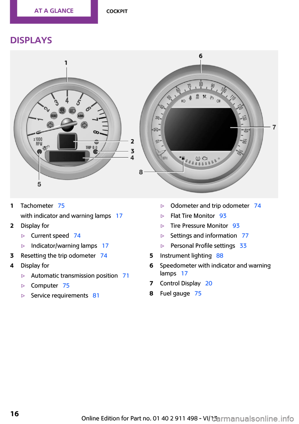
Displays1Tachometer 75
with indicator and warning lamps 172Display for▷Current speed 74▷Indicator/warning lamps 173Resetting the trip odometer 744Display for▷Automatic transmission position 71▷Computer 75▷Service requirements 81▷Odometer and trip odometer 74▷Flat Tire Monitor 93▷Tire Pressure Monitor 93▷Settings and information 77▷Personal Profile settings 335Instrument lighting 886Speedometer with indicator and warning
lamps 177Control Display 208Fuel gauge 75Seite 16At a glanceCockpit16
Online Edition for Part no. 01 40 2 911 498 - VI/13
Page 17 of 288

Indicator/warning lamps
The concept
The indicator and warning lamps can light up in
a variety of combinations and colors in display
area 1 or 2.
Several of the lamps are checked for proper
functioning when the engine is started or the
ignition is switched on, and light up briefly.
Text messages
Text messages at the upper edge of the Control
Display explain the meaning of the displayed
indicator and warning lamps.
Supplementary text messages
You can call up more information, e.g., on the
cause of a malfunction and on how to respond,
via Check Control, refer to page 82.
In urgent cases, this information will be shown
as soon as the corresponding lamp comes on.
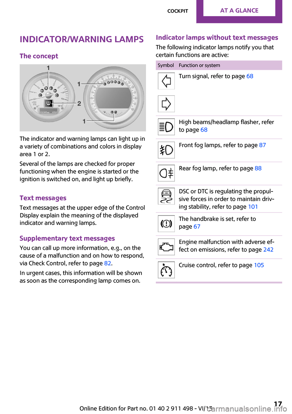
Indicator lamps without text messages
The following indicator lamps notify you that
certain functions are active:SymbolFunction or systemTurn signal, refer to page 68High beams/headlamp flasher, refer
to page 68Front fog lamps, refer to page 87Rear fog lamp, refer to page 88DSC or DTC is regulating the propul‐
sive forces in order to maintain driv‐
ing stability, refer to page 101The handbrake is set, refer to
page 67Engine malfunction with adverse ef‐
fect on emissions, refer to page 242Cruise control, refer to page 105Seite 17CockpitAt a glance17
Online Edition for Part no. 01 40 2 911 498 - VI/13
Page 19 of 288

All around the head‐
liner1Indicator/warning lamps for the front pas‐
senger airbags 922Switch panelReading lamps 88MINI Roadster: interior lamps/
reading lamps 88Ambient lighting color 89MINI Coupe, MINI Roadster: ex‐
tending and retracting the spoiler
manually 103MINI Convertible: opening and
closing the sliding sunroof or
convertible top 43
MINI Roadster: opening and clos‐
ing the convertible top 51Interior lamps 88All around the shift/
selector lever1USB audio interface 1722Buttons in the center consoleSport button 103Driving stability control sys‐
tems 1013MINI joystick with buttons 20Seite 19CockpitAt a glance19
Online Edition for Part no. 01 40 2 911 498 - VI/13
Page 34 of 288

impossible to unlock the doors using the
lock buttons or door handles.▷The welcome lamps, interior lamps, and
ambient lighting are switched on and off.▷The alarm system is armed or disarmed, re‐
fer to page 41.
Operating from the inside
Via the button for the central locking system,
refer to page 37.
In an accident of the necessary severity, the
central locking system unlocks automatically.
The hazard warning system and interior lamps
come on.
Opening and closing:
from the outside
Using the remote control
General information Take the remote control with you
People or animals left unattended in a
parked vehicle can lock the doors from the in‐
side. Always take the remote control with you
when leaving the vehicle so that the vehicle
can then be opened from the outside. ◀
Unlocking
Press the button. The vehicle is un‐
locked.
The welcome lamps and interior lamps are
switched on.
You can set how the vehicle is to be unlocked.
The setting is stored for the remote control cur‐
rently in use.1."Settings"2."Door locks"3."Unlock button"4.Select the desired function:▷"All doors"
Press the button once: the en‐
tire vehicle unlocks.
▷"Driver's door only"
Pressing the button once un‐
locks only the driver's door and the fuel
filler flap. Pressing twice unlocks the
entire vehicle.
Convenient opening
Press and hold the button on the re‐
mote control.
The power windows are opened. In the
MINI Convertible, the sliding sunroof is opened
as well.
Seite 34ControlsOpening and closing34
Online Edition for Part no. 01 40 2 911 498 - VI/13
Page 40 of 288

▷The engine can only be started if the re‐
mote control is inside the vehicle.▷The doors and tailgate must be closed to
operate the windows.
Comparison with ordinary remote
control
The functions can be controlled by pressing the
buttons or via Comfort Access.
Notes on opening and closing, refer to page 32.
If you notice a brief delay while opening or
closing the windows or convertible top, the sys‐
tem is checking whether a remote control is in‐
side the vehicle. Repeat the opening or closing
procedure, if necessary.
Unlocking
Press button 1.
Depending on the setting, either only the driv‐
er's door or the entire vehicle is unlocked, refer
to page 34.
Pressing the button again locks the entire vehi‐
cle again.
Convenient opening with the remote control,
refer to page 34.
Locking
Press button 1.
MINI Convertible, MINI Roadster:
windows and convertible top operation
In the radio ready state and beyond, the win‐
dows and the electrical convertible top can be
opened and closed when a remote control is lo‐
cated inside the vehicle.
Unlocking the tailgate separately Press the button on the exterior of the tailgate.
This corresponds to pressing the following but‐
ton on the remote control:
.
If a remote control accidentally left in the cargo
area is detected in the locked vehicle after the
tailgate is closed, the tailgate opens again
slightly. The hazard warning system flashes and
an acoustic signal sounds.
Power windows When the engine is switched off, the windows
can be operated as long as neither the doors
nor the tailgate are opened.
When the door and tailgate are closed again
and the remote control is detected inside the
vehicle, the windows can be operated again.
Insert the remote control into the ignition lock
to be able to operate the windows while the
engine is switched off and the doors are open.
Switching on the radio ready state Press the Start/Stop button to switch on the
radio ready state, refer to page 65.
Do not depress the brake or the clutch; other‐
wise, the engine will start.
Starting the engine The engine can be started or the ignition can
be switched on, refer to page 65, when a re‐
mote control is inside the vehicle. It is not nec‐
essary to insert a remote control into the igni‐
tion lock.
Switching off the engine in cars with
automatic transmission
The engine can only be switched off with the
selector lever in position P, refer to page 71.
Seite 40ControlsOpening and closing40
Online Edition for Part no. 01 40 2 911 498 - VI/13
Page 41 of 288

To switch off the engine with the selector lever
in position N, the remote control must be in‐
serted in the ignition lock.
Before driving a vehicle with automatic
transmission into a car wash1.Insert the remote control into the ignition
switch.2.Depress the brake pedal.3.Move the selector lever to position N.4.Switch the engine off.
The vehicle can roll.
Malfunction The Comfort Access functions can be disturbed
by local radio waves, such as by a mobile
phone in the immediate vicinity of the remote
control or when a mobile phone is being
charged in the vehicle.
If this occurs, open or close the vehicle using
the buttons on the remote control or use the
integrated key in the door lock.
To start the engine afterward, insert the remote
control into the ignition switch.
Warning lamps The warning lamp in the instrument
cluster lights up when you attempt to
start the engine: the engine cannot be
started.
The remote control is not in the vehicle or has a
malfunction. Take the remote control with you
inside the vehicle or have it checked. If neces‐
sary, insert another remote control into the ig‐
nition switch.
The warning lamp in the instrument
cluster lights up while the engine is run‐
ning: the remote control is no longer in‐
side the vehicle.
After switching off the engine, the engine can
only be started again within approx. 10 sec‐
onds if no door has been opened.
The indicator lamp lights up and a mes‐
sage appears on the Control Display: re‐
place the remote control battery.
Replacing the battery
The remote control for Comfort Access contains
a battery that will need to be replaced from
time to time.1.Remove the cover.2.Insert a new battery with the positive side
facing upwards.3.Press the cover closed.
Return used battery to a recycling center
or to your service center.
Alarm system
The concept
The enabled alarm system reacts to the follow‐
ing:
▷Opening of a door, the hood or the tailgate.▷Movements inside the vehicle.▷Changes in the vehicle tilt, e.g., during at‐
tempts to steal a wheel or tow the car.▷Interruptions in battery voltage.
Depending on the market-specific version, the
alarm system briefly signals unauthorized entry
attempts by:
▷By sounding an acoustic alarm.▷By switching on the hazard warning system.Seite 41Opening and closingControls41
Online Edition for Part no. 01 40 2 911 498 - VI/13
Page 65 of 288

DrivingVehicle equipmentThis chapter describes all series equipment as
well as country-specific and special equipment
offered for this model series.Therefore, it also
describes equipment that may not be found in
your vehicle, for instance due to the selected
special equipment or the country version. This
also applies to safety-related functions and sys‐
tems.
Ignition lock Insert the remote control into the
ignition lock
Insert the remote control all the way into the
ignition lock.
Radio ready state is switched on. Individual
electrical consumers can operate.
Removing the remote control from the
ignition lock
Do not forcibly pull the remote control
out of the ignition lock
Do not forcibly pull the remote control out of
the ignition lock as this may cause damage. ◀
Before removing the remote control, push it all
the way in to release the locking mechanism.
The ignition is switched off if it was on.
Automatic transmission
You can only take out the remote control if
transmission position P is engaged: interlock.
Start/Stop button
Pressing the Start/Stop button switches the ig‐
nition on or off and starts the engine.
The engine starts when the Start/Stop button is
pressed and:
▷Manual transmission: the clutch is de‐
pressed.▷Automatic transmission: the brake is de‐
pressed.
Radio ready state
Individual electrical consumers can operate.
Radio ready state is switched off automatically:
▷When the remote control is removed from
the ignition lock.▷With Comfort Access, refer to page 39, by
pressing the button on the door handle or
the
button on the remote control.
▷After a certain period of time.
Ignition on All electrical consumers can operate. Most indi‐
cator and warning lamps light up for different
lengths of time.
Seite 65DrivingControls65
Online Edition for Part no. 01 40 2 911 498 - VI/13
Page 74 of 288

DisplaysVehicle equipment
This chapter describes all series equipment as
well as country-specific and special equipment
offered for this model series.Therefore, it also
describes equipment that may not be found in
your vehicle, for instance due to the selected
special equipment or the country version. This
also applies to safety-related functions and sys‐
tems.
Odometer, external tem‐
perature display, clock
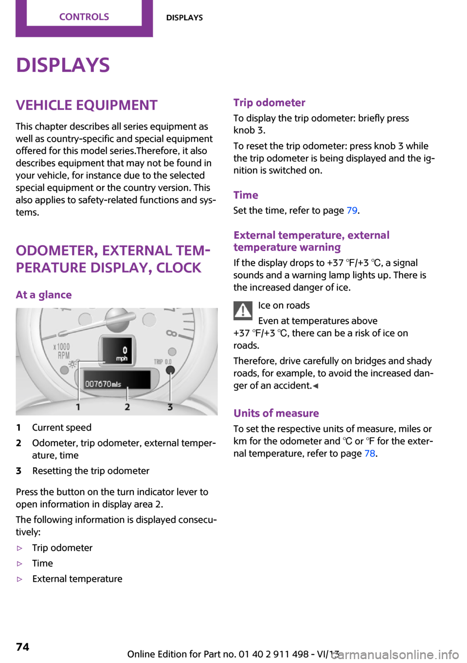
At a glance1Current speed2Odometer, trip odometer, external temper‐
ature, time3Resetting the trip odometer
Press the button on the turn indicator lever to
open information in display area 2.
The following information is displayed consecu‐
tively:
▷Trip odometer▷Time▷External temperatureTrip odometer
To display the trip odometer: briefly press
knob 3.
To reset the trip odometer: press knob 3 while
the trip odometer is being displayed and the ig‐
nition is switched on.
Time Set the time, refer to page 79.
External temperature, external temperature warning
If the display drops to +37 ℉/+3 ℃, a signal
sounds and a warning lamp lights up. There is
the increased danger of ice.
Ice on roads
Even at temperatures above
+37 ℉/+3 ℃, there can be a risk of ice on
roads.
Therefore, drive carefully on bridges and shady
roads, for example, to avoid the increased dan‐
ger of an accident. ◀
Units of measure
To set the respective units of measure, miles or
km for the odometer and ℃ or ℉ for the exter‐
nal temperature, refer to page 78.Seite 74ControlsDisplays74
Online Edition for Part no. 01 40 2 911 498 - VI/13
Page 82 of 288

7.Create the settings.8.Press the MINI joystick to apply the setting.
The year is highlighted.9.Turn the MINI joystick to create the setting.10.Press the MINI joystick to apply the setting.
The date entry is stored.
To exit from the menu:
Move the MINI joystick to the left.
Check Control The concept
The Check Control monitors vehicle functions
and alerts you to any malfunctions in the sys‐
tems being monitored.
A Check Control message consists of indicator
and warning lamps in the instrument cluster
and, in some circumstances, an acoustic signal
and text messages at the top of the Control Dis‐
play.
Indicator/warning lamps
The indicator and warning lamps can light up in
a variety of combinations and colors in display
area 1 or 2.
Several of the lamps are checked for proper
functioning and light up temporarily when the
engine is started or the ignition is switched on.
The symbol indicates that Check Control
messages have been stored. The Check Control
messages can be displayed later.
Text messages
Text messages at the upper edge of the Control
Display in combination with a symbol in the in‐
strument cluster explain a Check Control mes‐
sage and the meaning of the indicator and warning lamps.
Supplementary text messages Additional information, such as on the cause of
a fault or the required action, can be called up
via Check Control.
In urgent cases, this information will be shown
as soon as the corresponding lamp comes on.
Seite 82ControlsDisplays82
Online Edition for Part no. 01 40 2 911 498 - VI/13
Page 87 of 288

3."Pathway light.: s"4.Set the duration.
The setting is stored for the remote control cur‐
rently in use.
Adaptive Light Control
The concept
Adaptive Light Control is a variable headlamp
control system that enables dynamic illumina‐
tion of the road surface.
Depending on the steering angle and other pa‐
rameters, the light from the headlamp follows
the course of the road.
Activating
With the ignition switch on, turn the light switch
to position 3, refer to page 85.
To avoid blinding oncoming traffic, the Adap‐
tive Light Control does not swivel to the driver's
side when the vehicle is at a standstill.
When driving in reverse, Adaptive Light Control
is not active.
Malfunction The warning lamp lights up. A message
appears on the Control Display. Adap‐
tive Light Control is malfunctioning or
has failed. Have the system checked as soon as
possible.
Fog lamps
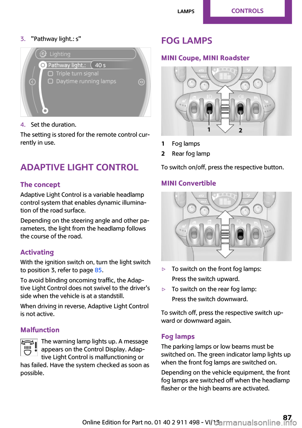
MINI Coupe, MINI Roadster1Fog lamps2Rear fog lamp
To switch on/off, press the respective button.
MINI Convertible
▷To switch on the front fog lamps:
Press the switch upward.▷To switch on the rear fog lamp:
Press the switch downward.
To switch off, press the respective switch up‐
ward or downward again.
Fog lamps
The parking lamps or low beams must be
switched on. The green indicator lamp lights up
when the front fog lamps are switched on.
Depending on the vehicle equipment, the front
fog lamps are switched off when the headlamp
flasher or the high beams are activated.
Seite 87LampsControls87
Online Edition for Part no. 01 40 2 911 498 - VI/13