check engine MINI COUPE ROADSTER CONVERTIBLE 2012 User Guide
[x] Cancel search | Manufacturer: MINI, Model Year: 2012, Model line: COUPE ROADSTER CONVERTIBLE, Model: MINI COUPE ROADSTER CONVERTIBLE 2012Pages: 283, PDF Size: 9.38 MB
Page 121 of 283

DRIVING TIPSThings to remember when driving
120
Always position and secure the cargo as
described above, so that it cannot endan-
ger the car's occupants, for example if sudden
braking or swerves are necessary.
Do not exceed the approved gross vehicle
weight and axle loads, page 257 257; other-
wise, the operating safety of the vehicle is no
longer assured and the vehicle will not be in
compliance with the construction and use
regulations.
Heavy or hard objects should not be carried
loose inside the car, since they could be thrown
around, for example as a result of heavy braking,
sudden swerves, etc., and endanger the occu-
pants. Do not secure cargo using the fastening
points for the tether strap, page 58; they may
become damaged. <
Rear luggage rack
A special rack system is available as an option
for your MINI. Please note the information
contained in the asse mbly instructions.
Mounting points
The mounting points are under the protective
caps in the bumper.
Push out the caps at the respective slots.
Loading rear luggage rack
When loading, make su re that the maximum
allowed roof load, the gross vehicle weight and
the axle loads are not exceeded.
You can find the applicable data under Weights
on page 257.
Saving fuel
Your vehicle incorporates numerous technolo-
gies for reducing fuel consumption and
emissions.
Fuel consumption depends on a number of dif-
ferent factors. Fuel consumption and environ-
mental pollution are affect ed by various actions,
the manner of driving and regular maintenance.
Remove unnecessary cargo
Additional weight increases fuel consumption.
Remove attached parts no longer in use
Remove luggage rack if no longer needed after
use.
Attached parts on the ve hicle affect its aerody-
namics and increase fuel consumption.
Closing windows
Open windows increase air resistance and
therefore fuel consumption.
Check tire inflation pressure regularly
Check and, if necessary, correct tire inflation
pressure at least twic e a month and before
starting on a long trip.
Low inflation pressure increases rolling resis-
tance and thus leads to greater fuel consump-
tion and tire wear.
Drive off immediately
Do not wait for the engine to warm up while the
vehicle remains stationary. Start driving right
away, but at moderate engi ne speeds. This is the
fastest way for the cold engine to reach its oper-
ating temperature.
Think ahead while driving
Avoid unnecessary accelera tion and braking. by
maintaining a suitable di stance to the vehicle
driving ahead.
Looking-ahead and smooth driving reduces fuel
consumption.
00320051004F004C00510048000300280047004C0057004C005200510003
Page 223 of 283
MOBILITYEngine compartment
222
Hood
Releasing
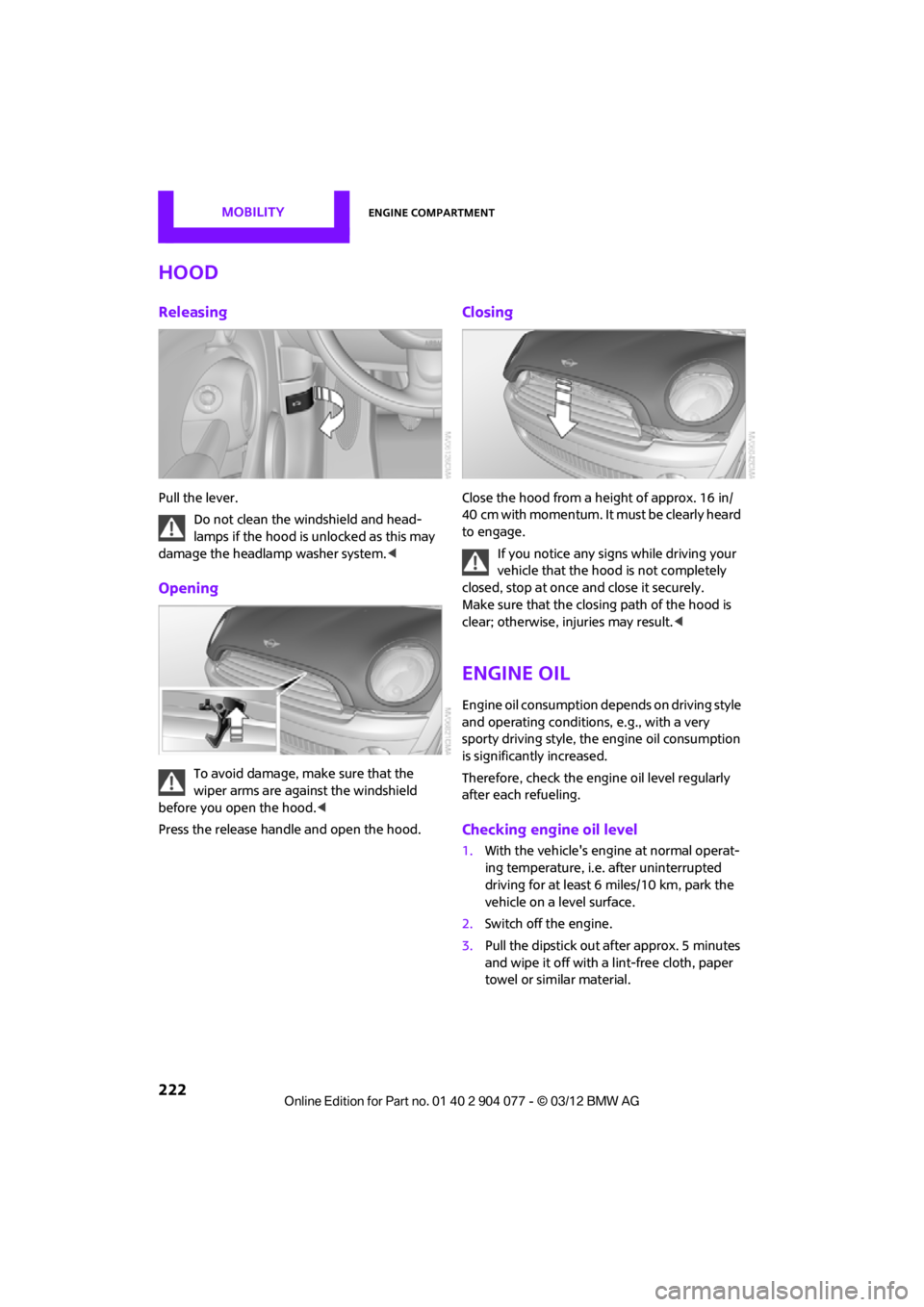
Pull the lever.Do not clean the windshield and head-
lamps if the hood is unlocked as this may
damage the headlamp washer system. <
Opening
To avoid damage, make sure that the
wiper arms are against the windshield
before you open the hood. <
Press the release handle and open the hood.
Closing
Close the hood from a height of approx. 16 in/
40 cm with momentum. It must be clearly heard
to engage.
If you notice any signs while driving your
vehicle that the hood is not completely
closed, stop at once and close it securely.
Make sure that the closing path of the hood is
clear; otherwise, injuries may result. <
Engine oil
Engine oil consumption depends on driving style
and operating conditions, e.g., with a very
sporty driving style, the engine oil consumption
is significantly increased.
Therefore, check the engine oil level regularly
after each refueling.
Checking engine oil level
1. With the vehicle's engine at normal operat-
ing temperature, i.e. after uninterrupted
driving for at least 6 miles/10 km, park the
vehicle on a level surface.
2. Switch off the engine.
3. Pull the dipstick out after approx. 5 minutes
and wipe it off with a lint-free cloth, paper
towel or similar material.
00320051004F004C00510048000300280047004C0057004C005200510003
Page 224 of 283
Engine compartmentMOBILITY
223
4.Carefully push the dipstick all the way into
the guide tube and pull it out again.
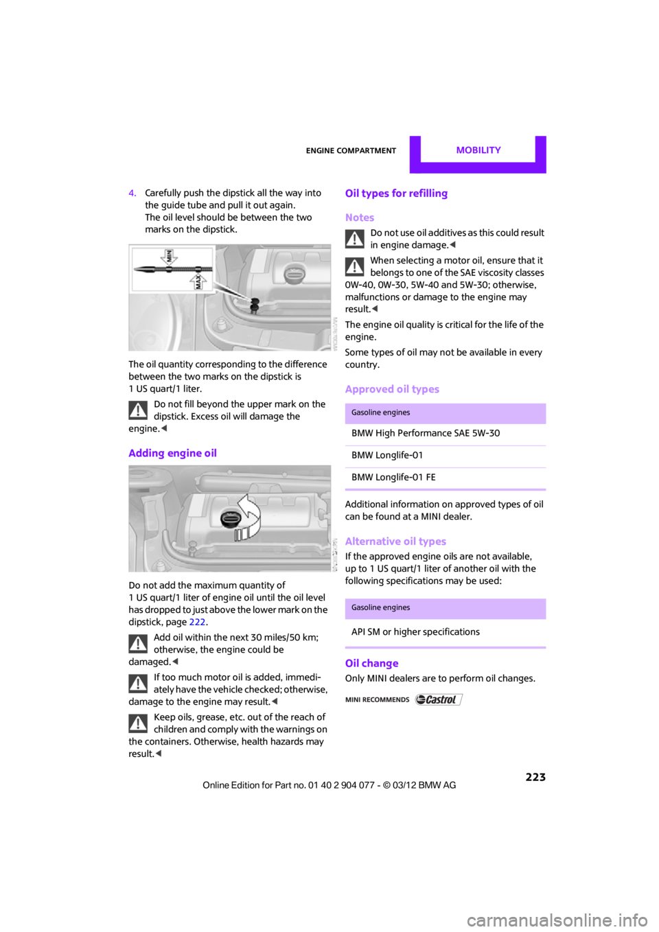
The oil level should be between the two
marks on the dipstick.
The oil quantity corresponding to the difference
between the two marks on the dipstick is
1 US quart/1 liter. Do not fill beyond the upper mark on the
dipstick. Excess oil will damage the
engine. <
Adding engine oil
Do not add the maximum quantity of
1 US quart/1 liter of engine oil until the oil level
has dropped to just abov e the lower mark on the
dipstick, page 222.
Add oil within the next 30 miles/50 km;
otherwise, the engine could be
damaged. <
If too much motor oi l is added, immedi-
ately have the vehicle checked; otherwise,
damage to the engine may result.<
Keep oils, grease, etc. out of the reach of
children and comply with the warnings on
the containers. Otherwise, health hazards may
result. <
Oil types for refilling
Notes
Do not use oil additives as this could result
in engine damage. <
When selecting a motor oil, ensure that it
belongs to one of the SAE viscosity classes
0W-40, 0W-30, 5W-40 and 5W-30; otherwise,
malfunctions or damage to the engine may
result. <
The engine oil quality is critical for the life of the
engine.
Some types of oil may not be available in every
country.
Approved oil types
Additional information on approved types of oil
can be found at a MINI dealer.
Alternative oil types
If the approved engine oils are not available,
up to 1 US quart/1 liter of another oil with the
following specifications may be used:
Oil change
Only MINI dealers are to perform oil changes.
Gasoline engines
BMW High Performance SAE 5W-30
BMW Longlife-01
BMW Longlife-01 FE
Gasoline engines
API SM or higher specifications
00320051004F004C00510048000300280047004C0057004C005200510003
Page 225 of 283
MOBILITYEngine compartment
224
Coolant
Coolant consists of half water and half additive.
Not all commercially available additives are suit-
able for your MINI. Your MINI dealer knows
which additives are suitab le and will be glad to
advise you.
Only use suitable additives; otherwise,
engine damage may result. Because addi-
tives are harmful to your health, it is important
to follow the instructions on the containers. <
Comply with the appropriate environmen-
tal protection regulations when disposing
of coolant additives. <
Coolant temperature
If the coolant, and therefore the engine, should
overheat, then a warning lamp will go on.
A message appears on the Control Display.
Checking coolant level
Do not add coolant to the cooling system
when the engine is hot. Escaping coolant
can cause burns. <
Do not open the hood until the engine has
cooled down.
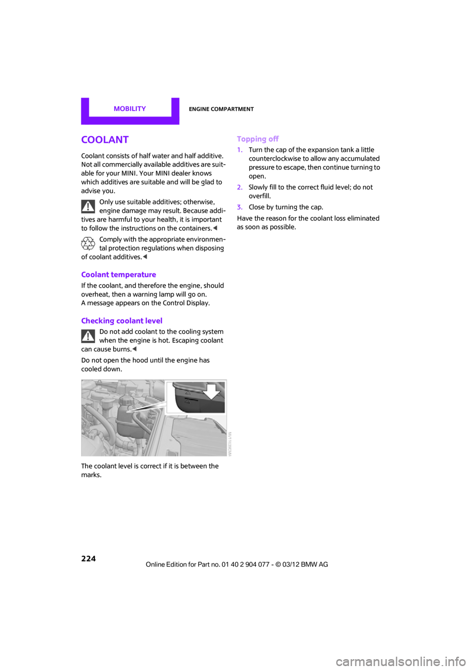
The coolant level is correct if it is between the
marks.
Topping off
1. Turn the cap of the expansion tank a little
counterclockwise to allow any accumulated
pressure to escape, then continue turning to
open.
2. Slowly fill to the correct fluid level; do not
overfill.
3. Close by turning the cap.
Have the reason for the coolant loss eliminated
as soon as possible.
00320051004F004C00510048000300280047004C0057004C005200510003
Page 227 of 283
MOBILITYMaintenance
226
Socket for On-Board
Diagnosis OBD
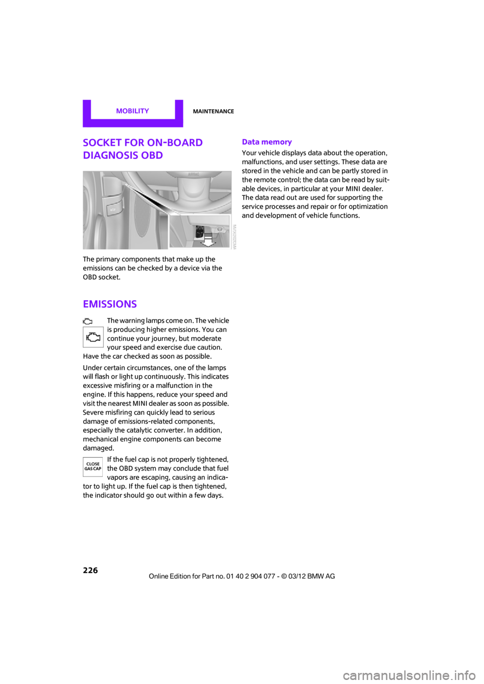
The primary components that make up the
emissions can be checked by a device via the
OBD socket.
Emissions
The warning lamps come on. The vehicle
is producing higher emissions. You can
continue your journey, but moderate
your speed and exercise due caution.
Have the car checked as soon as possible.
Under certain circumstances, one of the lamps
will flash or light up cont inuously. This indicates
excessive misfiring or a malfunction in the
engine. If this happens, reduce your speed and
visit the nearest MINI dealer as soon as possible.
Severe misfiring can quickly lead to serious
damage of emissions-related components,
especially the catalytic converter. In addition,
mechanical engine components can become
damaged.
If the fuel cap is not properly tightened,
the OBD system may conclude that fuel
vapors are escaping, causing an indica-
tor to light up. If the fuel cap is then tightened,
the indicator should go out within a few days.
Data memory
Your vehicle displays data about the operation,
malfunctions, and user settings. These data are
stored in the vehicle and can be partly stored in
the remote control; the data can be read by suit-
able devices, in particul ar at your MINI dealer.
The data read out are used for supporting the
service processes and repair or for optimization
and development of vehicle functions.
00320051004F004C00510048000300280047004C0057004C005200510003
Page 234 of 283
Replacing componentsMOBILITY
233
Light-emitting diodes LEDs
Light-emitting diodes installed behind translu-
cent lenses serve as the light sources for many of
the controls and displays in your vehicle. These
light-emitting diodes are related to conven-
tional laser diodes, and legislation defines them
as Class 1 light-emitting diodes.
Do not remove the covers or expose the
eyes directly to the unfiltered light source
for several hours; otherw ise, this could cause
irritation of the retina. <
Headlamp glass lens
In cool or humid weather, condensation may
occur on the interiors of the headlamps. The
condensation disappears a short time after the
light is switched on. The headlamps do not need
to be changed.
Do not remove the condensation from head-
lamps, despite driving with lights on, and if
condensation increases, e.g., because of water
droplets, have this checked by your MINI dealer.
Xenon lamps
The service life of these bulbs is very long and
the probability of failure very low, provided that
they are not switched on and off an excessive
number of times. If a xenon lamp fails neverthe-
less, switch on the fog lamps and continue the
journey with great care, provided that local leg-
islation does not prohibit this.
Work on the xenon lighting system,
including lamp replacem ent, is only to be
carried out only by your MINI dealer. Due to high
voltage, there is a risk of fatal injury if work on
the xenon lamps is carried out improperly. <
Halogen low beams and high beams
H13 bulb, 60/5 watts
The H13 bulb is pressurized. Therefore,
wear safety glasses an d protective gloves.
Otherwise, there is a risk of injury if the bulb is
damaged. < Be careful when inst
alling the cover;
otherwise, leaks could occur and cause
damage to the headlamp system. <
Accessing the lamp from the engine
compartment
The low-beam/high-beam bulb can be changed
from the engine compartment.
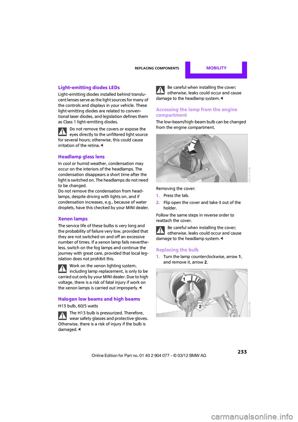
Removing the cover:
1.Press the tab.
2. Flip open the cover and take it out of the
holder.
Follow the same steps in reverse order to
reattach the cover.
Be careful when inst alling the cover;
otherwise, leaks could occur and cause
damage to the headlamp system. <
Replacing the bulb
1.Turn the lamp counterclockwise, arrow 1,
and remove it, arrow 2.
00320051004F004C00510048000300280047004C0057004C005200510003
Page 240 of 283
Replacing componentsMOBILITY
239
Adjusting the tire pressure
1.After driving approx. 3.1 miles/5 km or
10 minutes, stop at a suitable location.
2. Screw the connection hose 6 of the
compressor directly onto the tire valve.
3. Insert the plug 5 into the power socket in
the vehicle interior.
4. Adjust tire pressure to 1.8 bar/26 psi. With
the engine running:
> To increase the inflatio n pressure: switch on
the compressor. To check the current infla-
tion pressure, switch off the compressor.
Do not run the compressor for longer
than 10 minutes; otherwise, the
device will overheat and possibly be
damaged. <
> To decrease the inflation pressure: press the
release button 9.
If the tire cannot ma intain the inflation
pressure, drive the vehicle again, refer to
Distributing the sealan t. Then repeat steps
1to4.
If an inflation pressure of 1.8 bar/26 psi still
cannot be reached, then the tire is too heavily
damaged. Contact your nearest MINI dealer. <
Driving on
Do not exceed the permitted maximum
speed of 50 mph/80 km/h; doing so may
result in an accident. <
Replace the defective tire as soon as possible
and have the new wheel/tire assembly
balanced.
Have the Mobility Kit refilled.
Changing wheels
Run-flat tires
Tire change for run-flat tires:
> Prepare for tire change, page 240
> Jack up vehicle, page 241
> Tighten lug bolts, page 241
Space-saver spare tire
Tire change with space-saver spare tire:
>Remove the space-saver spare tire,
page 239
> Prepare for tire change, page 240
> Jack up vehicle, page 241
> Mount space-saver spare tire, page 241
> Tighten lug bolts, page 241
> Drive with space-saver spare tire, page 240
Removing the space-saver spare tire
The screw connection of the space-saver spare
tire is under the floor mat in the cargo area, on
the base of the storage compartment for the tire
change set.
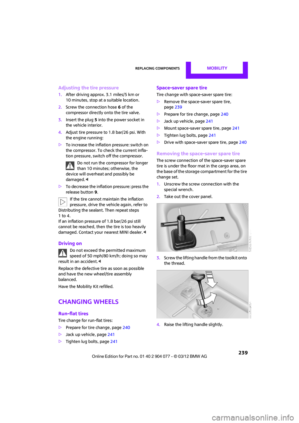
1. Unscrew the screw connection with the
special wrench.
2. Take out the cover panel.
3. Screw the lifting handle from the toolkit onto
the thread.
4. Raise the lifting handle slightly.
00320051004F004C00510048000300280047004C0057004C005200510003
Page 241 of 283
MOBILITYReplacing components
240
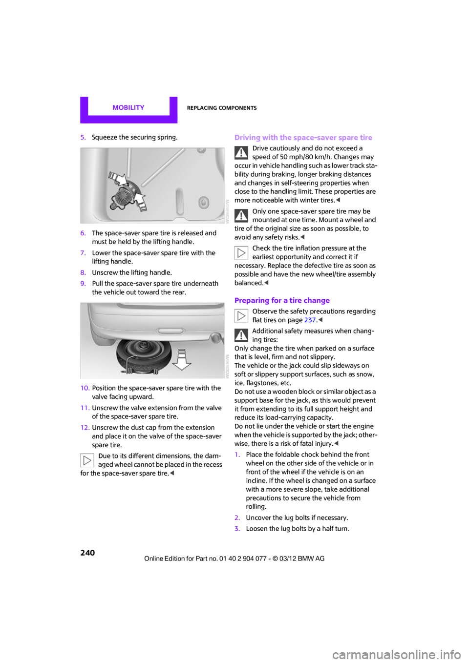
5.Squeeze the securing spring.
6. The space-saver spare tire is released and
must be held by the lifting handle.
7. Lower the space-saver spare tire with the
lifting handle.
8. Unscrew the lifting handle.
9. Pull the space-saver spare tire underneath
the vehicle out toward the rear.
10. Position the space-save r spare tire with the
valve facing upward.
11. Unscrew the valve extension from the valve
of the space-saver spare tire.
12. Unscrew the dust cap from the extension
and place it on the valve of the space-saver
spare tire.
Due to its different dimensions, the dam-
aged wheel cannot be placed in the recess
for the space-saver spare tire.
speed of 50 mph/80 km/h. Changes may
occur in vehicle handling such as lower track sta-
bility during braking, longer braking distances
and changes in self-steering properties when
close to the handling limit. These properties are
more noticeable with winter tires. <
Only one space-saver spare tire may be
mounted at one time. Mount a wheel and
tire of the original size as soon as possible, to
avoid any safety risks. <
Check the tire inflation pressure at the
earliest opportunity and correct it if
necessary. Replace the defe ctive tire as soon as
possible and have the ne w wheel/tire assembly
balanced. <
Preparing for a tire change
Observe the safety precautions regarding
flat tires on page 237.<
Additional safety measures when chang-
ing tires:
Only change the tire wh en parked on a surface
that is level, firm and not slippery.
The vehicle or the jack could slip sideways on
soft or slippery support surfaces, such as snow,
ice, flagstones, etc.
Do not use a wooden block or similar object as a
support base for the jack, as this would prevent
it from extending to its full support height and
reduce its load-carrying capacity.
Do not lie under the vehicle or start the engine
when the vehicle is supported by the jack; other-
wise, there is a risk of fatal injury. <
1. Place the foldable chock behind the front
wheel on the other side of the vehicle or in
front of the wheel if the vehicle is on an
incline. If the wheel is changed on a surface
with a more severe sl ope, take additional
precautions to secure the vehicle from
rolling.
2. Uncover the lug bolts if necessary.
3. Loosen the lug bolts by a half turn.
00320051004F004C00510048000300280047004C0057004C005200510003
Page 243 of 283
MOBILITYReplacing components
242
Starting-aid terminals
Only charge the battery in the vehicle when the
engine is off. Connections, refer to Jump-start-
ing on page 243.
Charger
The use of a charger ensures that the battery has
a sufficient charge even when it is used for fre-
quent short-distance driv es, for example. Charg-
ers that have been developed especially for the
vehicle and adapted to the vehicle electrical
system are available at your MINI dealer.
Disposal
After replacing old batteries, return the
used batteries to your MINI dealer or to a
recycling center. Maintain the battery in an
upright position for transport and storage.
Always secure the battery against tipping over
during transport. <
Power failure
After a temporary power loss, some equipment
may not be fully functional and may require
initialization. Individual se ttings are also lost and
must be reprogrammed:
> Time and date
These values must be updated, page 76.
> Onboard monitor
Operability must be waited for, page124.
Indicator and warning lamps
Lights up in red:
Battery is no longer being charged.
Alternator malfunction.
Switch off all unnecessary electrical consumers.
Have the battery checked without delay. Lights up in yellow:
Battery charge level very low, battery
aged, or battery not securely con-
nected.
Charge it by taking a long er drive or by using an
external charger. If the display appears again,
have the battery checked as soon as possible.
Fuses
Do not attempt to repair a blown fuse or
replace it with a fuse of a different color or
Ampere rating. To do this could cause a fire in
the vehicle resulting from a circuit overload.
Have fuses replaced by your MINI dealer. <
A fuse assignment diag ram is located on the
inside of the fuse box cover panels.
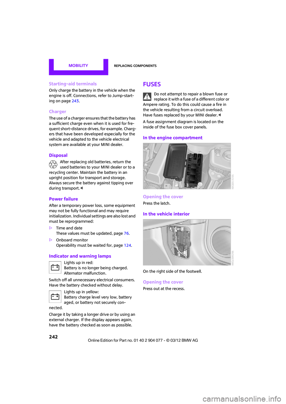
In the engine compartment
Opening the cover
Press the latch.
In the vehicle interior
On the right side of the footwell.
Opening the cover
Press out at the recess.
00320051004F004C00510048000300280047004C0057004C005200510003
Page 244 of 283
Giving and receiving assistanceMOBILITY
243
Giving and receiving assistance
Vehicle equipment
In this chapter, all production, country, and
optional equipment that is offered in the model
range is described. Equipment is also described
that is not available because of, for example,
selected options or count ry version. This also
applies to safety related functions and systems.
Roadside Assistance
Roadside Assistance is available by phone
24 hours a day in many countries. You can
receive assistance there in the event of an
emergency.
First aid pouch
Some of the articles co ntained in the first aid
pouch have a limited se rvice life. Therefore,
check the expiration dates of the contents
regularly and replace any items in good time, if
necessary.
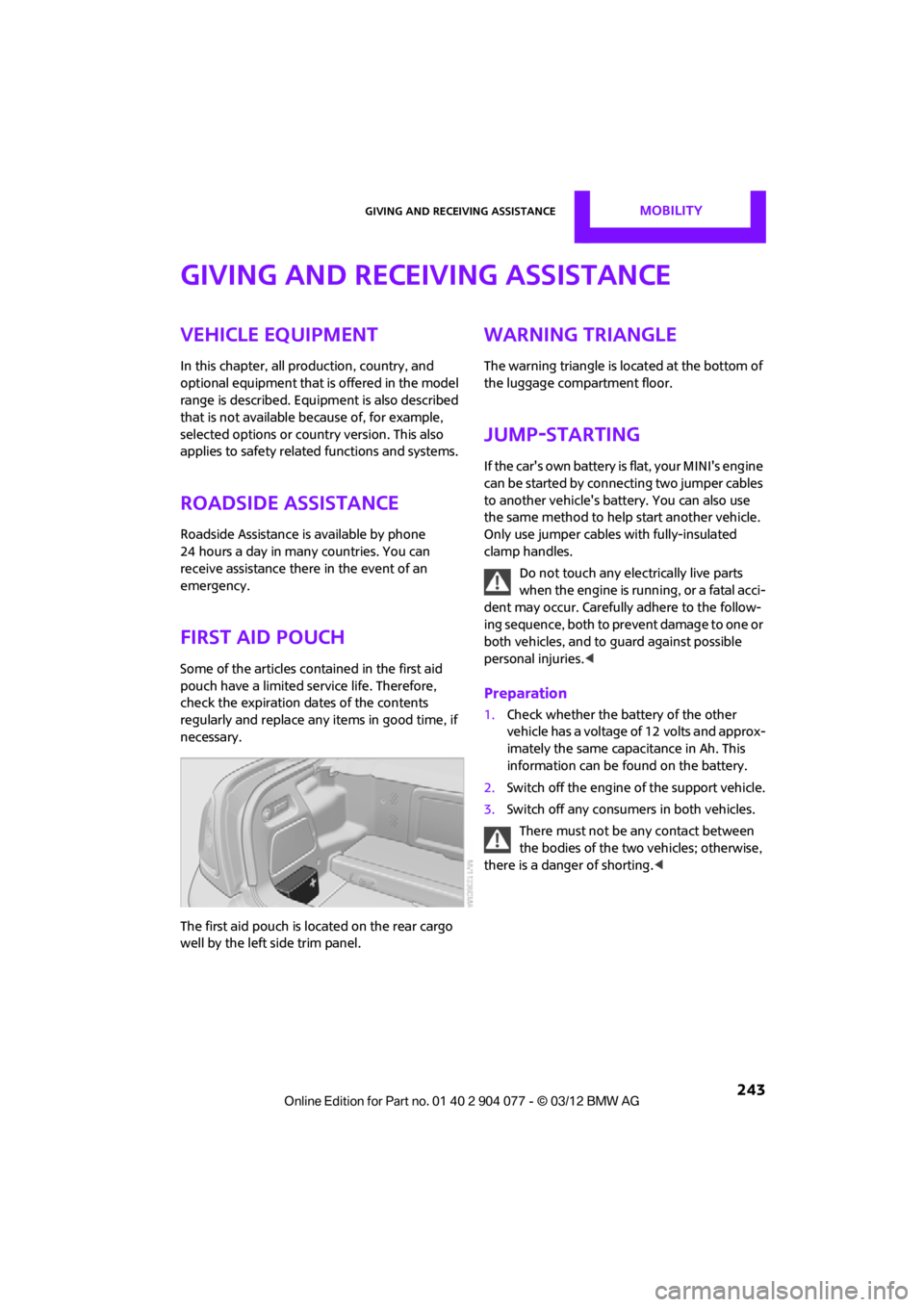
The first aid pouch is located on the rear cargo
well by the left side trim panel.
Warning triangle
The warning triangle is located at the bottom of
the luggage compartment floor.
Jump-starting
If the car's own battery is flat, your MINI's engine
can be started by connecting two jumper cables
to another vehicle's battery. You can also use
the same method to help start another vehicle.
Only use jumper cables with fully-insulated
clamp handles.
Do not touch any electrically live parts
w hen the e ngin e is run ning, or a fatal acci-
dent may occur. Carefully adhere to the follow-
ing sequence, both to prevent damage to one or
both vehicles, and to guard against possible
personal injuries. <
Preparation
1.Check whether the battery of the other
vehicle has a voltage of 12 volts and approx-
imately the same capacitance in Ah. This
information can be found on the battery.
2. Switch off the engine of the support vehicle.
3. Switch off any consumers in both vehicles.
There must not be any contact between
the bodies of the two vehicles; otherwise,
there is a danger of shorting. <
00320051004F004C00510048000300280047004C0057004C005200510003