high beam MINI COUPE ROADSTER CONVERTIBLE 2014 Owners Manual
[x] Cancel search | Manufacturer: MINI, Model Year: 2014, Model line: COUPE ROADSTER CONVERTIBLE, Model: MINI COUPE ROADSTER CONVERTIBLE 2014Pages: 224, PDF Size: 5.4 MB
Page 56 of 224
To save battery power when the engine is off,
switch off the ignition and any unnecessary
electronic systems/power consumers.
Radio ready state and ignition off All indicator and warning lamps in the displays
go out.
The ignition switches off automatically when
the driver's door is opened. Pressing the Start/
Stop button again switches the ignition back
on.
For example, the ignition is not switched off in
the following situations:▷Depress the clutch or brake pedal.▷The low beams are switched on
Starting the engine
General information Enclosed areas
Do not let the engine run in enclosed
areas; otherwise, breathing of exhaust fumes
may lead to loss of consciousness and death.
The exhaust gases contain carbon monoxide,
an odorless and colorless but highly toxic gas. ◀
Unattended vehicle
Do not leave the car unattended with the
engine running; otherwise, it presents a poten‐
tial source of danger.
Before leaving the car with the engine running,
shift to neutral or engage transmission posi‐
tion P and set the handbrake firmly; otherwise,
the vehicle may begin to roll. ◀
Frequent starting in quick succession
Avoid repeated futile attempts at starting
the car and avoid starting the car frequently in
quick succession. Otherwise, the fuel is not
burned or is inadequately burned, and there is
the danger of overheating and damaging the
catalytic converter. ◀
Do not wait for the engine to warm-up while
the vehicle remains stationary; start driving
right away, but at moderate engine speeds.
Do not depress the accelerator when starting
the engine.
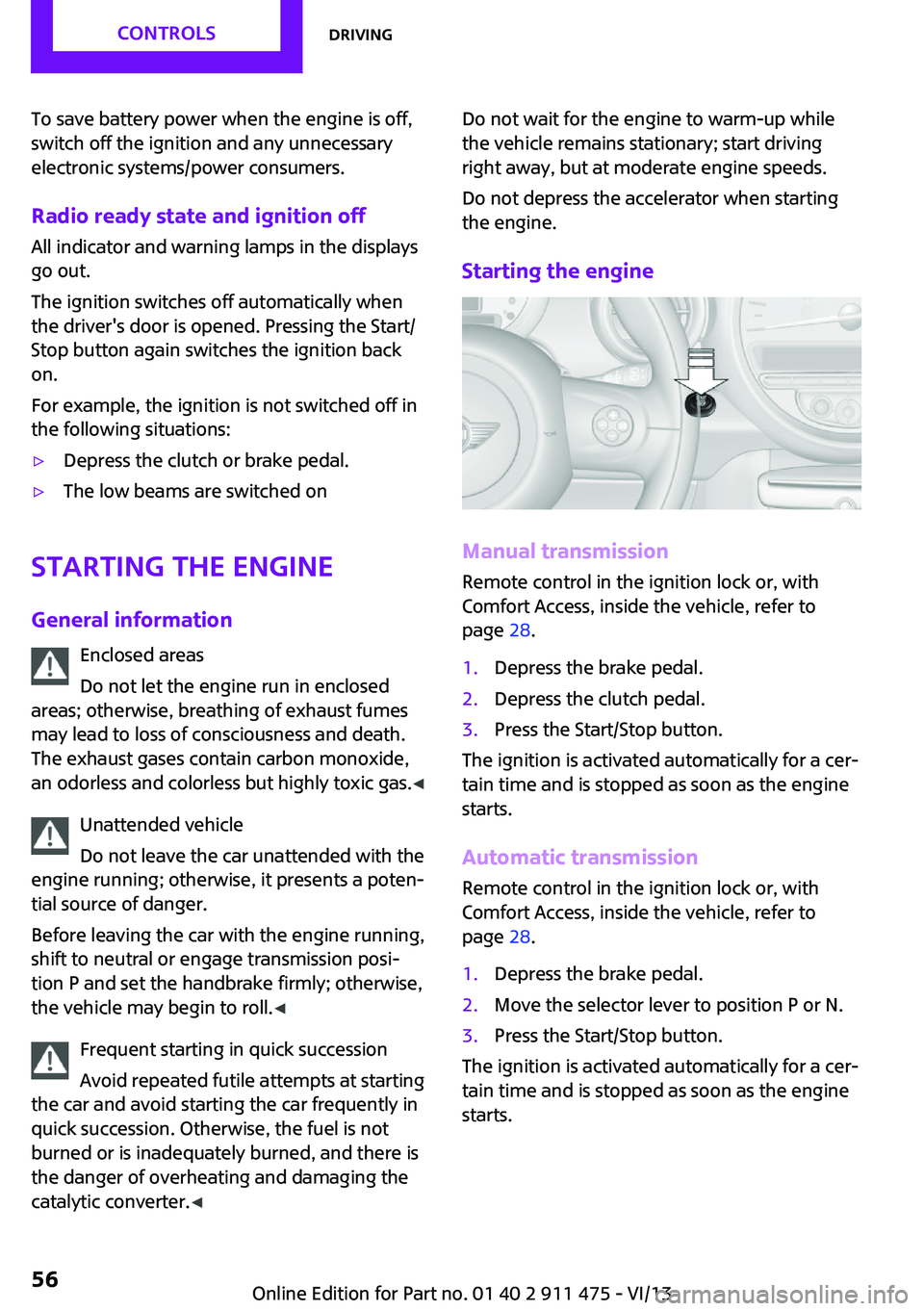
Starting the engine
Manual transmission
Remote control in the ignition lock or, with
Comfort Access, inside the vehicle, refer to
page 28.
1.Depress the brake pedal.2.Depress the clutch pedal.3.Press the Start/Stop button.
The ignition is activated automatically for a cer‐
tain time and is stopped as soon as the engine
starts.
Automatic transmission
Remote control in the ignition lock or, with
Comfort Access, inside the vehicle, refer to
page 28.
1.Depress the brake pedal.2.Move the selector lever to position P or N.3.Press the Start/Stop button.
The ignition is activated automatically for a cer‐
tain time and is stopped as soon as the engine
starts.
Seite 56ControlsDriving56
Online Edition for Part no. 01 40 2 911 475 - VI/13
Page 58 of 224

Turn signal, high beams,
headlamp flasher1Turn signal2Switching on the high beams3Switching off the high beams/headlamp
flasher
Turn signal
Press the lever beyond the resistance point.
To switch off manually, press the lever to the
resistance point.
Unusually rapid flashing of the indicator lamp
indicates that a turn signal bulb has failed.
Signaling a turn briefly Press the lever to the resistance point and hold
it there for as long as you want the turn signal
to flash.
Triple turn signal activation Press the lever to the resistance point.
The turn signal flashes three times.
This function can be activated or deactivated:1.Switch on the ignition, refer to page 55.2.Press the button on the turn indicator lever
repeatedly until "SET/INFO" is displayed.3.Press and hold the button until the display
changes.4.Press the button repeatedly until the sym‐
bol and "SET" are displayed.5.Press and hold the button until the display
changes.6.Press the button repeatedly until the sym‐
bol shown is displayed, arrow.7.Press and hold the button until the display
changes.8.Press the button to select:Seite 58ControlsDriving58
Online Edition for Part no. 01 40 2 911 475 - VI/13
Page 75 of 224

When the daytime running lights are activated,
the low beams are always switched on in
switch position 3 when the ignition is switched
on.
The exterior lighting goes out automatically af‐
ter the vehicle is switched off.
High beams/roadside parking lamps1Turn signal/roadside parking lamp2Switching on the high beams3Switching off the high beams/headlamp
flasher
To assist in parking, the vehicle can be illumi‐
nated on one side; note the country-specific
regulations.
The roadside parking lamps drain the battery.
Therefore, do not leave them on for unduly
long periods of time; otherwise, the battery
might not have enough power to start the en‐
gine.
Switching on the roadside parking lamp
To switch on the roadside parking lamp on the
left or right, press the turn indicator lever up or
down after switching off the vehicle, arrow 1.
Switching off the roadside parking lamp
Press the lever up or down to the resistance
point.
Daytime running lights
The daytime running lights light up in switch
position 0, 1, or 3 when the ignition is switched
on.
The exterior lighting goes out automatically af‐
ter the vehicle is switched off.
In switch position 1, the parking lamps light up
after the ignition is switched off.
Activating/deactivating1.Switch on the ignition, refer to page 55.2.Press the button on the turn indicator lever
repeatedly until "SET/INFO" is displayed.3.Press and hold the button until the display
changes.4.Press the button repeatedly until the sym‐
bol and "SET" are displayed.5.Press and hold the button until the display
changes.Seite 75LampsControls75
Online Edition for Part no. 01 40 2 911 475 - VI/13
Page 77 of 224

Depending on the steering angle and other pa‐
rameters, the light from the headlamp follows
the course of the road.
Activating With the ignition switch on, turn the light switch
to position 3, refer to page 74.
To avoid blinding oncoming traffic, the Adap‐
tive Light Control does not swivel to the driver's
side when the vehicle is at a standstill.
When driving in reverse, Adaptive Light Control
is not active.
Malfunction The warning lamp lights up. Adaptive
Light Control is malfunctioning or has
failed. Have the system checked as
soon as possible.
More information, refer to page 196.
Fog lamps
MINI Coupe, MINI Roadster1Fog lamps2Rear fog lamp
To switch on/off, press the respective button.
MINI Convertible▷To switch on the front fog lamps:
Press the switch upward.▷To switch on the rear fog lamp:
Press the switch downward.
To switch off, press the respective switch up‐
ward or downward again.
Fog lamps
The parking lamps or low beams must be
switched on. The green indicator lamp lights up
when the front fog lamps are switched on.
Depending on the vehicle equipment, the front
fog lamps are switched off when the headlamp
flasher or the high beams are activated.
If the automatic headlamp control is activated,
refer to page 74, the low beams are switched
on automatically when the front fog lamps are
switched on.
Rear fog lampThe low beams or parking lamps with front fog
lamps must be switched on. The yellow indica‐
tor lamp lights up when the rear fog lamp is
switched on.
Instrument lighting The parking lamps or low beams must beswitched on to adjust the brightness. The
brightness is increased to a certain limit and is then reduced again.
Seite 77LampsControls77
Online Edition for Part no. 01 40 2 911 475 - VI/13
Page 177 of 224
Use a clean tissue, cloth or something similar,
or hold the bulb by its base. ◀
Caring for the headlamps, refer to page 192.
For bulb replacement that is not described
here, please contact the service center or a
workshop that works according to the repair
procedures of the manufacturer with corre‐
spondingly trained personnel.
For checking and adjusting headlamp aim,
please contact your MINI dealer.
Light-emitting diodes LEDs Light-emitting diodes installed behind translu‐
cent lenses serve as the light source for many
of the controls and displays in the vehicle.
These light-emitting diodes, which operate us‐
ing a concept similar to that applied in conven‐
tional lasers, are officially designated as Class 1
light-emitting diodes.
Do not remove the covers
Do not remove the covers, and never
stare into the unfiltered light for several hours;
otherwise, irritation of the retina could result. ◀
Headlamp glass
Condensation can form on the inside of the
headlamps in cool or humid weather. When the
light is switched on, the condensation evapo‐
rates after a short time. The headlamps do not
need to be changed.
If the condensation in the headlamps does not
evaporate after trips with the lights switched
on, and the amount of moisture in the head‐
lamps increases, for example if water droplets
form, have them checked by your service cen‐
ter.
Bi-xenon headlamps These bulbs have a very long life and the likeli‐
hood of failure is very low, provided that they
are not switched on and off excessively. If a
bulb should nevertheless fail, you can continuedriving cautiously with the front fog lamps, pro‐
vided this is permitted by local laws.
Do not perform work/bulb replacement
on xenon headlamps
Have any work on the xenon lighting system,
including bulb replacement, performed only by
a service center.
Due to the high voltage present in the system,
there is the danger of fatal injuries if work is
carried out improperly. ◀
Front lamps, bulb replacement
Halogen low beams and high beams
Bulb H13, 60/55 watt
Wear protective goggles and gloves
Halogen bulbs are pressurized. Therefore,
wear protective goggles and gloves. Otherwise,
there is a danger of injuries if the bulb is acci‐
dentally damaged during replacement. ◀
Attach the cover carefully
When attaching the cover, proceed care‐
fully; otherwise, leaks may occur, causing dam‐
age to the headlamp system. ◀
Access to the bulbs through the engine
compartment
Follow the general instructions on lamps and
bulbs, refer to page 176.
Low beam/high beam bulbs can be changed
from the engine compartment.Seite 177Replacing componentsMobility177
Online Edition for Part no. 01 40 2 911 475 - VI/13
Page 196 of 224
Indicator/warning lampsVehicle equipment
This chapter describes all series equipment as
well as country-specific and special equipment
offered for this model series.Therefore, it alsodescribes equipment that may not be found in
your vehicle, for instance due to the selected
special equipment or the country version. This
also applies to safety-related functions and sys‐
tems.
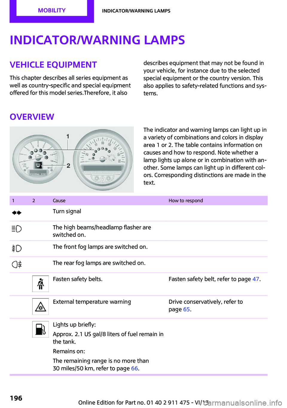
Overview
The indicator and warning lamps can light up in
a variety of combinations and colors in display
area 1 or 2. The table contains information on
causes and how to respond. Note whether a
lamp lights up alone or in combination with an‐
other. Some lamps can light up in different col‐
ors. Corresponding distinctions are made in the
text. 12CauseHow to respondTurn signalThe high beams/headlamp flasher are
switched on.The front fog lamps are switched on.The rear fog lamps are switched on.Fasten safety belts.Fasten safety belt, refer to page 47.External temperature warningDrive conservatively, refer to
page 65.Lights up briefly:
Approx. 2.1 US gal/8 liters of fuel remain in
the tank.
Remains on:
The remaining range is no more than
30 miles/50 km, refer to page 66.Seite 196MobilityIndicator/warning lamps196
Online Edition for Part no. 01 40 2 911 475 - VI/13
Page 206 of 224
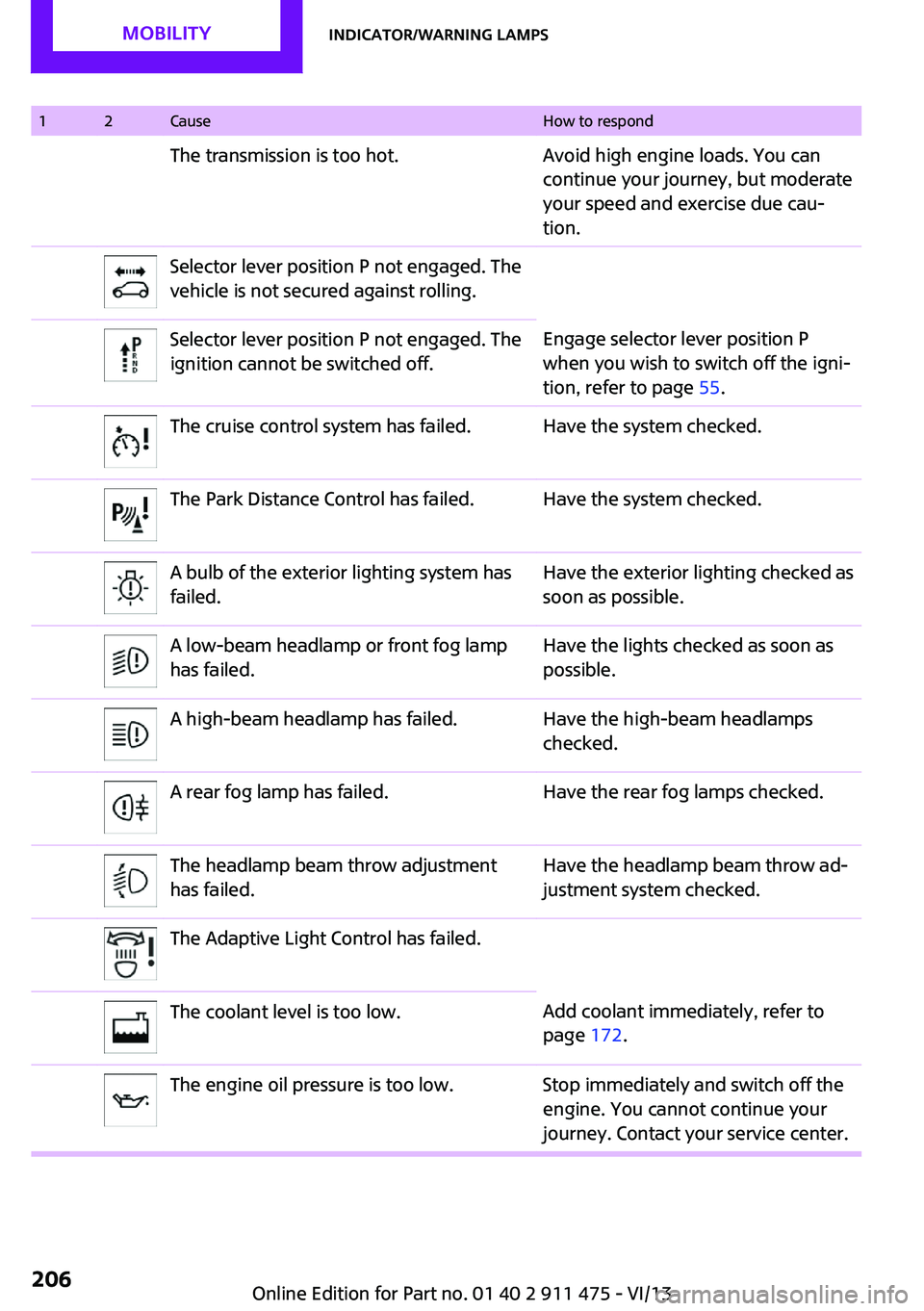
12CauseHow to respondThe transmission is too hot.Avoid high engine loads. You can
continue your journey, but moderate
your speed and exercise due cau‐
tion.Selector lever position P not engaged. The
vehicle is not secured against rolling.Selector lever position P not engaged. The
ignition cannot be switched off.Engage selector lever position P
when you wish to switch off the igni‐
tion, refer to page 55.The cruise control system has failed.Have the system checked.The Park Distance Control has failed.Have the system checked.A bulb of the exterior lighting system has
failed.Have the exterior lighting checked as
soon as possible.A low-beam headlamp or front fog lamp
has failed.Have the lights checked as soon as
possible.A high-beam headlamp has failed.Have the high-beam headlamps
checked.A rear fog lamp has failed.Have the rear fog lamps checked.The headlamp beam throw adjustment
has failed.Have the headlamp beam throw ad‐
justment system checked.The Adaptive Light Control has failed.The coolant level is too low.Add coolant immediately, refer to
page 172.The engine oil pressure is too low.Stop immediately and switch off the
engine. You cannot continue your
journey. Contact your service center.Seite 206MobilityIndicator/warning lamps206
Online Edition for Part no. 01 40 2 911 475 - VI/13
Page 215 of 224
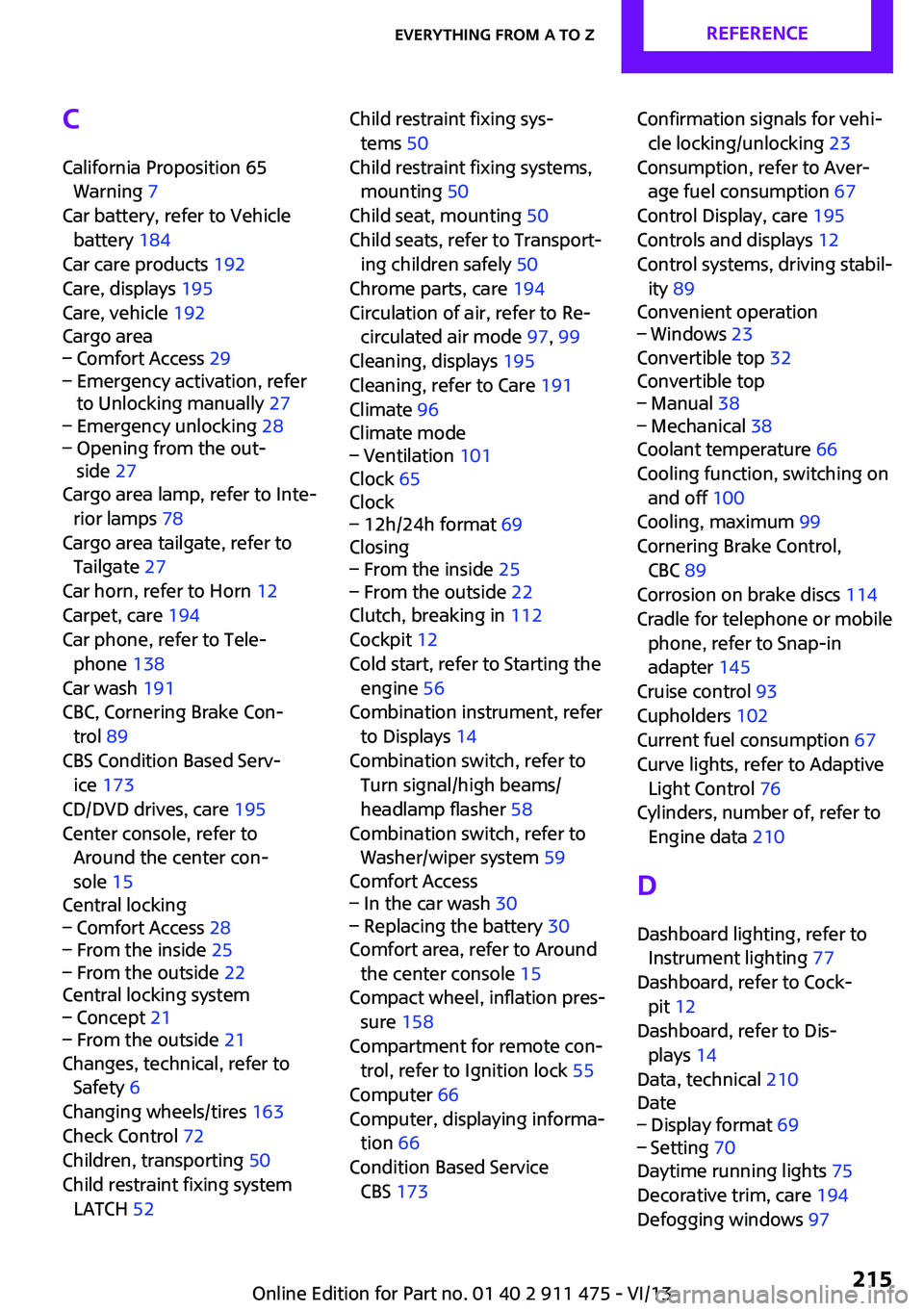
C
California Proposition 65 Warning 7
Car battery, refer to Vehicle battery 184
Car care products 192
Care, displays 195
Care, vehicle 192
Cargo area– Comfort Access 29– Emergency activation, refer
to Unlocking manually 27– Emergency unlocking 28– Opening from the out‐
side 27
Cargo area lamp, refer to Inte‐
rior lamps 78
Cargo area tailgate, refer to Tailgate 27
Car horn, refer to Horn 12
Carpet, care 194
Car phone, refer to Tele‐ phone 138
Car wash 191
CBC, Cornering Brake Con‐ trol 89
CBS Condition Based Serv‐ ice 173
CD/DVD drives, care 195
Center console, refer to Around the center con‐
sole 15
Central locking
– Comfort Access 28– From the inside 25– From the outside 22
Central locking system
– Concept 21– From the outside 21
Changes, technical, refer to
Safety 6
Changing wheels/tires 163
Check Control 72
Children, transporting 50
Child restraint fixing system LATCH 52
Child restraint fixing sys‐
tems 50
Child restraint fixing systems, mounting 50
Child seat, mounting 50
Child seats, refer to Transport‐ ing children safely 50
Chrome parts, care 194
Circulation of air, refer to Re‐ circulated air mode 97, 99
Cleaning, displays 195
Cleaning, refer to Care 191
Climate 96
Climate mode– Ventilation 101
Clock 65
Clock
– 12h/24h format 69
Closing
– From the inside 25– From the outside 22
Clutch, breaking in 112
Cockpit 12
Cold start, refer to Starting the engine 56
Combination instrument, refer to Displays 14
Combination switch, refer to Turn signal/high beams/
headlamp flasher 58
Combination switch, refer to Washer/wiper system 59
Comfort Access
– In the car wash 30– Replacing the battery 30
Comfort area, refer to Around
the center console 15
Compact wheel, inflation pres‐ sure 158
Compartment for remote con‐ trol, refer to Ignition lock 55
Computer 66
Computer, displaying informa‐ tion 66
Condition Based Service CBS 173
Confirmation signals for vehi‐
cle locking/unlocking 23
Consumption, refer to Aver‐ age fuel consumption 67
Control Display, care 195
Controls and displays 12
Control systems, driving stabil‐ ity 89
Convenient operation– Windows 23
Convertible top 32
Convertible top
– Manual 38– Mechanical 38
Coolant temperature 66
Cooling function, switching on and off 100
Cooling, maximum 99
Cornering Brake Control, CBC 89
Corrosion on brake discs 114
Cradle for telephone or mobile phone, refer to Snap-in
adapter 145
Cruise control 93
Cupholders 102
Current fuel consumption 67
Curve lights, refer to Adaptive Light Control 76
Cylinders, number of, refer to Engine data 210
D
Dashboard lighting, refer to Instrument lighting 77
Dashboard, refer to Cock‐ pit 12
Dashboard, refer to Dis‐ plays 14
Data, technical 210
Date
– Display format 69– Setting 70
Daytime running lights 75
Decorative trim, care 194
Defogging windows 97
Seite 215Everything from A to ZReference215
Online Edition for Part no. 01 40 2 911 475 - VI/13
Page 217 of 224
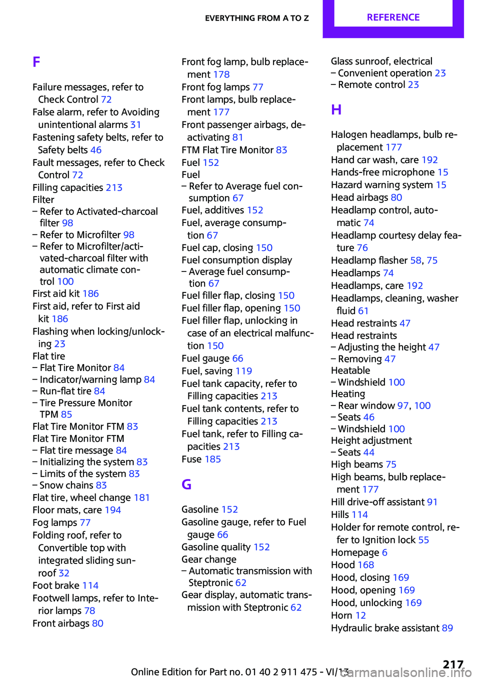
FFailure messages, refer to Check Control 72
False alarm, refer to Avoiding unintentional alarms 31
Fastening safety belts, refer to Safety belts 46
Fault messages, refer to Check Control 72
Filling capacities 213
Filter– Refer to Activated-charcoal
filter 98– Refer to Microfilter 98– Refer to Microfilter/acti‐
vated-charcoal filter with
automatic climate con‐
trol 100
First aid kit 186
First aid, refer to First aid kit 186
Flashing when locking/unlock‐ ing 23
Flat tire
– Flat Tire Monitor 84– Indicator/warning lamp 84– Run-flat tire 84– Tire Pressure Monitor
TPM 85
Flat Tire Monitor FTM 83
Flat Tire Monitor FTM
– Flat tire message 84– Initializing the system 83– Limits of the system 83– Snow chains 83
Flat tire, wheel change 181
Floor mats, care 194
Fog lamps 77
Folding roof, refer to Convertible top with
integrated sliding sun‐
roof 32
Foot brake 114
Footwell lamps, refer to Inte‐ rior lamps 78
Front airbags 80
Front fog lamp, bulb replace‐
ment 178
Front fog lamps 77
Front lamps, bulb replace‐ ment 177
Front passenger airbags, de‐ activating 81
FTM Flat Tire Monitor 83
Fuel 152
Fuel– Refer to Average fuel con‐
sumption 67
Fuel, additives 152
Fuel, average consump‐ tion 67
Fuel cap, closing 150
Fuel consumption display
– Average fuel consump‐
tion 67
Fuel filler flap, closing 150
Fuel filler flap, opening 150
Fuel filler flap, unlocking in case of an electrical malfunc‐
tion 150
Fuel gauge 66
Fuel, saving 119
Fuel tank capacity, refer to Filling capacities 213
Fuel tank contents, refer to Filling capacities 213
Fuel tank, refer to Filling ca‐ pacities 213
Fuse 185
G Gasoline 152
Gasoline gauge, refer to Fuel gauge 66
Gasoline quality 152
Gear change
– Automatic transmission with
Steptronic 62
Gear display, automatic trans‐
mission with Steptronic 62
Glass sunroof, electrical– Convenient operation 23– Remote control 23
H
Halogen headlamps, bulb re‐ placement 177
Hand car wash, care 192
Hands-free microphone 15
Hazard warning system 15
Head airbags 80
Headlamp control, auto‐ matic 74
Headlamp courtesy delay fea‐ ture 76
Headlamp flasher 58, 75
Headlamps 74
Headlamps, care 192
Headlamps, cleaning, washer fluid 61
Head restraints 47
Head restraints
– Adjusting the height 47– Removing 47
Heatable
– Windshield 100
Heating
– Rear window 97, 100– Seats 46– Windshield 100
Height adjustment
– Seats 44
High beams 75
High beams, bulb replace‐ ment 177
Hill drive-off assistant 91
Hills 114
Holder for remote control, re‐ fer to Ignition lock 55
Homepage 6
Hood 168
Hood, closing 169
Hood, opening 169
Hood, unlocking 169
Horn 12
Hydraulic brake assistant 89
Seite 217Everything from A to ZReference217
Online Edition for Part no. 01 40 2 911 475 - VI/13