display MINI Hardtop 2 Door 2004 User Guide
[x] Cancel search | Manufacturer: MINI, Model Year: 2004, Model line: Hardtop 2 Door, Model: MINI Hardtop 2 Door 2004Pages: 152, PDF Size: 1.41 MB
Page 59 of 152

57
OVERVIEW REPAIRS OPERATIONCONTROLS DATA INDEX
ONBOARD COMPUTER
*
Mode selection
With the ignition key in position 1 and higher,
you can use the button in the turn signal indi-
cator lever to retrieve information from the
onboard computer for display in the tachom-
eter. By pressing the button briefly, you can
call up a new function for display.
The displays appear in the following order:
Outside temperature, range, average con-
sumption and current consumption, aver-
age speed and current speed.
Starting with ignition key position 1, the
last active setting is displayed.
If the vehicle is equipped with a navi-
gation system, you will find more
information on the onboard computer in
the navigation system Owner's Manual.<
Outside temperature If the vehicle is equipped with a tachome-
ter, but not with an onboard computer, the
outside temperature is displayed.
You can have the units 6 or 7 set
by your MINI Dealer.<
Ice warning If the outside temperature falls below
approx. 37 7 / +36, the onboard com-
puter automatically switches to the outside
temperature display.
In addition, an acoustic signal can be heard
and the display flashes for a short time.
The ice warning does not exclude the
possibility that surface ice can form
at temperatures above 37 7 / +36, e.g.
on bridges and shaded roads.<
With navigation system option:
The temperature is displayed in the status
line of the navigation system, refer to the
Owner's Manual for the navigation system.Current vehicle speedIf the vehicle is equipped with a tachome-
ter, but not with an onboard computer, the
current vehicle speed is displayed.
With the ignition key in position 1 and
higher, you can use the button in the turn
signal indicator lever to call this up in the
tachometer display. Briefly press the but-
ton to switch the display from the outside
temperature to the current vehicle speed.
Page 60 of 152

58
ONBOARD COMPUTER
*
Range
The onboard computer bases its calcula-
tions for the cruising range on the driving
style and on the remaining fuel in the tank.
If the range displayed is less than
35 miles / 50 km, be sure to refuel;
otherwise engine functions are not guaran-
teed and damage could occur.
lever for a longer period.
The displayed average speed value and
consumption value are recalculated.
Any time spent when the vehicle is station-
ary and the engine is shut off is ignored for
the calculation.
You can have an other unit of mea-
surement set by your MINI Dealer.<
Current fuel consumption The current consumption value is calcu-
lated and displayed on the basis of your
driving style.
You can have a different unit of mea-
surement set by your MINI Dealer.<
Page 61 of 152
59
OVERVIEW REPAIRS OPERATIONCONTROLS DATA INDEX
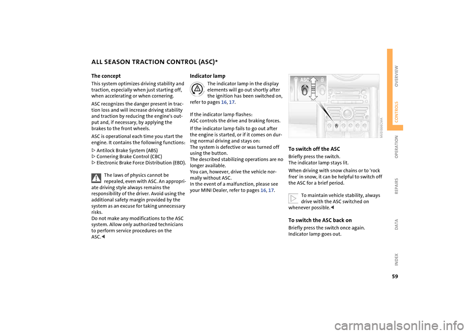
ALL SEASON TRACTION CONTROL (ASC)
*
The concept
This system optimizes driving stability and
traction, especially when just starting off,
when accelerating or when cornering.
ASC recognizes the danger present in trac-
tion loss and will increase driving stability
and traction by reducing the engine's out-
put and, if necessary, by applying the
brakes to the front wheels.
ASC is operational each time you start the
engine. It contains the following functions:
>Antilock Brake System (ABS)
>Cornering Brake Control (CBC)
>Electronic Brake Force Distribution (EBD).
The laws of physics cannot be
repealed, even with ASC. An appropri-
ate driving style always remains the
responsibility of the driver. Avoid using the
additional safety margin provided by the
system as an excuse for taking unnecessary
risks.
Do not make any modifications to the ASC
system. Allow only authorized technicians
to perform service procedures on the
ASC.<
Indicator lamp
The indicator lamp in the display
elements will go out shortly after
the ignition has been switched on,
refer to pages 16, 17.
If the indicator lamp flashes:
ASC controls the drive and braking forces.
If the indicator lamp fails to go out after
the engine is started, or if it comes on dur-
ing normal driving and stays on:
The system is defective or was turned off
using the button.
The described stabilizing operations are no
longer available.
You can, however, drive the vehicle nor-
mally without ASC.
In the event of a malfunction, please see
your MINI Dealer, refer to pages 16, 17.
To switch off the ASCBriefly press the switch.
The indicator lamp stays lit.
When driving with snow chains or to 'rock
free' in snow, it can be helpful to switch off
the ASC for a brief period.
To maintain vehicle stability, always
drive with the ASC switched on
whenever possible.
Page 62 of 152
60
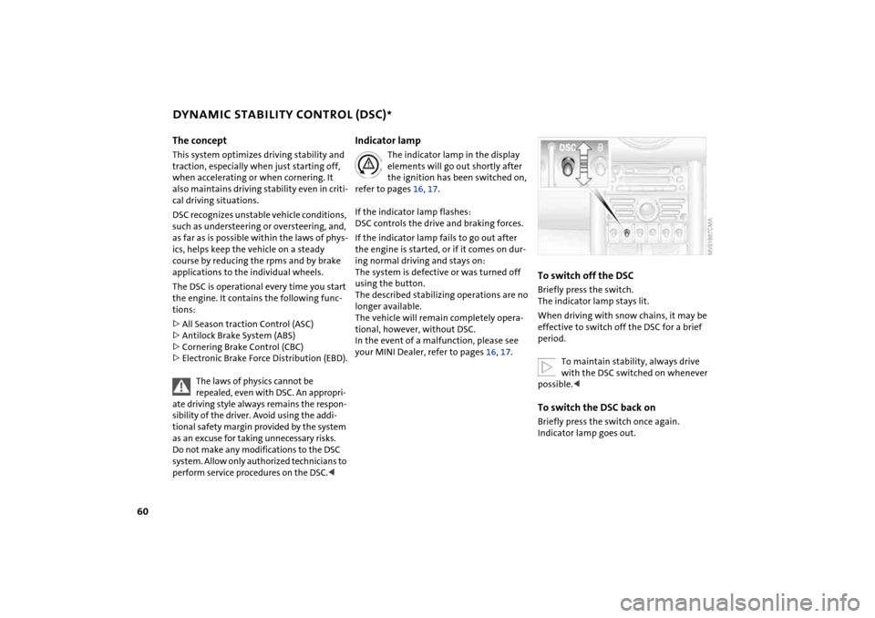
DYNAMIC STABILITY CONTROL (DSC)
*
The concept
This system optimizes driving stability and
traction, especially when just starting off,
when accelerating or when cornering. It
also maintains driving stability even in criti-
cal driving situations.
DSC recognizes unstable vehicle conditions,
such as understeering or oversteering, and,
as far as is possible within the laws of phys-
ics, helps keep the vehicle on a steady
course by reducing the rpms and by brake
applications to the individual wheels.
The DSC is operational every time you start
the engine. It contains the following func-
tions:
>All Season traction Control (ASC)
>Antilock Brake System (ABS)
>Cornering Brake Control (CBC)
>Electronic Brake Force Distribution (EBD).
The laws of physics cannot be
repealed, even with DSC. An appropri-
ate driving style always remains the respon-
sibility of the driver. Avoid using the addi-
tional safety margin provided by the system
as an excuse for taking unnecessary risks.
Do not make any modifications to the DSC
system. Allow only authorized technicians to
perform service procedures on the DSC.<
Indicator lamp
The indicator lamp in the display
elements will go out shortly after
the ignition has been switched on,
refer to pages 16, 17.
If the indicator lamp flashes:
DSC controls the drive and braking forces.
If the indicator lamp fails to go out after
the engine is started, or if it comes on dur-
ing normal driving and stays on:
The system is defective or was turned off
using the button.
The described stabilizing operations are no
longer available.
The vehicle will remain completely opera-
tional, however, without DSC.
In the event of a malfunction, please see
your MINI Dealer, refer to pages 16, 17.
To switch off the DSCBriefly press the switch.
The indicator lamp stays lit.
When driving with snow chains, it may be
effective to switch off the DSC for a brief
period.
To maintain stability, always drive
with the DSC switched on whenever
possible.
Page 64 of 152

62
FLAT TIRE MONITOR The conceptAs you drive, the Flat Tire Monitor keeps
track of the tire inflation pressure in all four
tires. The system alerts you when there is a
substantial pressure loss in one of the tires
relative to another.
The tire inflation pressures are monitored
based on the speeds of the four wheels in
relation to one another. A flat tire is
detected as the result of differences in cer-
tain speed ratios, and a warning is gener-
ated.System requirementsSo that the system can 'familiarize' itself
with the correct inflation pressure, please
do the following:
1. Check the tire inflation pressure in all
tires
2. Compare them with the inflation pres-
sure table, refer to page 88, and adjust
the pressures if necessary
3. Initializing the system.
System limitations
The Flat Tire Monitor cannot alert you
to severe and sudden tire damage
caused by external factors, nor does it
detect the gradual and minor loss of pres-
sure in all four tires.<
On the other hand, the following situations
could lead to a delayed detection of pres-
sure loss or to the system not functioning:
>Driving on snow-covered or slippery
roads
>Performance-oriented driving: slip at the
drive wheels, high rates of lateral accel-
eration
>When driving with snow chains, false
warnings and undetected pressure loss
may occur
>When driving with a space-saver spare
tire, the Flat Tire Monitor cannot func-
tion.
Initializing the system
The system must be re-initialized
immediately after changing a tire
and wheel, or after correcting the pressure
in any tire. This requires a bit of driving.<
1. Before a journey, start the engine, but do
not start driving
2. Press the button long enough for the
indicator lamp in the display elements to
light up for a few seconds
3. Drive off.
It takes a few minutes before the Flat Tire
Monitor can detect a flat tire and issue an
alert.
Do not initialize the system if you are
driving with snow chains or a space-
saver spare tire.<
Page 65 of 152

63
OVERVIEW REPAIRS OPERATIONCONTROLS DATA INDEX
FLAT TIRE MONITORFlat tireIndicator lamp:
The indicator lamp in the display
elements flashes. In addition, an
acoustic signal sounds.
1. Reduce speed and stop the vehicle with
caution. Avoid hard brake applications
and steering maneuvers
2. Determine which tire is damaged
If this cannot be determined, con-
tact your MINI Dealer.<
3. Replace the damaged tire, refer to
Changing tires on page 117, or repair the
flat tire using the MINI Moblity System,
refer to page 121.
Vehicles with Run Flat tires:
1. Reduce vehicle speed carefully to under
50 mph / 80 km/h. Avoid hard brake
applications and steering maneuvers.
Do not exceed a speed of 50 mph /
80 km/h
Since Run Flat tires are reinforced
on the flanks, it is usually not pos-
sible to detect a loss of pressure from
the outside, refer to Run Flat tires on
page 93.<
2. To continue driving, follow the instruc-
tions on driving with damaged tires on
page 93.System malfunctionIndicator lamp:
The symbol in the instrument clus-
ter lights up. The Flat Tire Monitor
is malfunctioning or out of order.
Please contact your MINI Dealer.
Page 67 of 152
65
OVERVIEW REPAIRS OPERATIONCONTROLS DATA INDEX
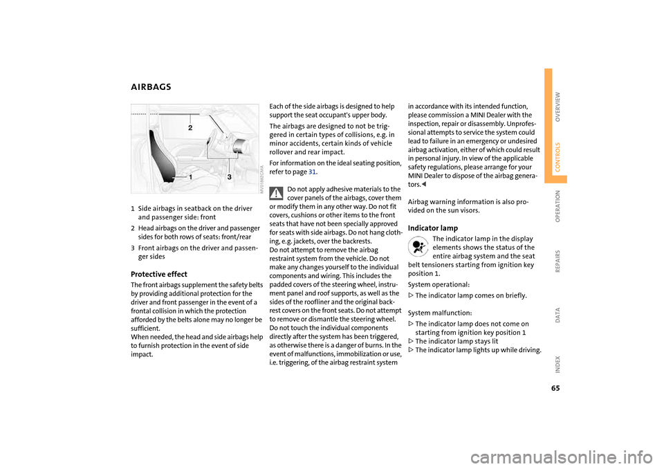
AIRBAGS1Side airbags in seatback on the driver
and passenger side: front
2Head airbags on the driver and passenger
sides for both rows of seats: front/rear
3Front airbags on the driver and passen-
ger sidesProtective effectThe front airbags supplement the safety belts
by providing additional protection for the
driver and front passenger in the event of a
frontal collision in which the protection
afforded by the belts alone may no longer be
sufficient.
When needed, the head and side airbags help
to furnish protection in the event of side
impact.
Each of the side airbags is designed to help
support the seat occupant's upper body.
The airbags are designed to not be trig-
gered in certain types of collisions, e.g. in
minor accidents, certain kinds of vehicle
rollover and rear impact.
For information on the ideal seating position,
refer to page 31.
Do not apply adhesive materials to the
cover panels of the airbags, cover them
or modify them in any other way. Do not fit
covers, cushions or other items to the front
seats that have not been specially approved
for seats with side airbags. Do not hang cloth-
ing, e. g. jackets, over the backrests.
Do not attempt to remove the airbag
restraint system from the vehicle. Do not
make any changes yourself to the individual
components and wiring. This includes the
padded covers of the steering wheel, instru-
ment panel and roof supports, as well as the
sides of the roofliner and the original back-
rest covers on the front seats. Do not attempt
to remove or dismantle the steering wheel.
Do not touch the individual components
directly after the system has been triggered,
as otherwise there is a danger of burns. In the
event of malfunctions, immobilization or use,
i.e. triggering, of the airbag restraint system
in accordance with its intended function,
please commission a MINI Dealer with the
inspection, repair or disassembly. Unprofes-
sional attempts to service the system could
lead to failure in an emergency or undesired
airbag activation, either of which could result
in personal injury. In view of the applicable
safety regulations, please arrange for your
MINI Dealer to dispose of the airbag genera-
tors.<
Airbag warning information is also pro-
vided on the sun visors.Indicator lamp
The indicator lamp in the display
elements shows the status of the
entire airbag system and the seat
belt tensioners starting from ignition key
position 1.
System operational:
>The indicator lamp comes on briefly.
System malfunction:
>The indicator lamp does not come on
starting from ignition key position 1
>The indicator lamp stays lit
>The indicator lamp lights up while driving.
Page 72 of 152

70
AUTOMATIC CLIMATE CONTROL
*
1Air onto the windshield and onto the
side windows
2Air for the upper body area72
3Air for the front and rear footwells
4Rear window defroster and windshield
heating715Interior temperature sensor,
please keep clear and unobstructed
6Recirculated air mode71
7Air conditioning71
8Automatic air distribution and
supply71
9Switching the automatic climate control
on/off7110 Temperature71
11 Display for temperature and air
supply71
12 Blower for air supply72
13 Defrosting and demisting the wind-
shield and side windows72
14 Individual air distribution72
Page 73 of 152
71
OVERVIEW REPAIRS OPERATIONCONTROLS DATA INDEX
AUTOMATIC CLIMATE CONTROL
*
Automatic air distribution and supply
Automatic program (AUTO):
Indicator lamp lights up.
Automatic adjustment of the air distribu-
tion and supply, and adaptation of the
specified temperatures to external influ-
ences, i.e. outside temperature and sun-
light.
In the automatic program (AUTO), the air
conditioner is activated automatically.
You can change the unit from 6 to
7 by keeping extended pressure on
the button.<
Switching the automatic climate
control on/off
The blower, heating and air condi-
tioner are switched off.
To switch the automatic climate control on
again: Press any button of the automatic
climate control.
Air conditioning
Air conditioner switched on: indi-
cator lamp lights up.
The air is cooled and dehumidified and –
depending on the temperature setting –
rewarmed.
In the automatic program (AUTO), the air
conditioner is activated automatically.
Condensation on the windows is reduced
when the air conditioning is turned on.
Condensation forms in the air condi-
tioning system during operation, and
then exits under the vehicle. Traces of con-
densed water on the ground are therefore
normal.
cle is blocked: indicator lamp lights
up.
The air within the vehicle is recirculated.
In the automatic program (AUTO) in hot
weather conditions, the recirculated air
mode is activated temporarily to enable
faster cooling.
Do not run the recirculated air mode
over a longer period of time, as the air
quality in the vehicle's interior will other-
wise diminish.<
If the windows fog up in the recircu-
lated air mode, turn the recirculated
air mode off and if necessary increase the
air supply.<
Rear window defroster and windshield
heating*
Rear window defroster and wind-
shield heating switched on:
Indicator lamp lights up.
As long as the indicator lamp is lit, the
heating operates at high power output –
rapid defrosting.
Indicator lamp goes out.
The heating continues to run with reduced
power output and then switches itself off
automatically.
Temperature
Setting the temperature:
Move or turn the wheel in the
appropriate direction to increase
the temperature step by step.
The figures in the display provide a general
indication of interior temperature. When
you start the vehicle, the system ensures
that the selected temperature is achieved
as quickly as possible and then maintained.
Permanent heating with maximum
power output at temperature selec-
tion HI. Permanent cooling at LO.<
Page 93 of 152
91
OVERVIEW REPAIRSOPERATIONCONTROLS DATA INDEX
TIRE CONDITION Tire tread Inspect your tires frequently for tread wear,
signs of damage and for foreign objects
lodged in the tread. Check the tread depth.
The tread depth should not fall below
1/8 in / 3 mm.
Below 1/8 in / 3 mm tread pattern depth,
there is an increased risk of hydroplaning,
even at relatively moderate speeds and
with only small amounts of water on the
road.
Below a tread depth of 1/6 in / 4 mm, win-
ter tires display a perceptible decrease in
their ability to cope with winter driving
conditions, and should be replaced in the
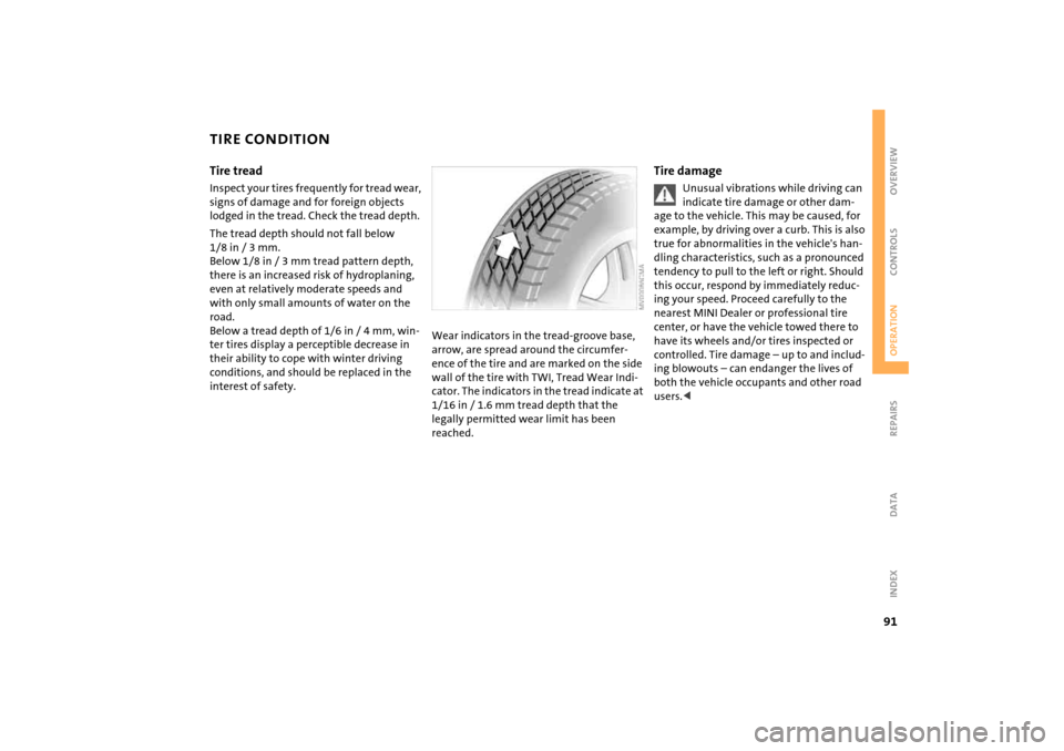
interest of safety.Wear indicators in the tread-groove base,
arrow, are spread around the circumfer-
ence of the tire and are marked on the side
wall of the tire with TWI, Tread Wear Indi-
cator. The indicators in the tread indicate at
1/16 in / 1.6 mm tread depth that the
legally permitted wear limit has been
reached.
Tire damage
Unusual vibrations while driving can
indicate tire damage or other dam-
age to the vehicle. This may be caused, for
example, by driving over a curb. This is also
true for abnormalities in the vehicle's han-
dling characteristics, such as a pronounced
tendency to pull to the left or right. Should
this occur, respond by immediately reduc-
ing your speed. Proceed carefully to the
nearest MINI Dealer or professional tire
center, or have the vehicle towed there to
have its wheels and/or tires inspected or
controlled. Tire damage – up to and includ-
ing blowouts – can endanger the lives of
both the vehicle occupants and other road
users.<