key MINI Hardtop 2 Door 2005 Owner's Guide
[x] Cancel search | Manufacturer: MINI, Model Year: 2005, Model line: Hardtop 2 Door, Model: MINI Hardtop 2 Door 2005Pages: 165, PDF Size: 2.32 MB
Page 59 of 165

57
OVERVIEW REPAIRS OPERATIONCONTROLS DATA INDEX
PARKING LAMPS/LOW BEAMS Switching on the parking lamps Turn to the first position.
The front, rear and side vehicle lighting is
switched on.
Standing lamps on one side, refer to next
column.Switching on the low beamsTurn to the second position.
With the low beams on and with the igni
-
tion switched off, only the parking lamps
will remain on.
'Follow me home' lampsIf you activate the headlamp flasher after
having switched off the engine and the
lights, the low beams will stay lit for a pre
-
set period of time.
You can have this function pro
-
grammed.<
Switching on the standing lamps For parking, you can activate lights on one
side of the vehicle. Observe local laws.In ignition key position
0:
Move the lever to the adequate turn signal
indicator position.
The standing lamps discharge the battery. Avoid using them for longer
periods of time; otherwise, you may not be
able to start the engine.<
'Lights on' warning If the lights have not been switched off and
the ignition key is in position
0, an acoustic
signal sounds for a few seconds when you
open the driver's door to remind you that
the lights have not been switched off.
Daytime driving lamps* If convenient, the light switch can be left in
position
0 or 1.
The low beams switch on automatically in
ignition key position 2 or higher.
The exterior lamps go out when the igni
-
tion is switched off and the light switch is
set to position 0. In position 1, the parking
lamps are automatically switched on.
The dynamic headlamp range con
-
trol for xenon lamps only operates
with the light switch in position
1 or 2.<
You can have the daytime driving lamp function activated/deacti
-
vated.<
Page 62 of 165

60
WASHER/WIPER SYSTEMwindshield wipers are automatically con
-
trolled depending on the amount of mois
-
ture, including snow, on the windshield. To activate the rain sensor:From ignition key position
1:
Lever in position 1.
The wipers move over the windshield once.To deactivate the rain sensor:Put lever in position
0.
Switch the rain sensor off when pass
-
ing through an automatic car wash.
Failure to do so could result in damage
caused by undesired wiper activation. <
Normal wiper speedWhen the vehicle is stationary, the wipers
switch automatically to intermittent wip
-
ing.
You can have this function activated/deactivated.<
Fast wiper speedWhen the vehicle is stationary, the wipers
switch automatically to normal wiper
speed.
You can have this function activated/deactivated. <
Cleaning windshield and headlamps * The system sprays washer fluid against the
windshield. The wipers are automatically
activated for a brief period.When the vehicle lighting is on, the head
-
lamps are also cleaned at appropriate inter
-
vals.
Do not use the washers if there is any danger that the fluid will freeze on
the windshield. For this reason, use an anti
-
freeze agent, refer to page
108
.
Do not use the washers when the reservoir
is empty, since this could cause damage to
the washing pump.
position
2.
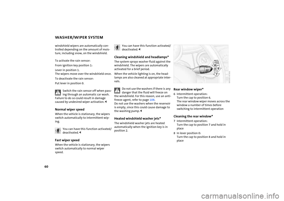
Rear window wiper * 6 Intermittent operation:
Turn the cap to position
6.
The rear window wiper moves across the
window a number of times before
switching to interm ittent operationCleaning the rear window * 7 Intermittent operation:
Turn the cap to position
7 and hold in
place
8 In lever position
0:
Turn the cap to position
8 and hold in
place
Page 63 of 165

61
OVERVIEW REPAIRS OPERATIONCONTROLS DATA INDEX
CRUISE CONTROL
*
On the multifunction steering wheel
and sports steering wheelAbove approx. 20
mph
/ 30
km/h the cruise
control maintains and stores any desired
speed.
Do not use cruise control on twisting roads, when high traffic density pre
-
vents driving at a constant speed, or when
the road surface does not permit driving at
a constant speed, e.g. due to snow, rain, ice,
or loose surfaces.<
To activate via the multifunction steering wheelFrom ignition key position
1:
Press button
2.
The indicator lamp in the instrument clus
-
ter lights up.
Cruise control is active.To activate via the sports steering
wheel1. Start the engine2. Press button
2.
The indicator lamp in the instrument clus
-
ter lights up.
Cruise control is active.
To deactivate Press button
2 repeatedly until the indica
-
tor lamp goes out.The cruise control is deactivated when the
ignition key is turned to position
0.
The stored speed is cleared.To maintain and store speed or to
acceleratePress button
3.
The system maintains and stores the cur
-
rent vehicle speed. Every time you tap the
button, the speed increases by approx.
1 mph
/ 2
km/h.
Page 65 of 165

63
OVERVIEW REPAIRS OPERATIONCONTROLS DATA INDEX
ODOMETER
CLOCK
FUEL GAUGE
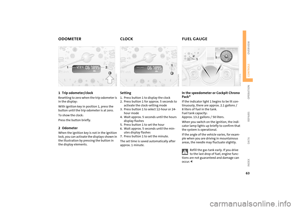
1 Trip odometer/clock
Resetting to zero when the trip odometer is
in the display:With ignition key in position
1, press the
button until the trip odometer is at zero.
To show the clock:Press the button briefly.2 Odometer
When the ignition key is not in the ignition
lock, you can activate the displays shown in
the illustration by pressing the button in
the display elements.
Setting 1. Press button
1 to display the clock
2. Press button
1 for approx. 5
seconds to
activate the clock-setting mode
3. Press button
1 to select 12-hour or 24-
hour mode
4. Wait approx. 5
seconds until the hours
display flashes
5. Press button
1 to set the hour
6. Wait approx. 5
seconds until the min
-
utes display flashes
7. Press button
1 to set the minute.
The set time is saved automatically after
approx. 1
minute.
In the speedometer or Cockpit Chrono Pack* If the indicator light
1 begins to be lit con
-
tinuously, there are approx. 2.1
gallons
/
8
liters of fuel in the tank.
Fuel tank capacity:
Approx. 13.2
gallons
/ 50
liters.
When you switch on the ignition, the indi
-
cator lamp lights up briefly to confirm that
the system is operational. If the angle of the vehicle varies, for exam
-
ple when you are driving in mountainous
areas, the needle may fluctuate slightly.
Refill the gas tank early. If you drive to the last drop of fuel, engine func
-
tions are not guaranteed and damage can
occur.<
Page 67 of 165

65
OVERVIEW REPAIRS OPERATIONCONTROLS DATA INDEX
TACHOMETER
SERVICE INTERVAL DISPLAY
Do not operate the engine with the needle in the red overspeed zone of the gauge.To protect the engine, the power is reduced
when you approach a certain engine speed
in this sector.
Remaining distance for serviceThe distance remaining before the next
scheduled service is displayed in miles
/
kilometers for a short period with the igni
-
tion key in position 1 or higher. The display
also indicates whether an engine oil service
and/or an inspection is due.
The onboard computer bases its calcula
-
tions of the remaining distance on your
driving style in the period immediately pre
-
ceding your data request. The remaining
distance display counts backwards in steps
of 35
miles / 50
km to the next service. A
flashing message and a minus sign in front
of the display that again begins counting
forwards mean that the service interval has
been exceeded.
Please schedule an appointment with your
MINI Dealer or a workshop that has spe
-
cially trained personnel working in accor
-
dance with the specifications of your MINI
manufacturer.For more information on the service inter
-
val display, refer to page
112
.
Page 68 of 165

66
ONBOARD COMPUTER
*
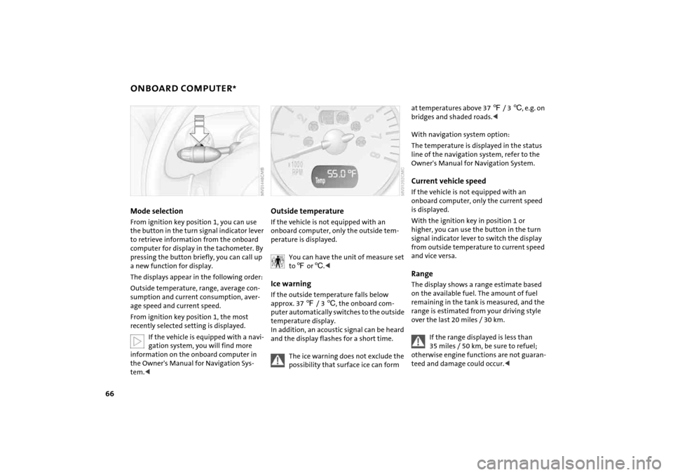
Mode selectionFrom ignition key position
1, you can use
the button in the turn signal indicator lever
to retrieve information from the onboard
computer for display in the tachometer. By
pressing the button briefly, you can call up
a new function for display.
The displays appear in the following order:Outside temperature, range, average con
-
sumption and current consumption, aver
-
age speed and current speed.From ignition key position
1, the most
recently selected setting is displayed.
If the vehicle is equipped with a navi
-
gation system, you will find more
information on the onboard computer in
the Owner's Manual for Navigation Sys
-
tem.<
Outside temperature If the vehicle is not equipped with an
onboard computer, only the outside tem
-
perature is displayed.
You can have the unit of measure set to 7 or
6.<
Ice warning If the outside temperature falls below
approx. 37
7 / 3
6, the onboard com
-
puter automatically switches to the outside
temperature display.
In addition, an acoustic signal can be heard
and the display flashes for a short time.
The ice warning does not exclude the possibility that surface ice can form
at temperatures above 37
7 / 3
6, e.g. on
bridges and shaded roads.<
With navigation system option:The temperature is displayed in the status
line of the navigation system, refer to the
Owner's Manual for Navigation System.Current vehicle speedIf the vehicle is not equipped with an
onboard computer, only the current speed
is displayed.With the ignition key in position
1 or
higher, you can use the button in the turn
signal indicator lever to switch the display
from outside temperature to current speed
and vice versa.
RangeThe display shows a range estimate based
on the available fuel. The amount of fuel
remaining in the tank is measured, and the
range is estimated from your driving style
over the last 20
miles
/ 30 km.
If the range displayed is less than 35 miles
/ 50 km, be sure to refuel;
otherwise engine functions are not guaran
-
teed and damage could occur.<
Page 75 of 165

73
OVERVIEW REPAIRS OPERATIONCONTROLS DATA INDEX
AIRBAGSProtective effectThe front airbags supplement the safety
belts by providing additional protection for
the driver and front passenger in the event
of a frontal collision in which the protec
-
tion afforded by the belts alone may no
longer be sufficient. When needed, the
head and side airbags help to furnish pro
-
tection in the event of side impact. Each of
the side airbags is designed to help support
the seat occupant's upper body. The corre
-
sponding side/head airbag in the MINI Con
-
vertible or the head airbag in the MINI sup
-
ports the head.The airbags are designed to not be trig
-
gered in certain types of collisions, e.g. in
minor accidents, certain kinds of vehicle
rollover and rear impact.For information on the ideal seating posi
-
tion, refer to page
41.
Do not apply adhesive materials to the cover panels of the airbags, cover
them or modify them in any other way. Do
not fit covers, cushions or other items to
the front seats that have not been specially
approved for seats with side airbags. Do
not hang clothing, e.
g. jackets, over the
backrests.
Do not attempt to remove the airbag
restraint system from the vehicle. Do not
touch the individual components directly
after the system has been triggered, as oth
-
erwise there is a danger of burns. In the
event of malfunctions, deactivation or
deployment of the airbag restraint system,
have the system checked, repaired or disas
-
sembled only by a MINI Dealer or a work
-
shop with specially trained personnel work
-
ing in accordance with the specifications of
the MINI manufacturer and having the nec
-
essary permits for handling explosive
devices. Unprofessional attempts to service
the system could lead to failure in an emer
-
gency or undesired airbag activation, either
of which could result in personal injury.
vided on the sun visors.Airbag system operational
The warning lamp in the display elements shows the status of the
entire airbag system and the seat
belt tensioners starting from ignition key
position 1. The warning lamp goes out after
several seconds.
Airbag system malfunctioning >The warning lamp does not come on
starting from ignition key position
1
>The warning lamp stays lit>The warning lamp lights up while driv
-
ing.
In the event of a malfunction, have the airbag system checked immedi
-
ately. Otherwise, there is a risk that the sys
-
tem will not function as intended in
response to a severe impact occurring
within the system's normal triggering
range.<
Page 76 of 165

74
PARK DISTANCE CONTROL (PDC)
*
The conceptThe PDC assists you when you back into a
parking space. A signal tone tells you the
current distance to an object behind your
vehicle. To do this, four ultrasonic sensors
in the rear bumper measure the distance to
the nearest object.
The sensors on each side have a range of
approx. 2
ft / 60
cm, the middle sensors
one of approx. 5 ft / 1.5
m.
PDC is a parking aid that can identify objects if they are approached slowly,
as is generally the case when parking.
Avoid driving towards objects rapidly; due
to underlying physical principles, the sys
-
tem may otherwise alert you too late for
you to take evasive steps.
-
tem starts to operate automatically about
one second after you select reverse gear or
place the selector lever in position R.
Wait for this one second before you drive backwards.<
The system is deactivated when you shift
away from Reverse.
You can have a signal tone set as a confirmation that PDC has been acti
-
vated.
between vehicle and object decreases, the
intervals between the tones become
shorter. A continuous tone indicates the
presence of an object less than 8
in / 20
cm
away.
The warning signal is canceled after
approx. three seconds if the distance to the
object remains constant during this time,
for instance if you are moving parallel to a
wall.MalfunctionA continuous high-pitched tone will sound
during initial activation. The system is mal
-
functioning. Have the system checked.Volume controlThe volume of the Park Distance Control
signal can be adjusted from level
1, soft, to
level
6, loud.You can have this function set.<
System limitations
Even with PDC, final responsibility for estimating the distance between the
vehicle and any objects always remains
with the driver.
Even when sensors are involved, there is a
blind spot in which objects cannot be
detected. Recognition of some objects can
be beyond the limits of physical ultrasonic
measurement, for example with towing
bars or hitches or with thin or wedge-
shaped objects. Moreover, low objects that
have already been detected, such as a curb
edge, can disappear out of the range of the
sensors before a continuous tone sounds.
Loud sources of sound outside and inside
your vehicle can drown the PDC signal
tone.<
Keep the sensors clean and free of ice or snow in order to ensure that they
will continue to operate effectively.
Do not apply high pressure spray to the
sensors for a prolonged period of time.
Always maintain a distance which is
greater than 4
in / 10
cm.<
Page 84 of 165

82
CIGARETTE LIGHTER, 12 V POWER SUPPLY From ignition key position
1:
Press the cigarette lighter in.
Remove as soon as the lighter jumps back
out.
Hold or touch the hot cigarette lighter by the knob only. Holding or
touching it in other areas could result in
burns.<
Cigarette lighter socket, 12 V power
supply Suitable as a power socket for flashlights,
car vacuum cleaners, etc., up to a rating of
approx. 200
watts at 12
volts.
Avoid damaging the socket with plugs of
different shapes or sizes.
When the vehicle is equipped with a MINI
Mobility System, the 12 V socket is also for
supplying the compressor.
12 V socket in the luggage compart
-
ment* of the MINI
Convertible
The socket is located in the luggage com
-
partment on the left-hand side of the rear
panel, arrow.If the vehicle is equipped with a MINI
Mobility System, the 12 V socket is also for
supplying the compressor.
Page 88 of 165

86
LUGGAGE COMPARTMENT IN THE MINI CONVERTIBLE
LOADING CARGO
Loading aidWhen the convertible top is closed, you can
load the vehicle more easily by releasing
the convertible top and folding it up.1. Release the convertible top using the
handles, arrows 12. Lift the convertible top, arrow 23. Fold back the handles and place them on
brackets
3.
Lock the handles in place again com
-
pletely so that the convertible top
can be operated.<
Expanding the luggage compartment volumeYou can enlarge the luggage compartment
volume when the convertible top is closed. 1. Fold the convertible top upwards, refer
to Loading aid2. Remove the luggage compartment cover
from the brackets, arrow 1, and engage
it on the upper support pins, arrow 2.
Move the luggage compartment cover to its lower position again so
that the convertible top can be operated.<
Through-loading system To be able to transport larger objects, the
rear backrest can be folded.1. Unlock the catch for the rear backrest
with an ignition key or master key, refer
to Manual release in the MINI Convert
-
ible on page
30
2. Pull the lever to release the catch3. Fold the backrest forward.
When folding the backrest back into its original position, always ensure
that the catch engages securely. A loose
backrest might fail to prevent cargo from
entering the passenger compartment dur
-
ing sudden braking or evasive maneuvers,
posing a potential hazard to occupants.<