tow MINI Hardtop 2 Door 2005 Owner's Manual
[x] Cancel search | Manufacturer: MINI, Model Year: 2005, Model line: Hardtop 2 Door, Model: MINI Hardtop 2 Door 2005Pages: 165, PDF Size: 2.32 MB
Page 6 of 165
CONTENTS
4
In the engine compartment:Bonnet
105
Engine compartment:
MINI COOPER and
MINI
COOPER
CONVERTIBLE
106
MINI COOPER S and
MINI
COOPER
S CONVERTIBLE
107
Washer fluid
108
Engine oil
108
Coolant
110
Brake fluid
111
Maintenance and care:MINI Maintenance System
112
OBD socket
113
Caring for your vehicle
113
Vehicle storage
116
OWNER SERVICE PROCEDURESReplacement procedures:Onboard tool kit
120
Wiper blades
120
Lamps and bulbs
121
Repairing a flat tire
125
Space-saver spare tire
125
Changing tires
127
MINI Mobility System
129
Battery
132
Fuses
133
Giving and receiving assistance:Jump-starting
134
Towing and tow-starting
136
TECHNICAL DATAEngine data
140
Dimensions:
MINI
141
MINI Convertible
142
Weights:
MINI
143
MINI Convertible
144
Capacities
145
Page 36 of 165
34
GLASS SUNROOF, ELECTRIC
*
ROLLER SUN BLIND
*
Trap protectionIf, while closing, the glass sunroof encoun
-
ters resistance within roughly the last 8
in /
20
cm, the closing procedure is interrupted
and the roof reopens.
Despite the trap protection, be extremely careful that the travel path
of the sunroof is not obstructed whenever
it is closed. Otherwise, it is not guaranteed
that the closing procedure will be inter
-
rupted, for instance if the obstructions
offer very little resistance.
You can disable the trap protection by
pressing the switch past the pressure point
and holding it. When closing the sunroof
from the raised position, ensure that the
travel path of the sunroof is not obstructed
since the trap protection is not active in
this position.
26, for opera
-
tion via the door lock refer to page
27.
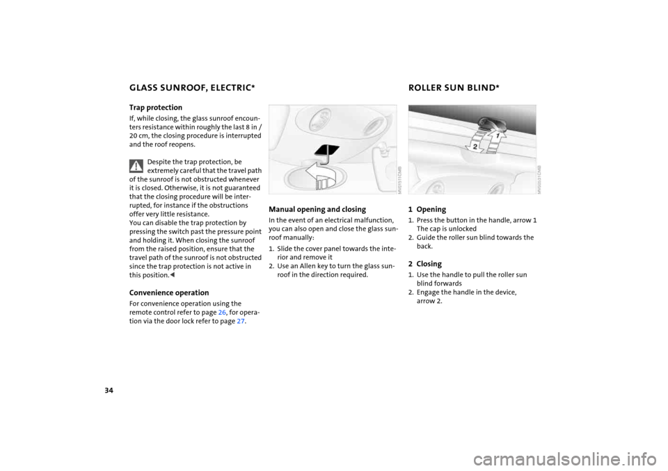
Manual opening and closing In the event of an electrical malfunction,
you can also open and close the glass sun
-
roof manually:1. Slide the cover panel towards the inte
-
rior and remove it
2. Use an Allen key to turn the glass sun
-
roof in the direction required.
1 Opening
1. Press the button in the handle, arrow
1
The cap is unlocked
2. Guide the roller sun blind towards the
back.2 Closing
1. Use the handle to pull the roller sun
blind forwards2. Engage the handle in the device,
arrow
2.
Page 42 of 165
40
WIND DEFLECTOR
*
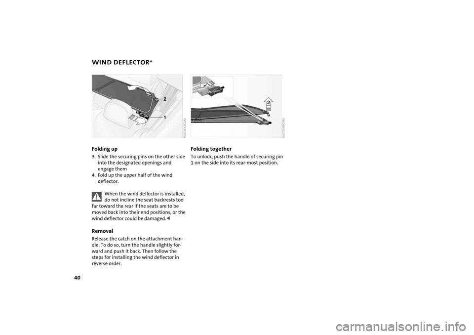
Folding up3. Slide the securing pins on the other side
into the designated openings and
engage them4. Fold up the upper half of the wind
deflector.
When the wind deflector is installed, do not incline the seat backrests too
far toward the rear if the seats are to be
moved back into their end positions, or the
wind deflector could be damaged.<
RemovalRelease the catch on the attachment han
-
dle. To do so, turn the handle slightly for
-
ward and push it back. Then follow the
steps for installing the wind deflector in
reverse order.
Folding togetherTo unlock, push the handle of securing pin
1 on the side into its rear-most position.
Page 44 of 165
42
SEAT ADJUSTMENTImportant adjustment information
Never try to adjust your seat while operating the vehicle. The seat could
respond with an unexpected movement,
and the ensuing loss of vehicle control
could lead to an accident.
While driving, do not recline the backrest
too far toward the rear. This especially
applies to the front passenger side. If you
do so, there is a risk that you will slide
under the safety belt in an accident, thus
reducing the protection provided by the
safety belt.<
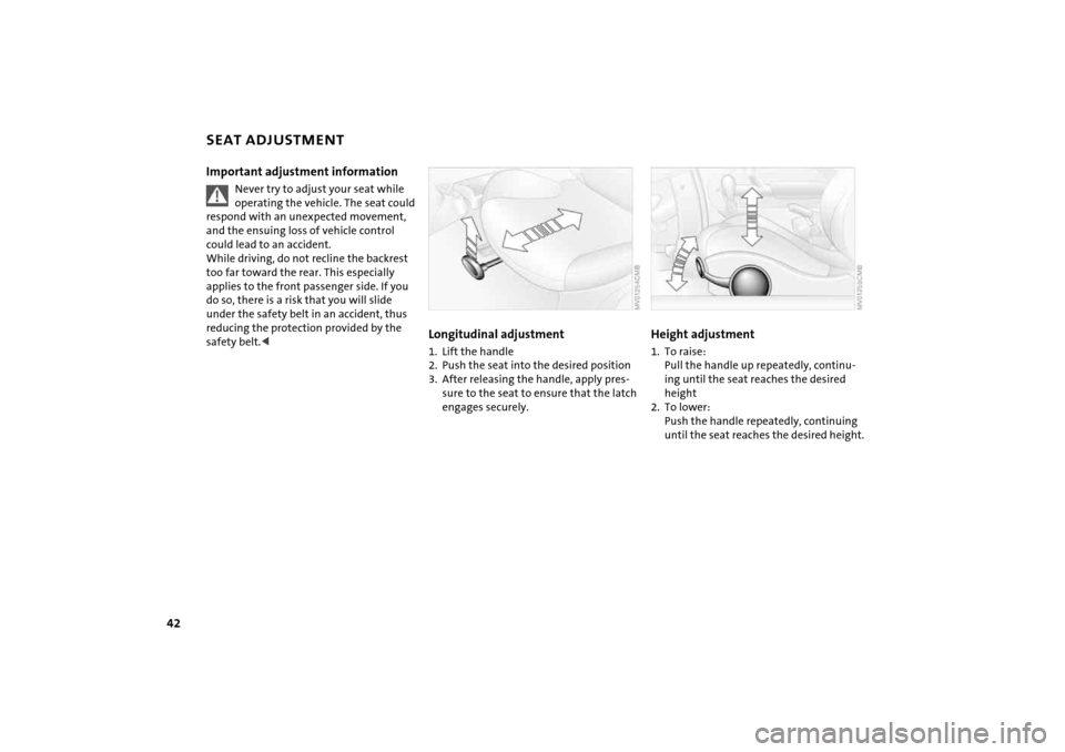
Longitudinal adjustment1. Lift the handle2. Push the seat into the desired position3. After releasing the handle, apply pres
-
sure to the seat to ensure that the latch
engages securely.
Height adjustment 1. To raise:
Pull the handle up repeatedly, continu
-
ing until the seat reaches the desired
height
2. To lower:
Push the handle repeatedly, continuing
until the seat reaches the desired height.
Page 56 of 165
54
MANUAL TRANSMISSION
CONTINUOUSLY VARIABLE AUTOMATIC TRANSMISSION (CVT)
*
Reverse gearBefore selecting reverse gear, ensure the
vehicle is stationary; then, fully depress the
clutch pedal and pause briefly before mov
-
ing the gearshift lever into position.5-speed transmission: Press the gearshift lever to the right and to
the back.6-speed transmission: Press the gearshift lever towards the left.
Thereby overcome the slight resistance and
press forward.As you do this, the backup lamps will come
on automatically when the ignition key is
in position
2.
Do not hold the vehicle in place on slopes by slipping or 'riding' the
clutch. Use the parking brake instead. Oth
-
erwise, a high degree of clutch wear could
result.<
In addition to the fully automatic mode,
you can shift gears manually using Step
-
tronic, refer to page
55.
Selector lever positionsP R N D M/S
+ –
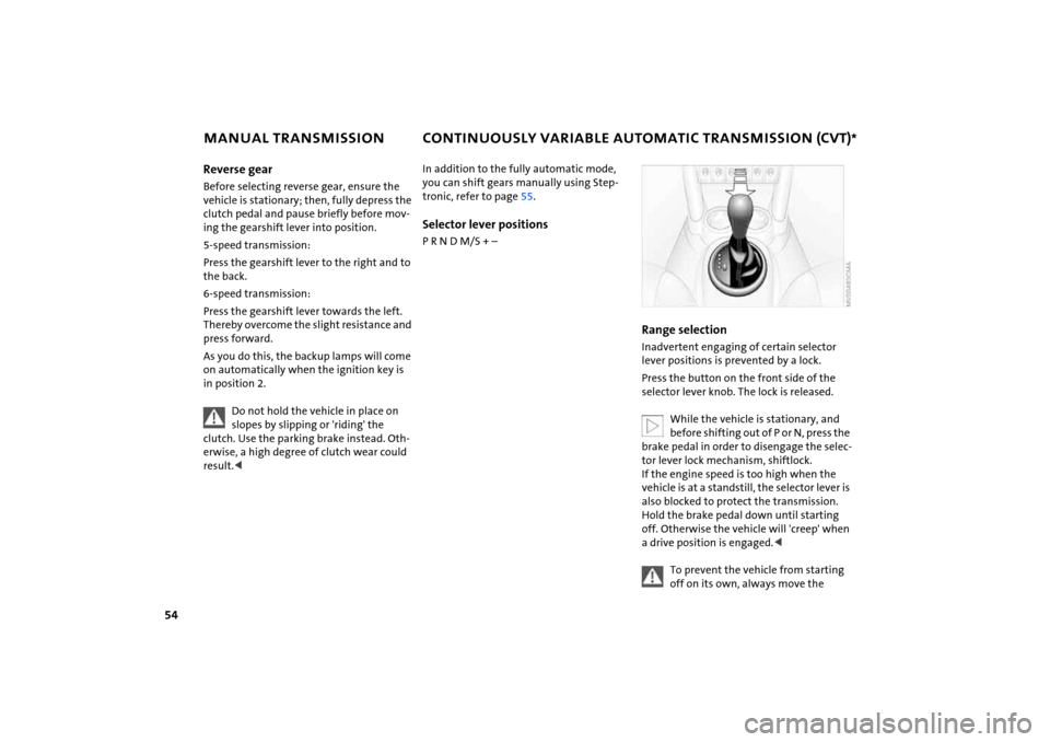
Range selection Inadvertent engaging of certain selector
lever positions is prevented by a lock.Press the button on the front side of the
selector lever knob. The lock is released.
While the vehicle is stationary, and before shifting out of P or N, press the
brake pedal in order to disengage the selec
-
tor lever lock mechanism, shiftlock.
If the engine speed is too high when the
vehicle is at a standstill, the selector lever is
also blocked to protect the transmission.
Hold the brake pedal down until starting
off. Otherwise the vehicle will 'creep' when
a drive position is engaged.<
To prevent the vehicle from starting off on its own, always move the
Page 57 of 165
55
OVERVIEW REPAIRS OPERATIONCONTROLS DATA INDEX
CONTINUOUSLY VARIABLE AUTOMATIC TRANSMISSION (CVT)
*
selector lever to position
P and engage the
parking brake before getting out of your
vehicle with the engine running.
Do not leave the vehicle unattended with
the engine running. This is a safety haz
-
ard.<
If the selector lever is not placed in position
P when the vehicle is parked,
the position display of the selector lever
stays on. This can lead to battery dis
-
charge.<
P Park
Select only when the vehicle is completely
stopped. The transmission locks to prevent
the rear wheels from turning.R Reverse
Select only when the vehicle is completely
stopped.N Neutral Idle
Engage this gear, for example, when you
are in a car wash. The vehicle can roll.D Drive: CVT driving position
This position is designed for driving under
all normal operating conditions. Kickdown Kickdown can be used to achieve maxi
-
mum vehicle performance.
Press the accelerator pedal past the
increased resistance point at the full-throt
-
tle position.
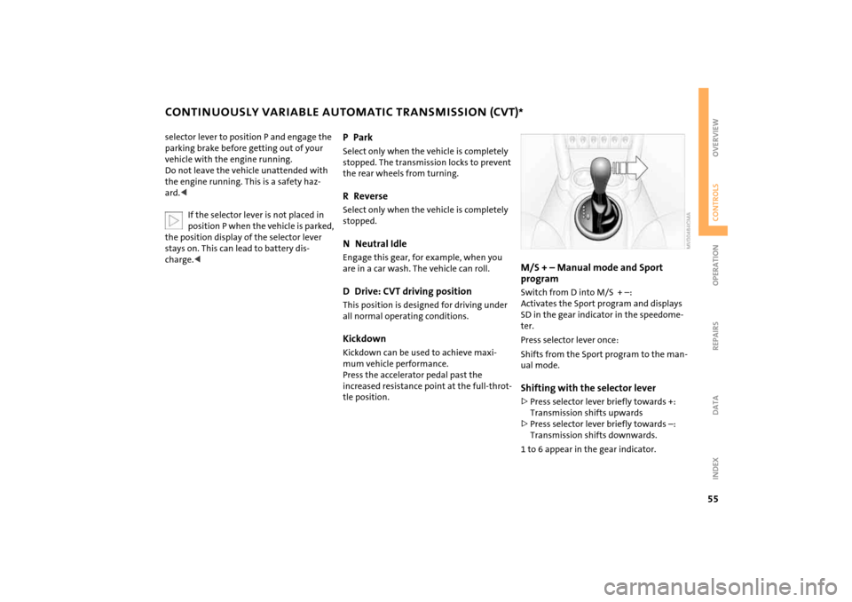
M/S
+ – Manual mode and Sport
program Switch from D into M/S
+ –:
Activates the Sport program and displays
SD in the gear indicator in the speedome
-
ter. Press selector lever once:Shifts from the Sport program to the man
-
ual mode.Shifting with the selector lever>Press selector lever briefly towards +:
Transmission shifts upwards>Press selector lever briefly towards –:
Transmission shifts downwards.1 to 6 appear in the gear indicator.
Page 58 of 165
56
CONTINUOUSLY VARIABLE AUTOMATIC TRANSMISSION (CVT)
*
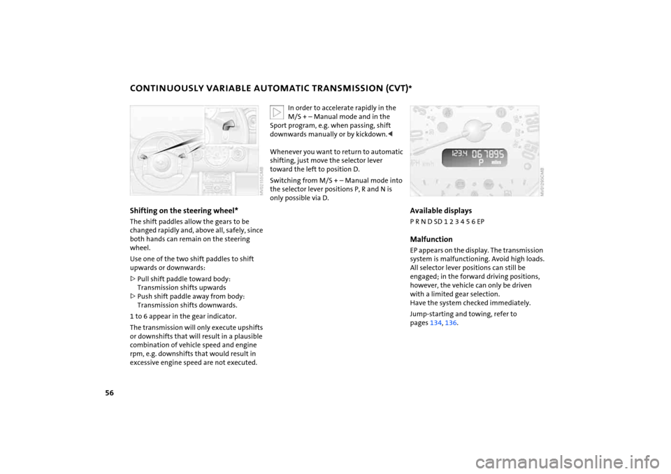
Shifting on the steering wheel* The shift paddles allow the gears to be
changed rapidly and, above all, safely, since
both hands can remain on the steering
wheel.Use one of the two shift paddles to shift
upwards or downwards:>Pull shift paddle toward body:
Transmission shifts upwards>Push shift paddle away from body:
Transmission shifts downwards.1 to 6 appear in the gear indicator.
The transmission will only execute upshifts
or downshifts that will result in a plausible
combination of vehicle speed and engine
rpm, e.g. downshifts that would result in
excessive engine speed are not executed.
In order to accelerate rapidly in the M/S
+ – Manual mode and in the
Sport program, e.g. when passing, shift
downwards manually or by kickdown.<
Whenever you want to return to automatic
shifting, just move the selector lever
toward the left to position D.Switching from M/S
+ – Manual mode into
the selector lever positions P, R and N is
only possible via D.
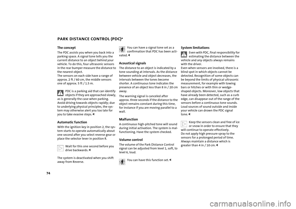
Available displaysP R N D SD 1 2 3 4 5 6 EPMalfunctionEP appears on the display. The transmission
system is malfunctioning. Avoid high loads.
All selector lever positions can still be
engaged; in the forward driving positions,
however, the vehicle can only be driven
with a limited gear selection.
Have the system checked immediately.Jump-starting and towing, refer to
pages
134
, 136
.
Page 76 of 165
74
PARK DISTANCE CONTROL (PDC)
*
The conceptThe PDC assists you when you back into a
parking space. A signal tone tells you the
current distance to an object behind your
vehicle. To do this, four ultrasonic sensors
in the rear bumper measure the distance to
the nearest object.
The sensors on each side have a range of
approx. 2
ft / 60
cm, the middle sensors
one of approx. 5 ft / 1.5
m.
PDC is a parking aid that can identify objects if they are approached slowly,
as is generally the case when parking.
Avoid driving towards objects rapidly; due
to underlying physical principles, the sys
-
tem may otherwise alert you too late for
you to take evasive steps.
-
tem starts to operate automatically about
one second after you select reverse gear or
place the selector lever in position R.
Wait for this one second before you drive backwards.<
The system is deactivated when you shift
away from Reverse.
You can have a signal tone set as a confirmation that PDC has been acti
-
vated.
between vehicle and object decreases, the
intervals between the tones become
shorter. A continuous tone indicates the
presence of an object less than 8
in / 20
cm
away.
The warning signal is canceled after
approx. three seconds if the distance to the
object remains constant during this time,
for instance if you are moving parallel to a
wall.MalfunctionA continuous high-pitched tone will sound
during initial activation. The system is mal
-
functioning. Have the system checked.Volume controlThe volume of the Park Distance Control
signal can be adjusted from level
1, soft, to
level
6, loud.You can have this function set.<
System limitations
Even with PDC, final responsibility for estimating the distance between the
vehicle and any objects always remains
with the driver.
Even when sensors are involved, there is a
blind spot in which objects cannot be
detected. Recognition of some objects can
be beyond the limits of physical ultrasonic
measurement, for example with towing
bars or hitches or with thin or wedge-
shaped objects. Moreover, low objects that
have already been detected, such as a curb
edge, can disappear out of the range of the
sensors before a continuous tone sounds.
Loud sources of sound outside and inside
your vehicle can drown the PDC signal
tone.<
Keep the sensors clean and free of ice or snow in order to ensure that they
will continue to operate effectively.
Do not apply high pressure spray to the
sensors for a prolonged period of time.
Always maintain a distance which is
greater than 4
in / 10
cm.<
Page 82 of 165
80
AUTOMATIC CLIMATE CONTROL
*
Permanent heating with maximum power output at temperature selec
-
tion HI. Permanent cooling at LO. With the
setting at HI, the recirculated air mode can
-
not be switched on.
Indicator lamp lights up.
Ice and condensation are rapidly removed
from the rear window, windshield and side
windows.Condensation is removed from the win
-
dows more quickly when the air condition
-
ing is also activated.
The rear window defroster/windshield
heating are switched on automatically.
They can be switched off again via the
respective button.Individual air distribution
Combine the air distribution your
-
self. Automatic adjustment of the
air distribution is deactivated.
It is not possible to distribute air
simultaneously toward the win
-
dows and toward the upper body area.
You can switch the unit from 7 to 6 by pressing the buttons for air
conditioning and air distribution toward
the footwell at the same time.<
Microfilter/Activated-charcoal filterThe microfilter removes dust and pollen
from the incoming or recirculated air. The
activated-charcoal filter provides addi
-
tional protection by filtering gaseous pol
-
lutants from the outside air.
Your MINI Dealer replaces this combined
filter as a standard part of your scheduled
maintenance. A substantial reduction in
the air supply indicates that the filter must
be replaced before scheduled maintenance.
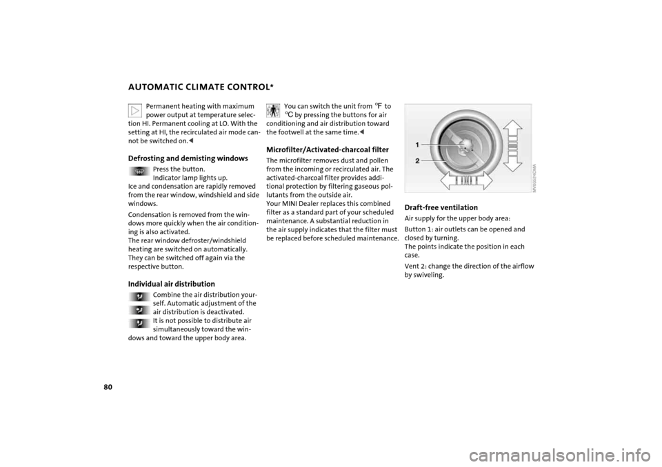
Draft-free ventilation Air supply for the upper body area:Button
1: air outlets can be opened and
closed by turning.
The points indicate the position in each
case.Vent
2: change the direction of the airflow
by swiveling.
Page 87 of 165
85
OVERVIEW REPAIRS OPERATIONCONTROLS DATA INDEX
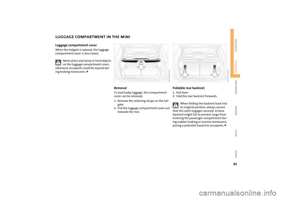
LUGGAGE COMPARTMENT IN THE MINILuggage compartment cover When the tailgate is opened, the luggage
compartment cover is also raised.
Never place any heavy or hard objects on the luggage compartment cover;
otherwise occupants could be injured dur
-
ing braking maneuvers.<
RemovalTo load bulky luggage, the compartment
cover can be removed. 1. Remove the retaining straps on the tail
-
gate
2. Pull the luggage compartment cover out
towards the rear.
Foldable rear backrest 1. Pull lever2. Fold the rear backrest forwards.
When folding the backrest back into its original position, always ensure
that the catch engages securely. A loose
backrest might fail to prevent cargo from
entering the passenger compartment dur
-
ing sudden braking or evasive maneuvers,
posing a potential hazard to occupants.<