warning lights MINI Hardtop 2 Door 2005 Owner's Manual
[x] Cancel search | Manufacturer: MINI, Model Year: 2005, Model line: Hardtop 2 Door, Model: MINI Hardtop 2 Door 2005Pages: 165, PDF Size: 2.32 MB
Page 18 of 165
16
INDICATOR AND WARNING LAMPS Technology that monitors itselfThe system runs a check on the indicator
and warning lamps marked by
+ each time
you switch on the ignition. They each light
up once for different periods of time.
If a malfunction should occur in one of
these systems, the corresponding lamp
does not go out after the engine is started
or it lights up while the vehicle is moving.
You will see below the correct way to react
to this.
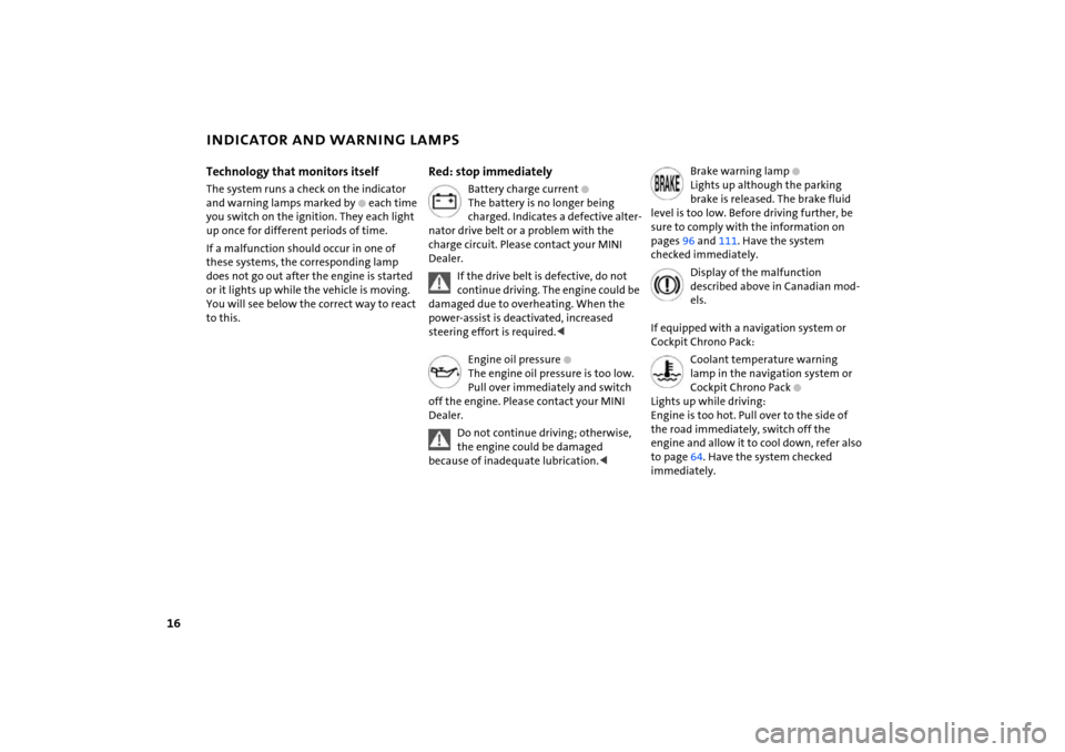
Red: stop immediately
Battery charge current
+
The battery is no longer being
charged. Indicates a defective alter
-
nator drive belt or a problem with the
charge circuit. Please contact your MINI
Dealer.
If the drive belt is defective, do not continue driving. The engine could be
damaged due to overheating. When the
power-assist is deactivated, increased
steering effort is required.
The engine oil pressure is too low.
Pull over immediately and switch
off the engine. Please contact your MINI
Dealer.Do not continue driving; otherwise, the engine could be damaged
because of inadequate lubrication.<
Brake warning lamp
+
Lights up although the parking
brake is released. The brake fluid
level is too low. Before driving further, be
sure to comply with the information on
pages 96 and
111
. Have the system
checked immediately.
Display of the malfunction described above in Canadian mod
-
els.
If equipped with a navigation system or
Cockpit Chrono Pack:
Coolant temperature warning lamp in the navigation system or
Cockpit Chrono Pack
+
Lights up while driving:
Engine is too hot. Pull over to the side of
the road immediately, switch off the
engine and allow it to cool down, refer also
to page
64. Have the system checked
immediately.
Page 19 of 165
17
OVERVIEW REPAIRS OPERATION CONTROLS DATA INDEX
INDICATOR AND WARNING LAMPSYellow: stop immediately
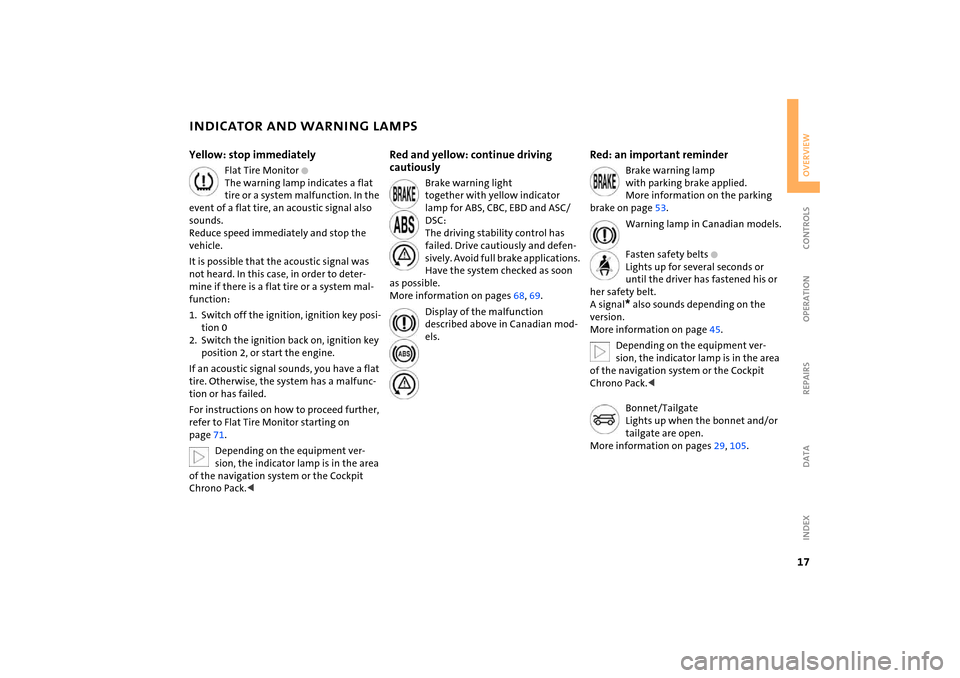
Flat Tire Monitor
+
The warning lamp indicates a flat
tire or a system malfunction. In the
event of a flat tire, an acoustic signal also
sounds.
Reduce speed immediately and stop the
vehicle.It is possible that the acoustic signal was
not heard. In this case, in order to deter
-
mine if there is a flat tire or a system mal
-
function:1. Switch off the ignition, ignition key posi
-
tion 0
2. Switch the ignition back on, ignition key
position 2, or start the engine.If an acoustic signal sounds, you have a flat
tire. Otherwise, the system has a malfunc
-
tion or has failed.For instructions on how to proceed further,
refer to Flat Tire Monitor starting on
page
71.Depending on the equipment ver
-
sion, the indicator lamp is in the area
of the navigation system or the Cockpit
Chrono Pack.<
Red and yellow: continue driving
cautiously
Brake warning light
together with yellow indicator
lamp for ABS, CBC, EBD and ASC/
DSC:
The driving stability control has
failed. Drive cautiously and defen
-
sively. Avoid full brake applications.
Have the system checked as soon
as possible.
More information on pages
68, 69
.
Display of the malfunction described above in Canadian mod
-
els.
Red: an important reminder
Brake warning lamp
with parking brake applied.
More information on the parking
brake on page
53.
Warning lamp in Canadian models.
Fasten safety belts
+
Lights up for several seconds or
until the driver has fastened his or
her safety belt.
A signal
* also sounds depending on the
version.
More information on page
45.
Depending on the equipment ver
-
sion, the indicator lamp is in the area
of the navigation system or the Cockpit
Chrono Pack.
Lights up when the bonnet and/or
tailgate are open.
More information on pages
29, 105
.
Page 21 of 165
19
OVERVIEW REPAIRS OPERATION CONTROLS DATA INDEX
INDICATOR AND WARNING LAMPSYellow: for your information
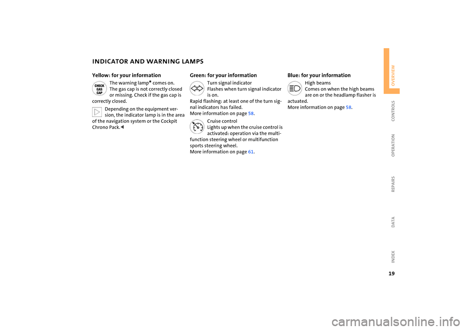
The warning lamp
* comes on.
The gas cap is not correctly closed
or missing. Check if the gas cap is
correctly closed.Depending on the equipment ver
-
sion, the indicator lamp is in the area
of the navigation system or the Cockpit
Chrono Pack.<
Green: for your information
Turn signal indicator
Flashes when turn signal indicator
is on.
Rapid flashing: at least one of the turn sig
-
nal indicators has failed.
More information on page
58.
Cruise control
Lights up when the cruise control is
activated: operation via the multi
-
function steering wheel or multifunction
sports steering wheel.
More information on page
61.
Blue: for your information
High beams
Comes on when the high beams
are on or the headlamp flasher is
actuated.
More information on page
58.
Page 59 of 165

57
OVERVIEW REPAIRS OPERATIONCONTROLS DATA INDEX
PARKING LAMPS/LOW BEAMS Switching on the parking lamps Turn to the first position.
The front, rear and side vehicle lighting is
switched on.
Standing lamps on one side, refer to next
column.Switching on the low beamsTurn to the second position.
With the low beams on and with the igni
-
tion switched off, only the parking lamps
will remain on.
'Follow me home' lampsIf you activate the headlamp flasher after
having switched off the engine and the
lights, the low beams will stay lit for a pre
-
set period of time.
You can have this function pro
-
grammed.<
Switching on the standing lamps For parking, you can activate lights on one
side of the vehicle. Observe local laws.In ignition key position
0:
Move the lever to the adequate turn signal
indicator position.
The standing lamps discharge the battery. Avoid using them for longer
periods of time; otherwise, you may not be
able to start the engine.<
'Lights on' warning If the lights have not been switched off and
the ignition key is in position
0, an acoustic
signal sounds for a few seconds when you
open the driver's door to remind you that
the lights have not been switched off.
Daytime driving lamps* If convenient, the light switch can be left in
position
0 or 1.
The low beams switch on automatically in
ignition key position 2 or higher.
The exterior lamps go out when the igni
-
tion is switched off and the light switch is
set to position 0. In position 1, the parking
lamps are automatically switched on.
The dynamic headlamp range con
-
trol for xenon lamps only operates
with the light switch in position
1 or 2.<
You can have the daytime driving lamp function activated/deacti
-
vated.<
Page 66 of 165
64
FUEL GAUGE
COOLANT TEMPERATURE GAUGE
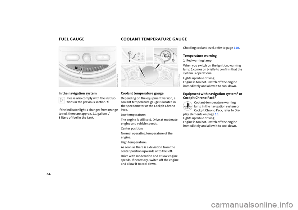
In the navigation system
Please also comply with the instruc
-
tions in the previous section.<
If the indicator light
1 changes from orange
to red, there are approx. 2.1
gallons
/
8
liters of fuel in the tank.
Coolant temperature gaugeDepending on the equipment version, a
coolant temperature gauge is located in
the speedometer or the Cockpit Chrono
Pack.Low temperature:The engine is still cold. Drive at moderate
engine and vehicle speeds.Center position:Normal operating temperature of the
engine.High temperature:As soon as there is a deviation from the
center position upwards or to the left:Drive with moderation and at low engine
speeds. If necessary, switch off the engine
and allow it to cool down.
Checking coolant level, refer to page
110
.
Temperature warning 1 Red warning lampWhen you switch on the ignition, warning
lamp
1 comes on briefly to confirm that the
system is operational.
Lights up while driving:
Engine is too hot. Switch off the engine
immediately and allow it to cool down.Equipment with navigation system* or
Cockpit Chrono Pack*
Coolant-temperature warning lamp in the navigation system or
Cockpit Chrono Pack, refer to Dis
-
play elements on page
15.
Lights up while driving:
Engine is too hot. Switch off the engine
immediately and allow it to cool down.
Page 74 of 165
72
FLAT TIRE MONITOR
AIRBAGS
Do not initialize the system if you are driving with snow chains or a space-
saver spare tire.<
Flat tire
The warning lamp lights up in yel
-
low. An acoustic signal also sounds.
There is a flat tire or a siginificant
loss of pressure in a tire.
1. Reduce speed and stop the vehicle with
caution. Avoid hard brake applications
and steering maneuvers2. Determine which tire is damaged
If this cannot be determined, con
-
tact your MINI Dealer.<
3. Repair the flat tire, refer to page
125
.
With Run Flat tires:1. Reduce vehicle speed carefully to under
50
mph
/ 80 km/h. Avoid hard brake
applications and steering maneuvers. Do
not exceed a speed of 50
mph
/ 80
km/h
2. Check the tire inflation pressure in all
four tires at the earliest opportunity.
If the tire inflation pressure is cor
-
rect in all four tires, it is possible
that the Flat Tire Monitor was not initial
-
ized. In this case, initialize the system.<
3. To continue driving, follow the instruc
-
tions on driving with damaged tires on
page
101
.
Malfunction
The warning lamp lights up in yel
-
low. There is a malfunction in the
Flat Tire Monitor or the system has
failed. Have the system checked as soon as
possible.
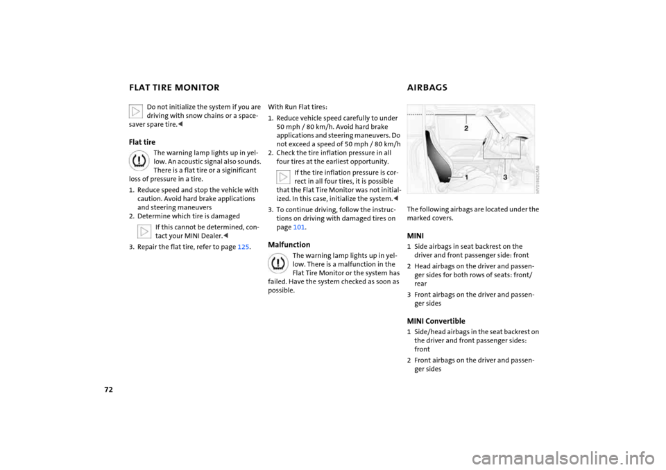
The following airbags are located under the marked covers.MINI 1 Side airbags in seat backrest on the
driver and front passenger side: front2 Head airbags on the driver and passen
-
ger sides for both rows of seats: front/
rear3 Front airbags on the driver and passen
-
ger sidesMINI Convertible1 Side/head airbags in the seat backrest on
the driver and front passenger sides:
front2 Front airbags on the driver and passen
-
ger sides
Page 75 of 165

73
OVERVIEW REPAIRS OPERATIONCONTROLS DATA INDEX
AIRBAGSProtective effectThe front airbags supplement the safety
belts by providing additional protection for
the driver and front passenger in the event
of a frontal collision in which the protec
-
tion afforded by the belts alone may no
longer be sufficient. When needed, the
head and side airbags help to furnish pro
-
tection in the event of side impact. Each of
the side airbags is designed to help support
the seat occupant's upper body. The corre
-
sponding side/head airbag in the MINI Con
-
vertible or the head airbag in the MINI sup
-
ports the head.The airbags are designed to not be trig
-
gered in certain types of collisions, e.g. in
minor accidents, certain kinds of vehicle
rollover and rear impact.For information on the ideal seating posi
-
tion, refer to page
41.
Do not apply adhesive materials to the cover panels of the airbags, cover
them or modify them in any other way. Do
not fit covers, cushions or other items to
the front seats that have not been specially
approved for seats with side airbags. Do
not hang clothing, e.
g. jackets, over the
backrests.
Do not attempt to remove the airbag
restraint system from the vehicle. Do not
touch the individual components directly
after the system has been triggered, as oth
-
erwise there is a danger of burns. In the
event of malfunctions, deactivation or
deployment of the airbag restraint system,
have the system checked, repaired or disas
-
sembled only by a MINI Dealer or a work
-
shop with specially trained personnel work
-
ing in accordance with the specifications of
the MINI manufacturer and having the nec
-
essary permits for handling explosive
devices. Unprofessional attempts to service
the system could lead to failure in an emer
-
gency or undesired airbag activation, either
of which could result in personal injury.
vided on the sun visors.Airbag system operational
The warning lamp in the display elements shows the status of the
entire airbag system and the seat
belt tensioners starting from ignition key
position 1. The warning lamp goes out after
several seconds.
Airbag system malfunctioning >The warning lamp does not come on
starting from ignition key position
1
>The warning lamp stays lit>The warning lamp lights up while driv
-
ing.
In the event of a malfunction, have the airbag system checked immedi
-
ately. Otherwise, there is a risk that the sys
-
tem will not function as intended in
response to a severe impact occurring
within the system's normal triggering
range.<
Page 98 of 165
96
BRAKE SYSTEMBrake fluid levelIf the brake fluid level is too low and brake
pedal travel has become longer, there may
be a defect in one of the brake system's
hydraulic circuits.
Proceed to the nearest MINI Dealer. Higher brake application pressure
may be necessary under these conditions,
there may be a slight pull to one side, and
brake pedal travel may be longer. Please
remember to adapt your driving style
accordingly.<
Disc brakesWhen the vehicle is driven only occasion
-
ally, during extended periods when the
vehicle is not used at all, and in operating
conditions where brake applications are
less frequent, there is an increased ten
-
dency for corrosion of the brake rotors and
accumulation of contamination on the
brake pads. This occurs because the mini
-
mal pressure that must be exerted by the
pads to clean the rotors by brake applica
-
tions is not reached. Corrosion on brake rotors is signaled by a
running or pulsation during braking; even
extended subsequent braking will not cure
this phenomenon.
It is a good idea to periodically dry the
brakes with a gentle application when driv
-
ing in rain and on wet roads.
Monitor traffic conditions to ensure that
this maneuver does not endanger other
road users. The resulting heat dries the
brake rotors and pads. Then if the braking
force is needed, it is immediately available.Driving downhill
To prevent overheating and the resulting reduced efficiency of the
brake system, drive down extended or
steep mountain gradients in the gear
which requires the least brake applications.
Otherwise, even light but consistent pedal
pressure can lead to high temperatures,
brake wear and possibly even brake fail
-
ure.
ther utilized by downshifting, to first gear if
necessary, in the manual mode of the auto
-
matic transmission, refer to page
55. This
protects the brakes from excessive loads.
Do not coast with the clutch pedal pressed or with the transmission or
selector lever in Neutral. Do not coast with
the engine switched off. The engine pro
-
vides no braking effect when the transmis
-
sion is in Neutral, and there is no power-
assist for braking or steering when the
engine is switched off.
Make sure that there are no floor mats,
floor carpets or other objects in the vicinity
of the brake or accelerator pedal, as the
travel path of the pedals could otherwise
be impeded.
the rear axle monitor the brake pad condi
-
tion. When the brake pads reach the wear
limit, the brake wear warning lights up,
refer to page
18.
Use brake pads which the manufac
-
turer of your MINI has approved for
your particular vehicle model. The manu
-
facturer of your MINI cannot evaluate non-
approved brake pads to determine if they
are suitable for use, and therefore cannot
ensure the operating safety of the vehicle
in the event of their use.<
Page 155 of 165
EVERYTHING FROM A TO Z
153
OVERVIEW REPAIRS OPERATION CONTROLS DATA INDEX
Interlock, refer to Steering
locked
51
Intermittent operation of the
wipers
59
Interval
display, service
112
J Jack
125
, 129
points
128
Jack, refer to Tire change set
MINI Mobility System
129
Run Flat tires
102
space-saver spare tire
125
Jacking points
128
Jets, refer to Ventilation
77, 80
Jets, refer to Windshield
washer jets
60
Jump-starting
134
K Keys
24
Kickdown
55
Knock control
94
L Lamp defect
121
Lamp replacement, refer to
Lamps and bulbs
121
Lamps and bulbs
121
Lamps, refer to Parking lamps/
Low beams
57
Lashing eyelets, refer to
Securing the load
88
LATCH child-restraint
mounting system
50
Leather care
115
LEDs light-emitting diodes
124
Length, refer to
Dimensions
141
, 142
License plate lamp, bulb
replacement
124
Lifting handle, space-saver
spare tire
125
Light switch
57
Light-alloy wheels, care
114
Light-emitting diodes
(LEDs)
124
Lighter
82
Lighting of the instruments
58
'Lights on' warning
57
Load securing devices, refer to
Securing the load
88
Loading the vehicle
86
Loads, refer to Loading cargo
86
Locking
from inside
28
from outside
26
Locking/unlocking the vehicle,
acknowledgment
signals
26, 27
Low beams
57
bulb replacement
122
Lower back support, refer to
Lumbar support
43
Luggage compartment
cover
85
emergency operation, refer
to Manual release
30
opening from the outside
29
opening with the remote
control
26
opening/closing, refer to
Tailgate
29
tailgate
29
volume
143
, 144
Luggage compartment in the
MINI
85
Luggage compartment lid
emergency operation, refer
to Manual release
30
opening, remote control
26
Luggage compartment lid, refer
to Tailgate
29
Luggage compartment net
88
Luggage rack, refer to Roof-
mounted luggage rack
89
Lumbar support
43
M M+S tires, refer to Winter
tires
103
Maintenance system
112
Make-up mirror, illuminated
47
Malfunction
Continuously Variable
automatic Transmission
(CVT)
56
convertible top
37
door lock
27
fuel filler door
95
glass sunroof, electric
34
tailgate
30
Manual air distribution
76
Manual operation
door lock
27
driver's door
27
fuel filler door
95
glass sunroof, electric
34
power convertible top
37
tailgate
30
transmission lock for
Continuously Variable
automatic Transmission
(CVT)
54
Manual transmission
53
Master keys with remote
control
24
Maximum cooling
79
Maximum speed, with winter
tires
103
MC operation, refer to
Owner's Manual for Radio