engine MINI Hardtop 2 Door 2006 User Guide
[x] Cancel search | Manufacturer: MINI, Model Year: 2006, Model line: Hardtop 2 Door, Model: MINI Hardtop 2 Door 2006Pages: 168, PDF Size: 2.22 MB
Page 56 of 168

54
STARTING THE ENGINE SWITCHING OFF THE ENGINE PARKING BRAKE
Manual transmission
1. Engage the parking brake
2. Gearshift lever in idle position
3. Depress the clutch
4. Start the engine.
Automatic transmission with
Steptronic
1. Press the footbrake
2. Put the selector lever in position P or N
3. Start the engine.
Special starting conditions
In the following situations, depress the
accelerator pedal halfway and continue
starting the engine for up to approx.
10 seconds:
>If the engine does not start on the first
attempt, for instance if the engine is very
hot or cold.
>The engine is started at very low temper-
atures, below approx. +57/–156, at
high altitudes above 3,300 ft/1000 m.You should never remove the ignition
key when the vehicle is in motion, as
the steering lock could engage.
When you leave the vehicle, always remove
the ignition key and engage the steering
lock.
When parking on inclines, engage the park-
ing brake, or the vehicle could roll.<
Manual transmission
Turn the ignition key to position 1 or 0.
Automatic transmission with
Steptronic
Engage selector lever position P, turn the
ignition key to position 1 or 0.
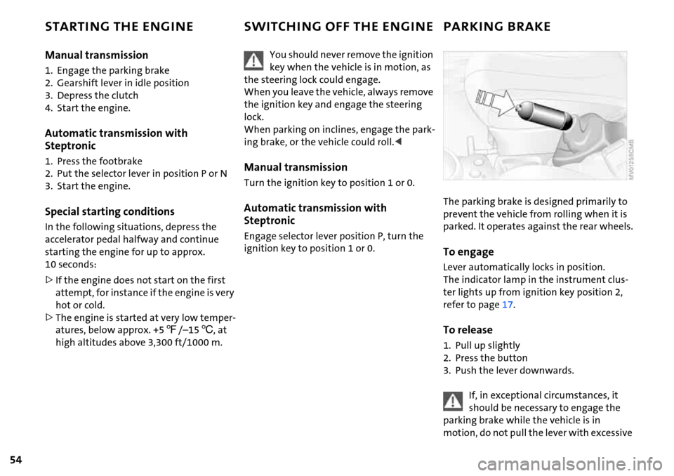
The parking brake is designed primarily to
prevent the vehicle from rolling when it is
parked. It operates against the rear wheels.
To engage
Lever automatically locks in position.
The indicator lamp in the instrument clus-
ter lights up from ignition key position 2,
refer to page17.
To release
1. Pull up slightly
2. Press the button
3. Push the lever downwards.
If, in exceptional circumstances, it
should be necessary to engage the
parking brake while the vehicle is in
motion, do not pull the lever with excessive
Page 57 of 168

55
OVERVIEW REPAIRS OPERATIONCONTROLS DATA INDEX
PARKING BRAKE MANUAL TRANSMISSION
force. Keep your thumb pressed against the
release button while pulling the lever up
carefully.
Otherwise, excessive force could lead to
overbraking and loss of traction, i.e. fish-
tailing, at the rear axle.<
To avoid corrosion and one-sided
braking, apply the parking brake
lightly from time to time when coasting to
a standstill, for instance at a traffic light,
provided that it is safe to do so. The brake
lamps do not come on when the parking
brake is engaged.<
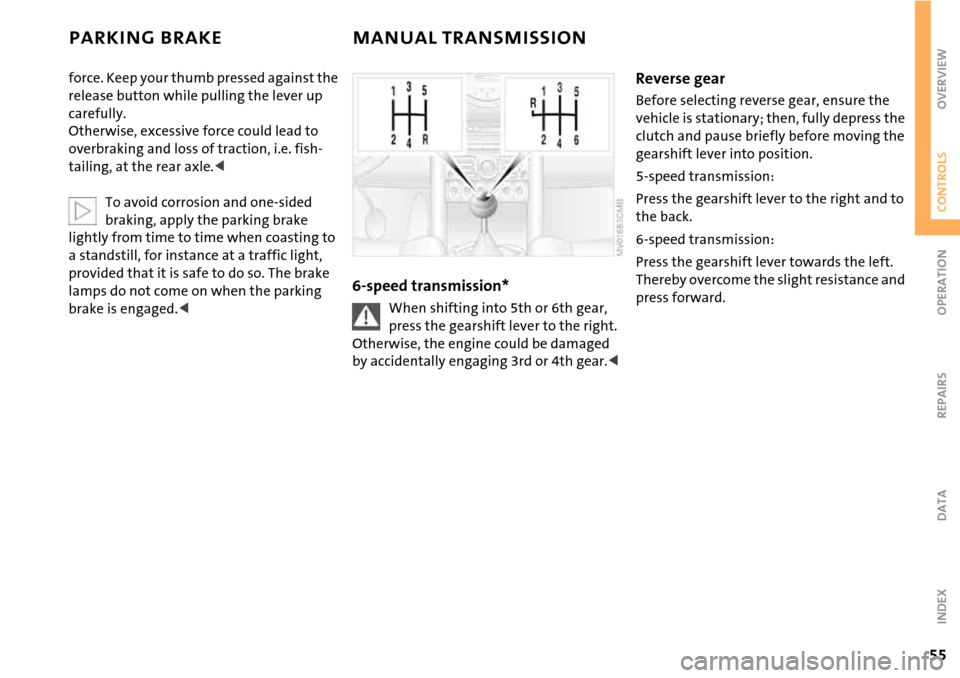
6-speed transmission*
When shifting into 5th or 6th gear,
press the gearshift lever to the right.
Otherwise, the engine could be damaged
by accidentally engaging 3rd or 4th gear.<
Reverse gear
Before selecting reverse gear, ensure the
vehicle is stationary; then, fully depress the
clutch and pause briefly before moving the
gearshift lever into position.
5-speed transmission:
Press the gearshift lever to the right and to
the back.
6-speed transmission:
Press the gearshift lever towards the left.
Thereby overcome the slight resistance and
press forward.
Page 58 of 168

56
AUTOMATIC TRANSMISSION WITH STEPTRONIC*
In addition to the fully automatic mode,
you can shift gears manually using Step-
tronic, refer to page57.
Selector lever positions
P R N D M/S + –
Range selection
>The selector lever can be moved out of
position P when the ignition is switched
on or the engine is running: interlock.
>While the vehicle is stationary and
before shifting out of P or N, depress the
footbrake in order to disengage the
selector lever's lock mechanism: shift-
lock.
Keep your foot on the brake until start-
ing off, otherwise the vehicle will start
to move when a drive position is
engaged.
A lock prevents the selector lever from
being inadvertently moved into the R and P
positions. To override the lock, press the
button on the front of the selector lever
knob, see arrow.
If the engine speed is too high when
the vehicle is at a standstill, the selec-
tor lever is also blocked to protect the
transmission.
If the selector lever is not placed in
position P when the vehicle is parked, the
position display of the selector lever stays
on. This can lead to battery discharge.<
PPark
Select only when the vehicle is completely
stopped. The transmission locks to prevent
the drive wheels from turning.
RReverse
Select only when the vehicle is completely
stopped.
NNeutral, idle
Select this when you are in a car wash, for
example. The vehicle can roll.
D Drive: automatic driving position
This position is designed for driving under
all normal operating conditions.
Under normal operation conditions, fuel
consumption is lowest when you drive in
position D.
Page 60 of 168

58
AUTOMATIC TRANSMISSION WITH STEPTRONIC*
Switching from M/S + – Manual mode into
the selector lever positions P, R and N is
only possible via D.
Shifting with the selector lever
>Press selector lever briefly towards +:
Transmission shifts upwards
>Press selector lever briefly towards –:
Transmission shifts downwards.
M1 to M6 appear in the gear indicator.
Shifting on the steering wheel*
The shift paddles allow the gears to be
changed rapidly and, above all, safely, since
both hands can remain on the steering
wheel.
To shift up or down with one of the two
shift paddles:
>Pull the shift paddle:
Transmission shifts up
>Press the shift paddle:
Transmission shifts down.
M1 to M6 appear in the gear indicator.
The transmission will only execute upshifts
or downshifts that will result in a plausible
combination of vehicle speed and engine
rpm, e.g. downshifts that would result in
excessive engine speed are not executed.
In the MINI COOPER S, with the selec-
tor lever in position D, automatic
mode, you can shift gears using the shift
paddles on the steering wheel. The trans-
mission automatically switches to manual
mode. If you do not shift gears with the
shift paddles or accelerate for a certain
amount of time, the transmission auto-
matically returns to automatic mode.<
Malfunction
EP appears on the display. The transmission
system is malfunctioning. Avoid high loads.
All selector lever positions can still be
engaged; in the forward driving positions,
however, the vehicle can only be driven
with a limited gear selection.
Have the system checked immediately.
Jump-starting and towing, refer to
page140 ff.
Page 61 of 168

59
OVERVIEW REPAIRS OPERATIONCONTROLS DATA INDEX
PARKING LAMPS/LOW BEAMS
1 Parking lamps
2 Low beams
3 Automatic headlamp control
*
Parking lamps
Turn the light switch to position 1.
The front, rear and side vehicle
lighting is switched on.
For the additional option of activating the
lights on one side of the vehicle for parking,
refer to Switching on the standing lamps,
page59.
The parking lamps discharge the bat-
tery.
Avoid using them for longer periods of
time; otherwise, you may not be able to
start the engine.<
Low beams
Turn the light switch to position 2.
With the low beams on and with
the ignition switched off, only the
parking lamps will remain on.
Automatic headlamp control*
In switch position 3, the system
automatically activates and can-
cels the low beams in response to
changes in ambient light, for example in
tunnels, at dusk, and when there is precipi-
tation.
When driving into a tunnel with bright
overhead lights, there may be a delay
before the low beams come on.
The low beams may also come on when the
sun is sitting low on a blue sky.
When you switch on the fog lamps,
the low-beam headlamps remain on
regardless of the ambient light. When the
daytime driving lamps are activated, refer
to page60, the low beams come on and
remain lit when the switch is in position 1
and the ignition is switched on.<
Automatic headlamp control cannot
serve as a substitute for the driver's
judgement in determining when the vehi-
cle lights should be switched on. For exam-
ple, the sensors are not able to detect fog.
To avoid safety risks, you should respond to
these kinds of low-visibility situations by
switching the headlamps on manually.<
You can have the sensitivity of your
vehicle's automatic headlamp con-
trol adjusted.<
Pathway lighting
If you activate the headlamp flasher after
having switched off the engine and the
lights, the low beams will stay lit for a pre-
set period of time.
You can have this function pro-
grammed.<
Switching on the standing lamps
For parking, you can activate lights on one
side of the vehicle. Observe local laws.
In ignition key position 0:
Move the lever to the adequate turn signal
indicator position.
The standing lamps discharge the
battery. Avoid using them for longer
periods of time; otherwise, you may not be
able to start the engine.<
Page 66 of 168

64
WASHER FLUID CRUISE CONTROL*
Washer fluid level
The yellow LED in the wiper control lever
lights up when the washer fluid level is too
low.
In the following situations, the LED flashes
for approx. 10 seconds when the washer
fluid level has dropped to a minimum:
>When cleaning the windshield and head-
lamps by pulling the wiper control lever
>When the ignition is switched on
>When starting the engine
On the multifunction sports steering
wheel
Above approx. 20 mph / 30 km/h the cruise
control maintains and stores any desired
speed.
Do not use cruise control when unfa-
vorable conditions make it inadvis-
able to drive at a constant speed. Other-
wise, the vehicle could go out of control
and an accident could be caused. Unfavor-
able conditions include, for example, twist-
ing roads, high traffic density, or adverse
road conditions such as snow, rain, ice, or
loose surfaces.<
To activate via the multifunction
sports steering wheel
1. Starting the engine
2. Press button 2.
The indicator lamp in the instrument clus-
ter lights up.
Cruise control is active.
Page 67 of 168

65
OVERVIEW REPAIRS OPERATIONCONTROLS DATA INDEX
CRUISE CONTROL*
To deactivate
Press button 2 repeatedly until the indica-
tor lamp goes out.
The cruise control is deactivated when the
ignition key is turned to position 0.
The stored speed is cleared.
To maintain, store and increase speed
Press button 3.
The system maintains and stores the cur-
rent vehicle speed. Every time you tap the
button, the speed increases by approx.
1mph/ 2km/h.
Press and hold button 3.
The vehicle accelerates without pressure
on the accelerator pedal. When you release
the button, the system maintains and
stores the current speed.
If, on a downhill grade, the engine
braking effect is not sufficient, the
controlled speed can be exceeded. Speed
can drop on uphill grades if the engine out-
put is insufficient.<
To maintain, store and decrease speed
Press button 4.
If you are already driving with active cruise
control, the speed is decreased by approx.
1 mph / 2 km/h every time you tap the but-
ton.
Press and hold button 4.
With the cruise control active, the system
automatically reduces the throttle opening
to slow the vehicle. When you release the
button, the system maintains and stores
the current speed.
To cancel the cruise control
The cruise control is automatically can-
celed:
>When the brakes are applied
>When the clutch is depressed
>If the cruising speed is either exceeded or
not met for an extended length of time,
for example if you press the accelerator
pedal and exceed the stored speed
>When ASC or DSC is in action.
The indicator lamp stays lit.
You can use the cruise control again as
required.
On the multifunction steering wheel, the
cruise control can be interrupted manually:
When the system is activated, press
button 2.
To continue cruise control
Press button 1.
The vehicle accelerates to and maintains
the last speed stored.
Page 68 of 168

66
ODOMETER CLOCK FUEL GAUGE
1 Trip odometer/clock
2Odometer
Trip odometer/clock
To switch between the trip odometer and
the clock:
Press the button.
To reset the trip odometer to zero:
Press the button until the trip odometer
shows zero.
To set the clock, refer to the information
below.
Odometer
When the ignition key is not in the ignition
lock, you can activate the displays shown in
the illustration by pressing the button in
the display elements.
Setting
The clock must be shown on the display.
1. If necessary, press button 1 to display
the clock
2. Press button 1 for approx. 5 seconds to
activate the clock-setting mode
3. Press button 1 to select 12-hour or
24-hour mode
4. Wait approx. 5 seconds until the hours
display is shown
5. Press button 1 to set the hour
6. Wait approx. 5 seconds until the min-
utes display is shown
7. Press button 1 to set the minute.
The time entered is stored automatically
after approx. 1 minute.
In the speedometer or Cockpit Chrono
Pack*
If the LED begins to be lit continuously,
there are approx. 2.1 gallons/8 liters of fuel
left in the tank.
Fuel tank capacity:
Approx. 13.2 gallons/50 liters.
When you switch on the ignition, the LED
lights up briefly to confirm that the system
is operational.
If the angle of the vehicle varies, for exam-
ple when you are driving in mountainous
areas, the needle may fluctuate slightly.
Refill the gas tank early. If you drive
to the last drop of fuel, engine func-
tions are not guaranteed and damage can
occur.<
Page 69 of 168

67
OVERVIEW REPAIRS OPERATIONCONTROLS DATA INDEX
FUEL GAUGE COOLANT TEMPERATURE GAUGE
In the navigation system*
Please also comply with the instruc-
tions in the previous section.<
If the LED changes from orange to red,
there are approx. 2.1 gallons/8 liters of fuel
left in the tank.
Coolant temperature gauge
Depending on the equipment version, a
coolant temperature gauge is located in
the speedometer or the Cockpit Chrono
Pack.
Low temperature:
The engine is still cold. Drive at moderate
engine and vehicle speeds.
Center position:
Normal operating temperature of the
engine.
High temperature:
As soon as there is a deviation from the
center position upwards or to the left:
Drive with moderation and at low engine
speeds. If necessary, switch off the engine
and allow it to cool down.
Checking coolant level, refer to page115.
Temperature warning
LED 1 lights up while driving:
Engine is too hot. Switch off the engine
immediately and allow it to cool down.
When you switch on the ignition, the LED 1
lights up briefly to confirm that the system
is operational.
Equipment with navigation system* or
Cockpit Chrono Pack*
Coolant-temperature warning
lamp 2 lights up while driving:
Engine is too hot. Switch off the
engine immediately and allow it to cool
down.
Page 70 of 168

68
TACHOMETER SERVICE INTERVAL DISPLAY
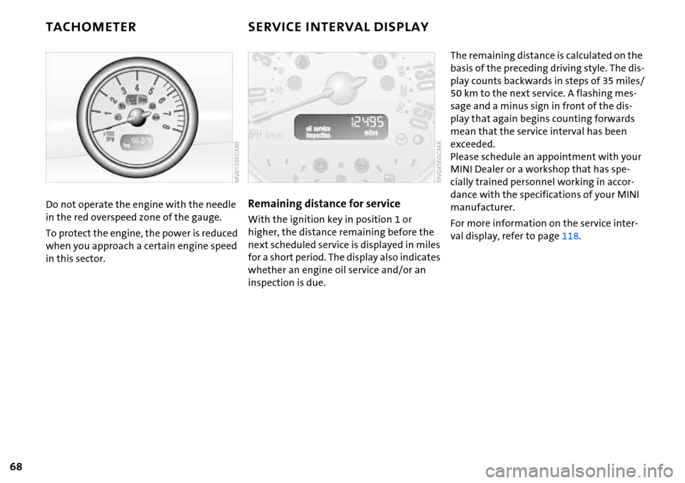
Do not operate the engine with the needle
in the red overspeed zone of the gauge.
To protect the engine, the power is reduced
when you approach a certain engine speed
in this sector.Remaining distance for service
With the ignition key in position 1 or
higher, the distance remaining before the
next scheduled service is displayed in miles
for a short period. The display also indicates
whether an engine oil service and/or an
inspection is due.
The remaining distance is calculated on the
basis of the preceding driving style. The dis-
play counts backwards in steps of 35 miles/
50 km to the next service. A flashing mes-
sage and a minus sign in front of the dis-
play that again begins counting forwards
mean that the service interval has been
exceeded.
Please schedule an appointment with your
MINI Dealer or a workshop that has spe-
cially trained personnel working in accor-
dance with the specifications of your MINI
manufacturer.
For more information on the service inter-
val display, refer to page118.