light MINI Hardtop 2 Door 2006 Owner's Guide
[x] Cancel search | Manufacturer: MINI, Model Year: 2006, Model line: Hardtop 2 Door, Model: MINI Hardtop 2 Door 2006Pages: 168, PDF Size: 2.22 MB
Page 76 of 168
74
FLAT TIRE MONITOR
Flat tire warning
The warning lamp lights up in yel-
low. An acoustic signal also sounds.
There is a flat tire or a significant
loss of pressure in a tire.
1. Reduce speed and stop the vehicle with
caution. Avoid hard brake applications
and steering maneuvers.
2. Determine which tire is damaged.
If this cannot be determined, con-
tact your MINI Dealer.<
3. Repair the flat tire, refer to page131.
Vehicles with Run Flat tires:
1. Reduce vehicle speed carefully to under
50 mph / 80 km/h. Avoid hard brake
applications and steering maneuvers. Do
not exceed a speed of 50 mph /
80 km/h.
Do not continue driving if the vehi-
cle is not equipped with Run Flat
tires, refer to page108. If you continue
to drive with a flat tire, a serious acci-
dent could result.<
2. Check the tire inflation pressure in all
four tires at the earliest opportunity.
If the tire inflation pressure is cor-
rect in all four tires, it is possible
that the Flat Tire Monitor was not initial-
ized. In this case, initialize the system.<
3. If there is a total loss of tire inflation
pressure, 0 psi/0 kPa, or obvious tire
damage, you can gauge the mileage for
continued driving on the basis of the fol-
lowing indications:
>With a light load:
1 to 2 persons without luggage:
approx. 155 miles/250 km
>With a medium load:
2 persons, full luggage compartment, or
4 persons without luggage:
approx. 90 miles/150 km
>With a full load:
4 persons or more, full luggage compart-
ment:
approx. 30 miles/50 km.
Drive cautiously. Do not exceed a
speed of 50 mph / 80 km/h. In case of
tire pressure loss you must expect changes
in vehicle handling such as lower track sta-
bility during braking, longer braking dis-
tances and changes in self-steering proper-
ties when close to the handling limit.
For safety reasons, the manufacturer of
your MINI recommends not having dam-
aged Run Flat tires repaired, but to consult
a MINI Dealer in such cases.
low. There is a malfunction in the
Flat Tire Monitor or the system has
failed. Have the system checked as soon as
possible.
Page 78 of 168
76
AIRBAGS
tivated or activated, refer to Functional sta-
tus of the front passenger airbags below. <
Before transporting a child on the
front passenger seat, read the safety
notes and instructions under Transporting
children safely, refer to page50.
Adolescents and adults sitting in certain
positions could also deactivate the front
and side airbags for the front passenger;
the indicator lamp for the front passenger
airbags comes on. In such cases, the occu-
pant should change his or her sitting posi-
tion so that the front passenger airbags are
activated and the indicator lamp goes out.
If the airbags are not activated although
the seat occupant has changed his or her
position, have the occupant sit on a rear
seat. Do not attach covers, cushions, ball
mats or other items to the front passenger
seat unless they are specifically recom-
mended by the manufacturer of your MINI.
Do not place any objects under the seat
which could press against the seat from
below. Otherwise, a correct analysis of the
seat cushion is not ensured.<
Functional status of the front
passenger airbags
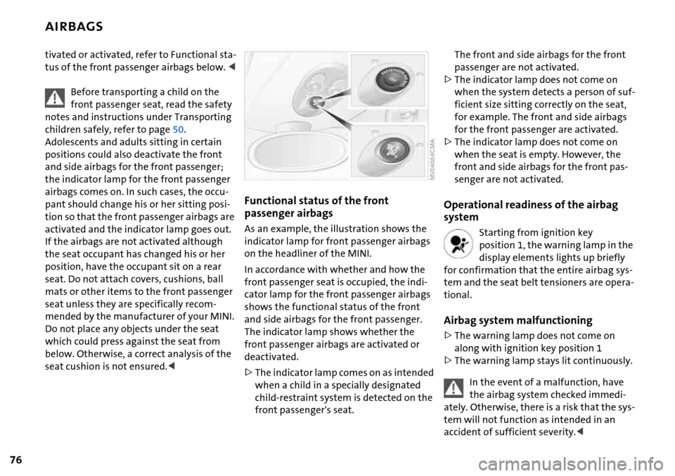
As an example, the illustration shows the
indicator lamp for front passenger airbags
on the headliner of the MINI.
In accordance with whether and how the
front passenger seat is occupied, the indi-
cator lamp for the front passenger airbags
shows the functional status of the front
and side airbags for the front passenger.
The indicator lamp shows whether the
front passenger airbags are activated or
deactivated.
>The indicator lamp comes on as intended
when a child in a specially designated
child-restraint system is detected on the
front passenger's seat.
The front and side airbags for the front
passenger are not activated.
>The indicator lamp does not come on
when the system detects a person of suf-
ficient size sitting correctly on the seat,
for example. The front and side airbags
for the front passenger are activated.
>The indicator lamp does not come on
when the seat is empty. However, the
front and side airbags for the front pas-
senger are not activated.
Operational readiness of the airbag
system
Starting from ignition key
position 1, the warning lamp in the
display elements lights up briefly
for confirmation that the entire airbag sys-
tem and the seat belt tensioners are opera-
tional.
Airbag system malfunctioning
>The warning lamp does not come on
along with ignition key position 1
>The warning lamp stays lit continuously.
In the event of a malfunction, have
the airbag system checked immedi-
ately. Otherwise, there is a risk that the sys-
tem will not function as intended in an
accident of sufficient severity.<
Page 86 of 168

84
GLOVE COMPARTMENT CENTER ARMREST*
To open
Pull the handle.
The light goes on.
To close
Fold the door up.
To prevent injury in the event of an
accident, close the glove compart-
ment immediately after use.<
Ventilation
To allow ventilation:
Turn the rotary switch to the horizontal
position.
To stop ventilation:
Turn the rotary switch to the vertical posi-
tion, see arrow.
Depending on the temperature set-
ting of the air conditioning or the
automatic climate control, high tempera-
tures may result in the glove compart-
ment.<
Storage compartments
Depending on the equipment version*, the
center armrest between the front seats
contains a compartment or a base plate for
a mobile phone.
To open:
Slide the cover backwards.
The cover slides along guide rails and
can be opened fully by pushing it
back and lifting it slightly.<
To close:
Push the cover forwards.
Page 87 of 168

85
OVERVIEW REPAIRS OPERATIONCONTROLS DATA INDEX
DRINKS HOLDERS, ASHTRAY CIGARETTE LIGHTER, 12 V POWER SUPPLY
Beverage holders
Beverage holders are at the front or top of
the center console. Another is located at
the end of the center console in the rear.
Do not place any glass containers in
the beverage holders, as this
increases the risk of injury in the event of
an accident.<
Ashtray
The ashtray is located in one of the bever-
age holders in the center console.
Lighter
Press the cigarette lighter in.
Remove as soon as the lighter jumps back
out.
Hold or touch the hot cigarette lighter
by the knob only. Holding or touching
it in other areas could result in burns.<
Cigarette lighter socket, 12 V power
supply
Suitable as a power socket for flashlights,
car vacuum cleaners, etc., up to a rating of
approx. 200 watts at 12 volts.
Avoid damaging the socket with plugs of
different shapes or sizes.
If the vehicle is equipped with a MINI
Mobility System, the 12 V socket is also for
supplying the compressor.
12 V socket in the luggage
compartment* of the MINI Convertible
The socket is located in the luggage com-
partment on the left-hand side of the rear
panel, arrow.
Page 94 of 168

92
LOADING CARGO
Stowing cargo
>Place heavy cargo as far forward as possi-
ble, directly behind the backrests, and as
low as possible
>Cover sharp edges and corners
>Do not pile objects higher than the top
edges of the backrests.
For very heavy cargo when the rear seat is
unoccupied, fasten each safety belt in the
opposite buckle. This provides additional
stabilization for the backrests.Securing the load
As an example, the illustration shows the
luggage compartment of the MINI.
>Secure smaller and lighter items using
the luggage compartment net
* or elas-
tic straps
>Secure larger and heavier items with
load-securing devices
*. Lashing eyelets
are provided at the inner corners of the
luggage compartment for attaching
these load-securing devices.
Comply with the information enclosed
with the load-securing devices.
Page 98 of 168
96
BREAK-IN PROCEDURES GENERAL DRIVING NOTES
Moving parts need to be given some time
until they can interact smoothly with one
another. To ensure that your vehicle pro-
vides maximum economy throughout a
long service life, we request that you com-
ply with the following information:
Engine
Comply with the local speed limits.
Up to 1,250 miles/2,000 km:
Drive at varying engine and road speeds,
but do not exceed the following:
4,500 rpm or
95 mph / 150 km/h.
Absolutely avoid putting the accelerator in
full-throttle or kickdown position.
After 1,250 miles/2,000 km:
Engine and road speeds can be gradually
increased.
Tires
Due to technical factors associated with
their manufacture, tires do not achieve
their full traction potential until after an
initial break-in period. Therefore drive care-
fully during the first 200 miles/300 km.
Brake system
Approx. 300 miles/500 km must be driven
before the brake pads and rotors achieve
the optimum pad-surface and wear pat-
terns required for trouble-free operation
and an extended service life.
Clutch
Roughly 300 miles/500 km must be driven
before the clutch starts to operate at opti-
mum efficiency. Remember to engage the
clutch carefully during this initial period.
After a part replacement
You should again comply with these break-
in procedures if parts mentioned above
have to be replaced later in the vehicle's
life.
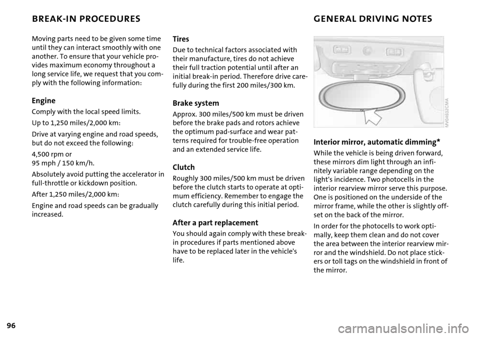
Interior mirror, automatic dimming*
While the vehicle is being driven forward,
these mirrors dim light through an infi-
nitely variable range depending on the
light's incidence. Two photocells in the
interior rearview mirror serve this purpose.
One is positioned on the underside of the
mirror frame, while the other is slightly off-
set on the back of the mirror.
In order for the photocells to work opti-
mally, keep them clean and do not cover
the area between the interior rearview mir-
ror and the windshield. Do not place stick-
ers or toll tags on the windshield in front of
the mirror.
Page 99 of 168
97
OVERVIEW REPAIRSOPERATIONCONTROLS DATA INDEX
GENERAL DRIVING NOTES
Safe braking
Your vehicle is equipped with ABS as a stan-
dard feature. If you are in a situation which
requires full braking, it is best to brake
using maximum brake pressure. Since the
vehicle remains maneuverable, you can still
go around any obstacles with the smallest
possible steering movements.
The pulsation of the brake pedal, together
with the sound of hydraulic regulation,
indicates to you that ABS is actively taking
effect.
Wet roads:
It is a good idea to periodically dry the
brakes with a gentle application when driv-
ing in rain and on wet roads. Monitor traffic
conditions to ensure that this maneuver
does not hinder other road users. The
resulting heat dries brake rotors and pads.
Then if the braking force is needed, it is
immediately available.
Driving downhill:
To prevent overheating and the
resulting reduced efficiency of the
brake system, drive down extended or
steep mountain gradients in the gear
which requires the least brake applications.
Otherwise, even light but consistent pres-
sure on the brake can lead to high tempera-
tures, brake wear and possibly even brake
failure.<
The braking effect of the engine can be
increased by downshifting in the manual
mode of the automatic transmission, to
first gear if necessary, refer to page58. This
protects the brakes from excessive loads.
Do not coast with the clutch
depressed, the transmission in idle or
the engine switched off. Otherwise, the
engine provides no braking effect, and
there is no power-assist for braking or
steering.
Make sure that there are no floor mats,
floor carpets or other objects in the vicinity
of the pedals; otherwise pedal function
could be impeded.<
Corrosion on the brake rotors:
When the vehicle is driven only occasion-
ally, during extended periods when the
vehicle is not used at all, and in operating
conditions where brake applications are
less frequent, there is an increased ten-
dency for corrosion of the brake rotors and
accumulation of contamination on the
brake pads. This occurs because the mini-
mal pressure that must be exerted by the pads to clean the rotors by brake applica-
tions is not reached.
Corrosion on brake rotors is signaled by a
running or pulsation during braking; even
extended subsequent braking will not cure
this phenomenon.
Hydroplaning
When driving on wet or slushy roads,
reduce road speed. If you do not, a
wedge of water can form between tires
and road surface. This phenomenon is char-
acterized by a partial or complete loss of
contact between the tires and the road sur-
face. The ultimate results are loss of steer-
ing and braking control.<
Page 112 of 168
110
NEW WHEELS AND TIRES SNOW CHAINS*
Special characteristics of winter tires
The manufacturer of your MINI recom-
mends winter tires for driving in adverse
winter road conditions. While all-season
tires with the M+S designation provide bet-
ter winter traction than summer tires, they
generally do not achieve the full perfor-
mance of winter tires.
Observe speed ratings:
Never exceed the maximum speed
for which the winter tires are rated.<
Storage
Store tires in a cool, dry place, protecting
them against light whenever possible. Pro-
tect the tires against contact with oil,
grease and fuel. Do not exceed the tire
inflation pressure specified on the tire side-
wall.
Only certain types of snow chains have
been tested by the manufacturer of your
MINI, classified as road-safe and recom-
mended. Contact your MINI Dealer for
more details. Their use is only permitted in
pairs on the front wheels on winter tires of
the following types:
>175/65 R 15 M+S
>175/60 R 16 M+S.
When fitting, comply with the manufac-
turer's instructions. With chains, do not
exceed a speed of 30 mph / 50 km/h.
Do not initialize the Flat Tire Monitor
after attaching snow chains to the
tires.
When driving with snow chains, it can be
helpful to switch off the ASC or DSC for a
brief period, refer to page71.<
Page 118 of 168

116
COOLANT
As an example, the illustration shows the
coolant tank of the MINI COOPER and the
MINI COOPER Convertible.
Checking coolant level
1. The engine must be at ambient temper-
ature
2. MINI COOPER and MINI COOPER Con-
vertible:
Slowly pull the cap of the expansion
tank by the tab until the excess pressure
can escape. Then remove the cap com-
pletely.
MINI COOPER S and MINI COOPER S Con-
vertible:
Loosen the cap of the expansion tank
slightly by turning it counterclockwise
until the excess pressure can escape.
Then remove the cap completely
3. The coolant level is correct if it is
between the MIN and MAX markings on
the transparent expansion tank
4. If necessary, slowly add coolant until the
correct level is reached; do not overfill
5. MINI COOPER and MINI COOPER Con-
vertible:
Press the cap on and press it down
firmly.
MINI COOPER S and MINI COOPER S Con-
vertible:
Turn the cap back on and tighten it
firmly
6. Have the cause of the coolant loss
removed as soon as possible.
Page 119 of 168
117
OVERVIEW REPAIRSOPERATIONCONTROLS DATA INDEX
BRAKE SYSTEM
Brake fluid level
The warning lamp comes on
although the parking brake is
released:
The brake fluid level in the reservoir is too
low, refer to page16. At the same time,
brake pedal travel may become signifi-
cantly longer.
Have the system checked immediately.
If the brake fluid level is too low and brake
pedal travel has become longer, there may
be a defect in one of the brake system's
hydraulic circuits.
Display of the malfunction
described above in Canadian mod-
els.
If you continue driving, higher brake
application pressure may be neces-
sary, and there may be a slight pull to one
side. Brake pedal travel may also be longer.
Please remember to adapt your driving
style accordingly.<
Brake pads
Brake pad sensors in the left brake pads of
the front axle and in the right brake pads of
the rear axle monitor the brake pad condi-
tion. When the brake pads reach the wear
limit, the brake wear warning lights up,
refer to page18.
Use brake pads which the manufac-
turer of your MINI has approved for
your particular vehicle model. The manu-
facturer of your MINI cannot evaluate non-
approved brake pads to determine if they
are suitable for use, and therefore cannot
ensure the operating safety of the vehicle
in the event of their use.<