ESP MINI Hardtop 2 Door 2010 (Mini Connected) User Guide
[x] Cancel search | Manufacturer: MINI, Model Year: 2010, Model line: Hardtop 2 Door, Model: MINI Hardtop 2 Door 2010Pages: 230, PDF Size: 4.02 MB
Page 65 of 230

MOBILITYAT A GLANCE CONTROLS DRIVING TIPS ENTERTAINMENT
63
NAVIGATION REFERENCE
3.If necessary, move the highlight marker to
the uppermost field. Select "Car Data".
4.Select "Onboard info".
>Estimated time of arrival at destination:
>Manually enter a distance in the com-
puter, refer to information further below
>Enter a destination in the navigation sys-
tem, page114
>Cruising range
>Distance to destination:
>Manually enter a distance in the com-
puter, refer to information further below
>Enter a destination in the navigation sys-
tem, page114
>Average speed
>Average fuel consumption
Resetting values
To reset the values for the average speed and
average fuel consumption:
1.Select the respective menu entry.
2.Press the MINI joystick to confirm the
message.
Entering a distance manually
1.Select "Dist. to dest.".
2.Turn the MINI joystick to select the distance
to your destination.
3.Press the MINI joystick to apply the setting.
The distance is mandated automatically during
destination guidance.
Trip computer
The trip computer is suitable e.g. for a
holiday trip.
1.Press the button.
This opens the start menu.
2.Move the MINI joystick to highlight "Naviga-
tion" and press the MINI joystick.
3.Select "Car Data".
4.Select "Trip computer".
>Departure time
>Driving time
>Distance traveled
>Average speed
>Average fuel consumption
To switch trip computer on/off and to reset all
values to zero:
Page 73 of 230

MOBILITYAT A GLANCE CONTROLS DRIVING TIPS ENTERTAINMENT
71
NAVIGATION REFERENCE
For most Check Control messages, you can view
more information later, e.g. regarding the cause
of a malfunction and how to respond, refer to
page72.
In urgent cases, this information will be shown
as soon as the corresponding lamp comes on.
To exit the displayed information:
Select the arrow.
Hiding Check Control messages
Press the button in the turn indicator lever.
Some Check Control messages are displayed
until the malfunctions have been rectified. They
cannot be hidden. If several malfunctions occur
at the same time, they are displayed in suc-
cession.They are marked with the symbol shown
here.
Other Check Control messages are automatically
hidden after approx. 20 seconds, but remain
stored.
They are marked with the symbol
shown here.
This symbol indicates that Check Control
messages have been stored. Check Control mes-
sages can be viewed whenever it is convenient.
Viewing stored Check Control messages
Stored Check Control messages can only be dis-
played if the driver's door is closed.
1.Briefly press the button in the turn indicator
lever repeatedly until "SET/INFO" is dis-
played.
2.Press and hold the button until the display
changes.
Page 74 of 230

Controls overview
72
3.Press the button repeatedly until the display
shows the corresponding symbol and
"CHECK INFO".
4.Hold the button down.
"CHECK OK" appears if there are no Check
Control messages.
If a Check Control message has been stored,
the corresponding message is displayed. In
addition, the text message appears on the
Control Display.
5.Briefly press the button to check for other
messages.
Viewing more information later
Onboard monitor, for operating principle refer
to page16.
1.Press the button.
This opens the start menu.
2.Move the MINI joystick to highlight "Setup"
and press the MINI joystick.
3.Select "Info sources".
4.Select "Service Info".5.If necessary, move the highlight marker to
the uppermost field. Select "Check Control
messages".
6.Select a text message.
Exit display:
Select the arrow.
Speed limit
Enter a speed, and a Check Control message will
indicate when you reach this speed. This enables
you, for example, to receive warnings if you
exceed a speed limit in an urban area.
You are only warned of reaching this speed a
second time if your vehicle speed falls below it
again by at least 3 mph or 5 km/h.
Displaying, setting or changing the limit
Onboard monitor, for operating principle refer
to page16.
1.Press the button.
This opens the start menu.
2.Move the MINI joystick to highlight "Naviga-
tion" and press the MINI joystick.
3.Select "Car Data".
Page 78 of 230
Technology for driving comfort and safety
76
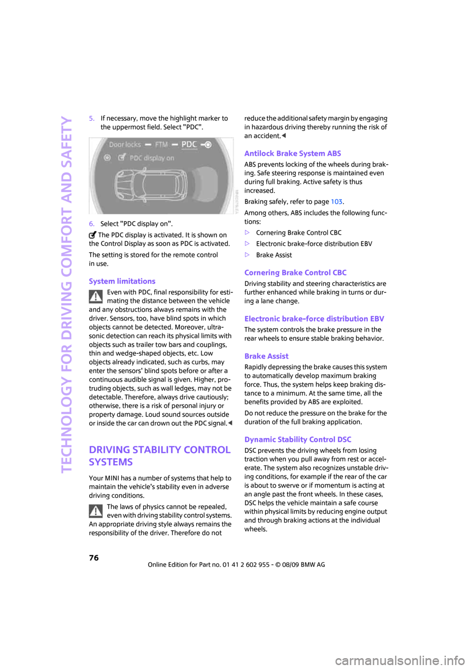
5.If necessary, move the highlight marker to
the uppermost field. Select "PDC".
6.Select "PDC display on".
The PDC display is activated. It is shown on
the Control Display as soon as PDC is activated.
The setting is stored for the remote control
in use.
System limitations
Even with PDC, final responsibility for esti-
mating the distance between the vehicle
and any obstructions always remains with the
driver. Sensors, too, have blind spots in which
objects cannot be detected. Moreover, ultra-
sonic detection can reach its physical limits with
objects such as trailer tow bars and couplings,
thin and wedge-shaped objects, etc. Low
objects already indicated, such as curbs, may
enter the sensors' blind spots before or after a
continuous audible signal is given. Higher, pro-
truding objects, such as wall ledges, may not be
detectable. Therefore, always drive cautiously;
otherwise, there is a risk of personal injury or
property damage. Loud sound sources outside
or inside the car can drown out the PDC signal.<
Driving stability control
systems
Your MINI has a number of systems that help to
maintain the vehicle's stability even in adverse
driving conditions.
The laws of physics cannot be repealed,
even with driving stability control systems.
An appropriate driving style always remains the
responsibility of the driver. Therefore do not reduce the additional safety margin by engaging
in hazardous driving thereby running the risk of
an accident.<
Antilock Brake System ABS
ABS prevents locking of the wheels during brak-
ing. Safe steering response is maintained even
during full braking. Active safety is thus
increased.
Braking safely, refer to page103.
Among others, ABS includes the following func-
tions:
>Cornering Brake Control CBC
>Electronic brake-force distribution EBV
>Brake Assist
Cornering Brake Control CBC
Driving stability and steering characteristics are
further enhanced while braking in turns or dur-
ing a lane change.
Electronic brake-force distribution EBV
The system controls the brake pressure in the
rear wheels to ensure stable braking behavior.
Brake Assist
Rapidly depressing the brake causes this system
to automatically develop maximum braking
force. Thus, the system helps keep braking dis-
tance to a minimum. At the same time, all the
benefits provided by ABS are exploited.
Do not reduce the pressure on the brake for the
duration of the full braking application.
Dynamic Stability Control DSC
DSC prevents the driving wheels from losing
traction when you pull away from rest or accel-
erate. The system also recognizes unstable driv-
ing conditions, for example if the rear of the car
is about to swerve or if momentum is acting at
an angle past the front wheels. In these cases,
DSC helps the vehicle maintain a safe course
within physical limits by reducing engine output
and through braking actions at the individual
wheels.
Page 80 of 230
Technology for driving comfort and safety
78
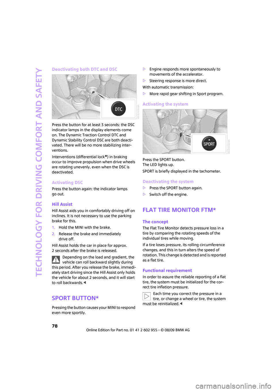
Deactivating both DTC and DSC
Press the button for at least 3 seconds: the DSC
indicator lamps in the display elements come
on. The Dynamic Traction Control DTC and
Dynamic Stability Control DSC are both deacti-
vated. There will be no more stabilizing inter-
ventions.
Interventions (differential lock
*) in braking
occur to improve propulsion when drive wheels
are rotating unevenly, even when the DSC is
deactivated.
Activating DSC
Press the button again: the indicator lamps
go out.
Hill Assist
Hill Assist aids you in comfortably driving off on
inclines. It is not necessary to use the parking
brake for this.
1.Hold the MINI with the brake.
2.Release the brake and immediately
drive off.
Hill Assist holds the car in place for approx.
2 seconds after the brake is released.
Depending on the load and gradient, the
vehicle can roll backward slightly during
this period. After you release the brake, immedi-
ately start driving since the Hill Assist only holds
the vehicle for about 2 seconds, and it will start
to roll backwards.<
Sport button*
Pressing the button causes your MINI to respond
even more sportily.>Engine responds more spontaneously to
movements of the accelerator.
>Steering response is more direct.
With automatic transmission:
>More rapid gear shifting in Sport program.
Activating the system
Press the SPORT button.
The LED lights up.
SPORT is briefly displayed in the tachometer.
Deactivating the system
>Press the SPORT button again.
>Switch off the engine.
Flat Tire Monitor FTM*
The concept
The Flat Tire Monitor detects pressure loss in a
tire by comparing the rotating speeds of the
individual tires while moving.
If a tire loses pressure, its rolling circumference
changes, and this in turn alters the speed of
rotation. This change is detected and is reported
as a flat tire.
Functional requirement
In order to assure the reliable reporting of a flat
tire, the system must be initialized for the cor-
rect tire inflation pressure.
Each time you correct the pressure in a
tire, or change a wheel or tire, the system
must be reinitialized.<
Page 83 of 230
MOBILITYAT A GLANCE CONTROLS DRIVING TIPS ENTERTAINMENT
81
NAVIGATION REFERENCE
Status indicator on the onboard monitor
The tire and system condition is indicated by the
color of the tires.
TPM takes into account the fact that tire pres-
sure changes while the vehicle is being driven.
The tire pressure does not need to be corrected
unless the TPM instructs you to do so by means
of color indicators.
Green
The tire inflation pressure corresponds to the
established target value.
"TPM active" is displayed on the onboard
monitor.
One wheel yellow
There is a flat tire or substantial loss of tire pres-
sure in the indicated tire. A message appears on
the onboard monitor.
All wheels yellow
There is a flat tire or substantial loss of tire pres-
sure in several tires. A message appears on the
onboard monitor.
Gray
The system cannot detect a puncture.
Possible reasons for this:
>TPM is being reset
>Temporary malfunction caused by systems
or devices using the same radio frequency
>Malfunction
Resetting the system
Each time a tire inflation pressure has
been corrected or a wheel or tire has been
changed, reset the system.<
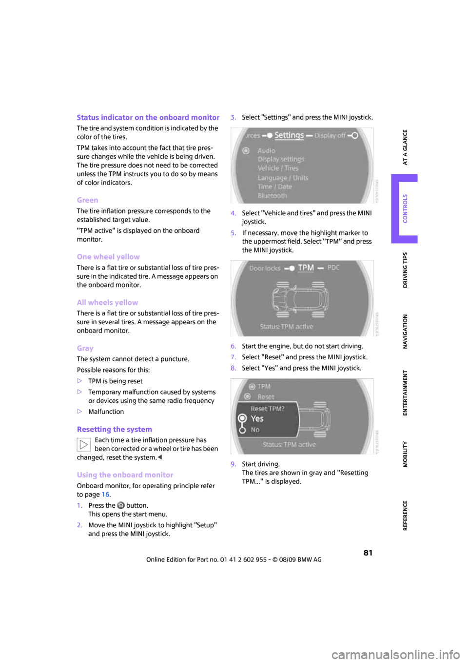
Using the onboard monitor
Onboard monitor, for operating principle refer
to page16.
1.Press the button.
This opens the start menu.
2.Move the MINI joystick to highlight "Setup"
and press the MINI joystick.3.Select "Settings" and press the MINI joystick.
4.Select "Vehicle and tires" and press the MINI
joystick.
5.If necessary, move the highlight marker to
the uppermost field. Select "TPM" and press
the MINI joystick.
6.Start the engine, but do not start driving.
7.Select "Reset" and press the MINI joystick.
8.Select "Yes" and press the MINI joystick.
9.Start driving.
The tires are shown in gray and "Resetting
TPM..." is displayed.
Page 85 of 230
MOBILITYAT A GLANCE CONTROLS DRIVING TIPS ENTERTAINMENT
83
NAVIGATION REFERENCE
Message for unsuccessful system reset
Both warning lamps come on in yellow.
A message appears on the onboard
monitor. The system is not reset after a
tire has been changed, for example.
Check the tire inflation pressure and reset the
system, page81.
Declaration according to NHTSA/
FMVSS 138 Tire Pressure Monitoring
Systems
Each tire, including the spare, should be che-
cked monthly when cold and inflated to the
inflation pressure recommended by the vehicle
manufacturer on the vehicle placard or tire infla-
tion pressure label. If your vehicle has tires of a
different size than the size indicated on the vehi-
cle placard or tire inflation pressure label, you
should determine the proper tire inflation pres-
sure for those tires. As an added safety feature,
your vehicle has been equipped with a tire pres-
sure monitoring system TPMS that illuminates a
low tire pressure telltale when one or more of
your tires are significantly under-inflated.
Accordingly, when the low tire pressure telltale
illuminates, you should stop and check your tires
as soon as possible, and inflate them to the
proper pressure. Driving on a significantly
under-inflated tire causes the tire to overheat
and can lead to tire failure. Underinflation also
reduces fuel efficiency and tire tread life, and
may affect the vehicle's handling and stopping
ability. Please note that the TPMS is not a substi-
tute for proper tire maintenance, and it is the
driver's responsibility to maintain correct tire
pressure, even if underinflation has not reached
the level at which the TPMS low tire pressure tell-
tale illuminates.
The TPMS malfunction indicator is combined
with the low tire pressure telltale. When the sys-
tem detects a malfunction, the telltale will flash
for approximately one minute and then remain
continuously lit. This sequence will continue
upon subsequent vehicle startups as long as the
malfunction exists. When the malfunction indi-
cator is illuminated, the system may not be able
to detect or signal low tire pressure as intended.
TPMS malfunctions may occur for a variety of reasons, including the installation of replace-
ment or alternate tires or wheels on the vehicle
that prevent the TPMS from functioning prop-
erly. Always check the TPMS malfunction telltale
after replacing one or more tires or wheels on
your vehicle to ensure that the replacement or
alternate tires and wheels allow the TPMS to
continue to function properly.
Page 86 of 230

Technology for driving comfort and safety
84
Airbags
The following airbags are located under the
marked covers:
MINI:
1Front airbags
2Side airbags in backrests
3Head airbags at the front and rearMINI Convertible:
1Front airbags
2Side/head airbags in the backrests
Protective effect
Observe the instructions on page42 to
ensure the best possible personal pro-
tection.<
The front airbags help protect the driver and
front passenger by responding to frontal
impacts in which safety belts alone cannot pro-
vide adequate restraint. When needed, the head
and side airbags help provide protection in the
event of side impact. The relevant side airbag
supports the side upper body area. The head air
bag supports the head.
The side/head airbag in the MINI Convertible
protects the head during impact.
The airbags are designed to not be triggered in
every type of collision, e.g. not in minor acci-
dents, certain rollover situations or rear impacts.
Do not apply adhesive materials to the
cover panels of the airbags, cover them or
modify them in any other way.
Keep the dashboard and window on the passen-
ger side free from obstruction, i.e. do not cover it
with adhesive film or coverings, and do not affix
any holders such as for a navigation device or a
mobile phone.
Do not attach seat covers, cushions or other
objects not specifically approved for seats with
integral side airbags to the front seats. Do not hang items of clothing such as coats or jackets
over the backrests. Do not attempt to remove
the airbag retention system from the vehicle. Do
not modify the individual components of the
system or its wiring in any way. This includes the
upholstered covers on the steering wheel,
instrument panel, seats and roof posts, as well as
the sides of the roof lining. Do not attempt to
remove or dismantle the steering wheel.
Do not touch the individual components imme-
diately after the system has been triggered,
because there is a danger of burns.
In the event of malfunctions, deactivation, or
triggering of the airbag restraint system, have
the testing, repair, removal, and disposal of air-
bag generators executed only by a MINI dealer
or a workshop that works according to repair
procedures of the manufacturer of your MINI
with correspondingly trained personnel and has
the required explosives licenses. Otherwise,
unprofessional attempts to service the system
could lead to failure in an emergency or undes-
ired airbag activation, either of which could
result in personal injury.<
Warning notices and information about the air-
bags can also be found on the sun visors.
Page 89 of 230
MOBILITYAT A GLANCE CONTROLS DRIVING TIPS ENTERTAINMENT
87
NAVIGATION REFERENCE
Lamps
Parking lamps/low beams
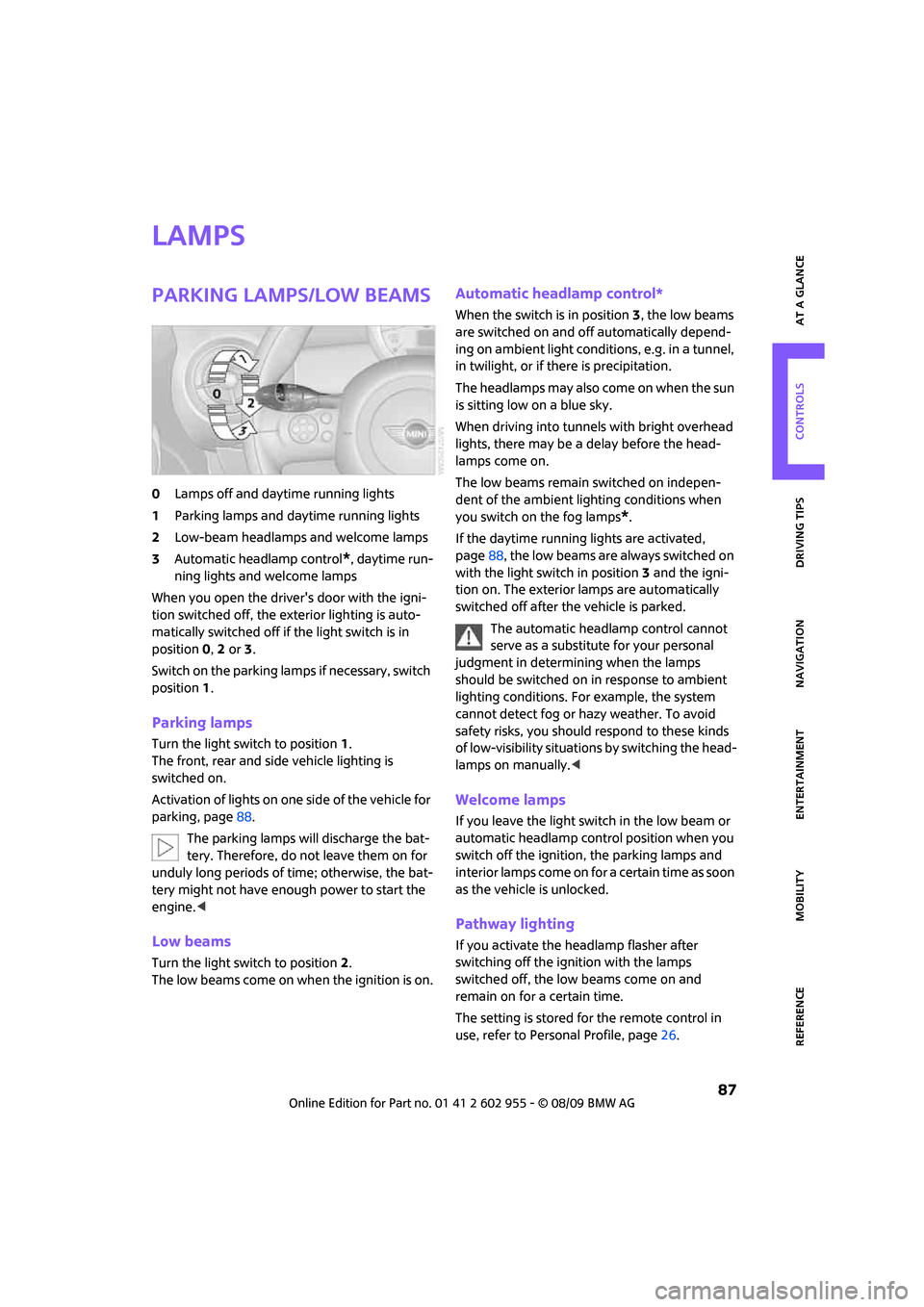
0Lamps off and daytime running lights
1Parking lamps and daytime running lights
2Low-beam headlamps and welcome lamps
3Automatic headlamp control
*, daytime run-
ning lights and welcome lamps
When you open the driver's door with the igni-
tion switched off, the exterior lighting is auto-
matically switched off if the light switch is in
position 0, 2 or 3.
Switch on the parking lamps if necessary, switch
position 1.
Parking lamps
Turn the light switch to position 1.
The front, rear and side vehicle lighting is
switched on.
Activation of lights on one side of the vehicle for
parking, page88.
The parking lamps will discharge the bat-
tery. Therefore, do not leave them on for
unduly long periods of time; otherwise, the bat-
tery might not have enough power to start the
engine.<
Low beams
Turn the light switch to position 2.
The low beams come on when the ignition is on.
Automatic headlamp control*
When the switch is in position3, the low beams
are switched on and off automatically depend-
ing on ambient light conditions, e.g. in a tunnel,
in twilight, or if there is precipitation.
The headlamps may also come on when the sun
is sitting low on a blue sky.
When driving into tunnels with bright overhead
lights, there may be a delay before the head-
lamps come on.
The low beams remain switched on indepen-
dent of the ambient lighting conditions when
you switch on the fog lamps
*.
If the daytime running lights are activated,
page88, the low beams are always switched on
with the light switch in position 3 and the igni-
tion on. The exterior lamps are automatically
switched off after the vehicle is parked.
The automatic headlamp control cannot
serve as a substitute for your personal
judgment in determining when the lamps
should be switched on in response to ambient
lighting conditions. For example, the system
cannot detect fog or hazy weather. To avoid
safety risks, you should respond to these kinds
of low-visibility situations by switching the head-
lamps on manually.<
Welcome lamps
If you leave the light switch in the low beam or
automatic headlamp control position when you
switch off the ignition, the parking lamps and
interior lamps come on for a certain time as soon
as the vehicle is unlocked.
Pathway lighting
If you activate the headlamp flasher after
switching off the ignition with the lamps
switched off, the low beams come on and
remain on for a certain time.
The setting is stored for the remote control in
use, refer to Personal Profile, page26.
Page 91 of 230
MOBILITYAT A GLANCE CONTROLS DRIVING TIPS ENTERTAINMENT
89
NAVIGATION REFERENCE
Switching off
Press the lever up or down to the pressure point.
Fog lamps*
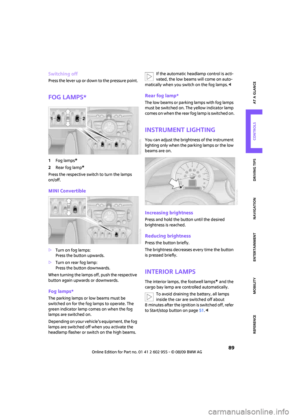
1Fog lamps*
2Rear fog lamp*
Press the respective switch to turn the lamps
on/off.
MINI Convertible
>Turn on fog lamps:
Press the button upwards.
>Turn on rear fog lamp:
Press the button downwards.
When turning the lamps off, push the respective
button again upwards or downwards.
Fog lamps*
The parking lamps or low beams must be
switched on for the fog lamps to operate. The
green indicator lamp comes on when the fog
lamps are switched on.
Depending on your vehicle's equipment, the fog
lamps are switched off when you activate the
headlamp flasher or switch on the high beams.If the automatic headlamp control is acti-
vated, the low beams will come on auto-
matically when you switch on the fog lamps.<
Rear fog lamp*
The low beams or parking lamps with fog lamps
must be switched on. The yellow indicator lamp
comes on when the rear fog lamp is switched on.
Instrument lighting
You can adjust the brightness of the instrument
lighting only when the parking lamps or the low
beams are on.
Increasing brightness
Press and hold the button until the desired
brightness is reached.
Reducing brightness
Press the button briefly.
The brightness decreases every time the button
is pressed briefly.
Interior lamps
The interior lamps, the footwell lamps* and the
cargo bay lamp are controlled automatically.
To avoid draining the battery, all lamps
inside the car are switched off about
8 minutes after the ignition is switched off, refer
to Start/stop button on page51.<