ECO mode MINI Hardtop 2 Door 2015 Owner's Manual (Mini Connected)
[x] Cancel search | Manufacturer: MINI, Model Year: 2015, Model line: Hardtop 2 Door, Model: MINI Hardtop 2 Door 2015Pages: 244, PDF Size: 11.11 MB
Page 6 of 244
Addendum
9.At page 174, under the heading “Pressure
specifications,” the sentence beginning,
“Pressure specifications apply to approved
tire sizes …” should be disregarded.
10. At page 181, under the heading: “Moun-
ting,” the paragraph beginning, “Have
mounting and balancing …” should be dis-
regarded and the following text should be
read in lieu thereof: “BMW recommends that
you have mounting and balancing perfor-
med by your service center or a tire moun-
ting specialist.”
11. At page 181, under the heading: “Approved
wheels and tires,” the term “Approved”
should be disregarded and in lieu thereof,
the term “Recommended” should be read in
its place. In addition, the text of that section
should be disregarded and the following
text should be read in lieu thereof:
The manufacturer of your vehicle strongly
suggests that you use wheels and tires that
have been recommended by the vehicle
manufacturer for your vehicle type; other-
wise, for example, despite having the same
official size ratings, variations can lead to
body contact and with it, the risk of severe
accidents.
The manufacturer of your vehicle does not
evaluate non-recommended wheels and ti-
res to determine if they are suitable for use
on your vehicle.
12. At page 186, under the heading: “Snow
Chains,” the paragraph beginning, “Only
certain fine-link snow chains …” should be
disregarded and the following text should
be read in lieu thereof:
Only certain types of fine-link snow chains
have been tested by the manufacturer of
your vehicle and are determined by the ma-
nufacturer of your vehicle to be road safe
and are recommended by the manufacturer
of your vehicle.
Information about recommended snow
chains is available from a service center.
13. At page 188, under the heading “Hood,” the
sentence beginning, “If you are unfamiliar”
should be disregarded.
14. At page 192, under the heading: “Engine oil
change,” the text should be disregarded and
in lieu thereof should be read as follows:
MINI recommends that you have the oil
changed at your MINI dealer's service center
or at another service center that has trained
personnel that can perform the work in ac-
cordance with MINI specifications.
15. At page 195, under the heading: “Service
and Warranty Information Booklet for US
Models and Warranty and Service Guide
Booklet for Canadian Models,” the second
paragraph should be disregarded and the
following text read in lieu thereof:
The manufacturer of your vehicle recom-
mends that you have maintenance and re-
pair performed by your MINI dealer's service
center or another service center or repair
shop that employs trained personnel that
can perform maintenance and repair work
on your vehicle in accordance with MINI
specifications. The manufacturer of your ve-
hicle recommends that you maintain re-
cords of all maintenance and repair work
performed on your vehicle.
16. At page 207, under the “Battery replace-
ment” section, the text should be disregar-
ded and in lieu thereof the following text
should be read:
Use of recommended vehicle batteries
The manufacturer of your vehicle recom-
mends that you use vehicle batteries that it
has tested and recommends for use in your
vehicle; otherwise the vehicle could be da-
maged and systems or functions may not be
fully available.
After a battery replacement, the manufactu-
rer of your vehicle recommends that you
have the battery registered on your vehicle
by a service center to ensure that all comfort
functions are fully available, and that any
Online Edition for Part no. 01 40 2 961 168 - II/15
Page 11 of 244

Status of the Owner's
Manual
Basic information
The manufacturer of your vehicle pursues a
policy of constant development that is con‐
ceived to ensure that our vehicles continue to
embody the highest quality and safety stan‐
dards. In rare cases, therefore, the features de‐
scribed in this Owner's Manual may differ from
those in your vehicle.
Updates made after the editorial
deadline
Any updates made after the editorial deadline
can be found in the appendix of the printed
Owner's Handbook for Vehicle.
Own safety
Manufacturer The manufacturer of this MINI is Bayerische
Motoren Werke Aktionengesellschaft, BMW AG.
Warranty
Your vehicle is technically configured for the
operating conditions and registration require‐
ments applying in the country of first delivery -
homologation. If your vehicle is to be operated
in a different country it might be necessary to
adapt your vehicle to potentially differing oper‐
ating conditions and permit requirements. If
your vehicle does not comply with the homolo‐
gation requirements in a certain country you
cannot lodge warranty claims for your vehicle
there. Further information can be obtained
from your Service Centre.
Maintenance and repairs
Advanced technology, e.g., the use of modern
materials and high-performance electronics,
requires suitable maintenance and repair work.Therefore, have this work performed only by a
MINI service center or a workshop that works
according to the manufacturer's repair proce‐
dures for the MINI with respectively trained
personnel.
If work is not carried out properly, there is a
danger of subsequent damage and related
safety hazards.
Parts and Accessories
For your own safety, it is recommended that
you use genuine parts and accessories ap‐
proved by MINI. When you purchase accesso‐
ries tested and approved by MINI and Genuine
MINI Parts, you simultaneously acquire the as‐
surance that they have been thoroughly tested
by MINI to ensure optimum performance when
installed on your vehicle. MINI warrants these
parts to be free from defects in material and
workmanship. MINI will not accept any liability
for damage resulting from installation of parts
and accessories not approved by MINI. MINI
cannot test every product made by other man‐
ufacturers to verify if it can be used on a MINI
safely and without risk to either the vehicle, its
operation, or its occupants. Genuine MINI Parts,
MINI Accessories and other products approved
by MINI, together with professional advice on
using these items, are available from all MINI
centers. Installation and operation of non-MINI
approved accessories such as alarms, radios,
amplifiers, radar detectors, wheels, suspension
components, brake dust shields, telephones,
including operation of any mobile phone from
within the vehicle without using an externally
mounted antenna, or transceiver equipment,
for instance, CBs, walkie-talkies, ham radios or
similar accessories, may cause extensive dam‐
age to the vehicle, compromise its safety, inter‐
fere with the vehicle's electrical system or af‐
fect the validity of the MINI Limited Warranty.
See your MINI center for additional informa‐
tion. Maintenance, replacement, or repair of
the emission control devices and systems may
be performed by any automotive repair estab‐Seite 7Notes7
Online Edition for Part no. 01 40 2 961 168 - II/15
Page 12 of 244

lishment or individual using any certified auto‐
motive part.
California Proposition 65 Warning California laws require us to state the following
warning:
Engine exhaust and a wide variety of automo‐
bile components and parts, including compo‐
nents found in the interior furnishings in a vehi‐
cle, contain or emit chemicals known to the
State of California to cause cancer and birth de‐
fects and reproductive harm. In addition, cer‐
tain fluids contained in vehicles and certain
products of component wear contain or emit
chemicals known to the State of California to
cause cancer and birth defects or other repro‐
ductive harm. Battery posts, terminals and re‐
lated accessories contain lead and lead com‐
pounds. Wash your hands after handling. Used
engine oil contains chemicals that have caused
cancer in laboratory animals. Always protect
your skin by washing thoroughly with soap and
water.
Service and warranty
We recommend that you read this publication
thoroughly. Your vehicle is covered by the fol‐
lowing warranties:▷New Vehicle Limited Warranty.▷Rust Perforation Limited Warranty.▷Federal Emissions System Defect Warranty.▷Federal Emissions Performance Warranty.▷California Emission Control System Limited
Warranty.
Detailed information about these warranties is
listed in the Service and Warranty Information
Booklet for US models or in the Warranty and
Service Guide Booklet for Canadian models.
Your vehicle has been specifically adapted and
designed to meet the particular operating con‐
ditions and homologation requirements in your
country and continental region in order to de‐
liver the full driving pleasure while the vehicle is
operated under those conditions. If you wish to
operate your vehicle in another country or re‐
gion, you may be required to adapt your vehi‐
cle to meet different prevailing operating con‐
ditions and homologation requirements. You
should also be aware of any applicable war‐
ranty limitations or exclusions for such country
or region. In such case, please contact Cus‐
tomer Relations for further information.
Maintenance
Maintain the vehicle regularly to sustain the
road safety, operational reliability and the New
Vehicle Limited Warranty.
Specifications for required maintenance meas‐
ures:▷MINI Maintenance system▷Service and Warranty Information Booklet
for US models▷Warranty and Service Guide Booklet for
Canadian models
If the vehicle is not maintained according to
these specifications, this could result in serious
damage to the vehicle. Such damage is not
covered by the MINI New Vehicle Limited War‐
ranty.
Data memory
Many electronic components on your vehicle
are equipped with data memories that tempo‐
rarily or permanently store technical informa‐
tion about the condition of the vehicle, events
and faults. This technical information generally
records the state of a component, a module, a
system or the environment:
▷Operating mode of system components, fill
levels for instance.▷Status messages for the vehicle and from its
individual components, e.g., wheel rotation
speed/vehicle speed, deceleration, trans‐
verse acceleration.Seite 8Notes8
Online Edition for Part no. 01 40 2 961 168 - II/15
Page 26 of 244
2."Touchpad"3.Select the desired function.▷"Speller": enter letters and numbers.▷"Interactive map": viewing the interac‐
tive map.▷"Audio feedback": pronounces entered
letters and numbers.
Entering letters and numbers
Entering letters requires some practice at the
beginning. When entering, pay attention to the
following:
▷For the input of upper/lower case letters
and numbers, it may be necessary to switch
via the controller to the corresponding In‐
put mode, refer to page 25, e.g. when the
spelling of upper and lower case letters is
identical.▷Enter characters as they are displayed on
the Control Display.▷Always enter associated characters, such as
accents or periods so that the letter can be
clearly recognized. Possible input depends
on the set language. Where necessary, en‐
ter special characters via the controller.▷To delete a character, slide to the left on
the touchpad.▷To enter a blank space, slide to the right in
the center of the touchpad.▷To enter a hyphen, slide to the right in the
upper area of the touchpad.▷To enter an underscore, swipe to the right
in the lower area of the touchpad.
Operating the interactive map
The interactive map in the navigation system
can be moved via the touchpad.
FunctionControlsInteractive map.Swipe into respective
direction.Enlarge/shrink in‐
teractive map.Drag in or out on the
touchpad with fingers.Display menu.Tap once.
Changing settings
You may change control display settings via
touchpad. Swipe left or right accordingly.
Example: setting the clock
Setting the clock
On the Control Display:
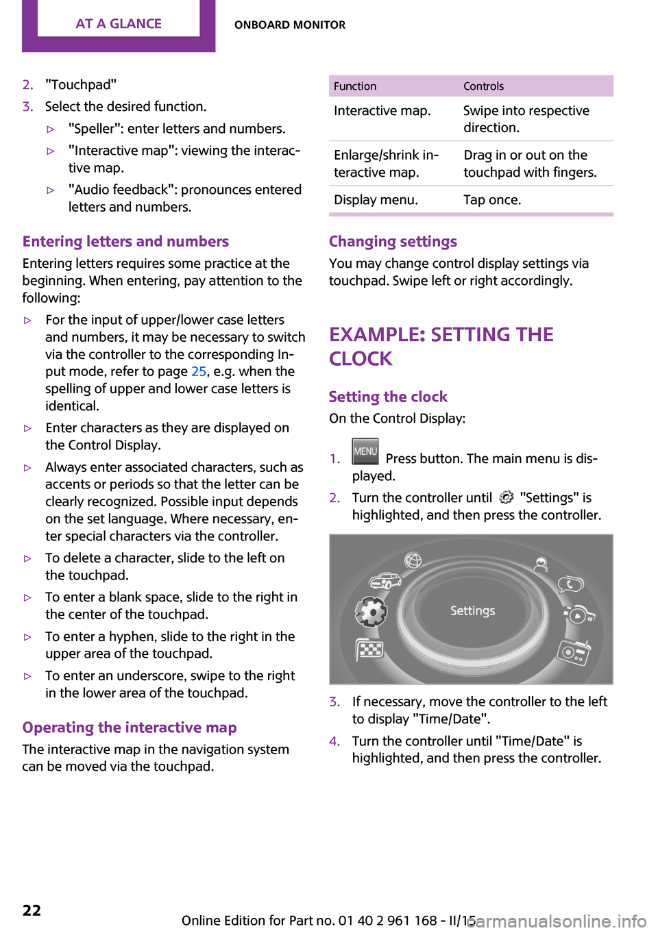
1. Press button. The main menu is dis‐
played.2.Turn the controller until "Settings" is
highlighted, and then press the controller.3.If necessary, move the controller to the left
to display "Time/Date".4.Turn the controller until "Time/Date" is
highlighted, and then press the controller.Seite 22AT A GLANCEOnboard monitor22
Online Edition for Part no. 01 40 2 961 168 - II/15
Page 41 of 244
This can be helpful for securing and retrieving
personal settings, before delivering the vehicle
to a workshop, e.g. Profiles can be taken to an‐
other vehicle equipped with the Personal Pro‐
file function.
Export is made via the USB port to a USB de‐
vice.
Popular file systems for USB devices are sup‐
ported. FAT32 and exFAT are the recom‐
mended formats for profile export. Other for‐
mats may not support the export.1. "Settings"2."Profiles"3."Export profile"4."USB device"
Importing profiles
Profiles stored on a USB device can be im‐
ported via the USB interface.
Existing settings are overwritten with the im‐
ported profile.
1. "Settings"2."Profiles"3."Import profile"4."USB device"
Using the guest profile
The guest profile is for individual settings that
are saved in none of the three personal profiles.
This can be useful for drivers who are using the
vehicle temporarily and do not have their own
profile.
1. "Settings"2."Profiles"3."Guest"4.Adjust the settings.
The guest profile cannot be renamed. It is not
assigned to the current remote control.
Display profile list during start
The profile list can be displayed during each
start to select the desired profile.1. "Settings"2."Profiles"3.Open "Options".4."Display user list at startup"
Using the remote con‐
trol
Note Take the remote control with you
People or animals left unattended in a
parked vehicle can lock the doors from the in‐
side. Always take the remote control with you
when leaving the vehicle so that the vehicle
can then be opened from the outside. ◀
Unlocking Press button on the remote control.
▷The vehicle is unlocked.▷Interior lamps and courtesy lamps are acti‐
vated. This function is not available, if the
interior lamps were switched off manually.▷The welcome lamps are switched on, if this
function was activated.▷Exterior mirrors folded through convenient
closing are folded open.
On 3-door models:
Press button on the remote control
twice in direct succession.
When the door is opened, the window is low‐
ered more to make it easier to enter the vehi‐
cle.
You can set how the vehicle is to be unlocked.
Create the settings, refer to page 42.
Seite 37Opening and closingCONTROLS37
Online Edition for Part no. 01 40 2 961 168 - II/15
Page 42 of 244
The alarm system, refer to page 43, is dis‐
armed.
Convenient opening Press and hold this button on the re‐
mote control after unlocking.
The windows and the glass sunroof are opened,
as long as the button on the remote control is
pressed.
Locking Locking from the outside
Do not lock the vehicle from the outside
with people inside the car, as the vehicle can‐
not be unlocked from inside without special
knowledge. ◀
The driver's door must be closed. Press button on the remote control.
The alarm system, refer to page 43, is armed.
If the vehicle horn honks twice when you lock
the car, this means that the engine or ignition is
still switched on. In this case, the engine or ig‐
nition must be switched off by means of the
Start/Stop button.
Switching on interior lights and
courtesy lights
Press button on the remote control
with the vehicle locked.
This function is not available, if the interior
lamps were switched off manually.
If the button is pressed within 10 seconds of
when the vehicle was locked Interior motion
sensor and tilt alarm sensor of the anti-theft
warning system, refer to page 44, are turned
off. After locking, wait 10 seconds before press‐
ing the button again.Panic mode
You can trigger the alarm system if you find
yourself in a dangerous situation.
Press button on the remote control for
at least 3 seconds.
To switch off the alarm: press any button.
Unlock the tailgate Press button on the remote control for
approx. 1 second.
The tailgate opens slightly, regardless of whether the vehicle was previously locked or
unlocked.
Depending on the features and the country
version, it is also possible to have door un‐
locked. Create the settings, refer to page 42.
If the doors were not unlocked, the tailgate is
locked again as soon as it closes.
Do not place the remote control in the
cargo area
Take the remote control with you and do not
leave it in the cargo area; otherwise, the re‐
mote control is locked inside the vehicle when
the tailgate is closed. ◀
Provide edge protection
Sharp objects or those with edges can hit
the rear window while driving and damage the
heat conductors of the rear window. Provide edge protection. ◀
Malfunction Remote control detection by the vehicle can
among others be malfunctioning under the fol‐
lowing circumstances:▷The battery of the remote control is dis‐
charged. Replace the battery, refer to
page 34.▷Interference of the radio connection from
transmission towers or other equipment
with high transmit power.Seite 38CONTROLSOpening and closing38
Online Edition for Part no. 01 40 2 961 168 - II/15
Page 47 of 244
Tailgate
Depending on optional features and country
version, this setting is not offered in some
cases.1. "Settings"2."Doors/key"3. Select the symbol.4.Select the desired function.▷"Tailgate"
Only the tailgate is unlocked.▷"Tailgate + door(s)"
The tailgate and the doors are un‐
locked.
Locking
The settings are saved in the active profile. Per‐
sonal Profile, refer to page 35.
1. "Settings"2."Doors/key"3.Select desired setting.▷"Lock if no door is opened"
The vehicle locks automatically after a
short period of time if no door is
opened.▷"Lock after start driving"
The vehicle locks automatically after
you drive off.
Confirmation signals from the vehicle
1. "Settings"2."Doors/key"3.Select desired setting.▷"Acoustic sig. lock/unlock"
Unlocking is signaled by one honk of
the horn.▷"Flash when lock/unlock"
Unlocking is signaled by two flashes,
locking by one.Alarm system
The concept
When the vehicle is locked, the vehicle alarm
system responds to:▷Opening a door, the hood or the tailgate.▷Movements in the vehicle interior▷Changes in the vehicle tilt, e. g., during at‐
tempts at stealing a wheel or when towing
the car.▷Disconnected battery voltage.
The alarm system briefly signals tampering:
▷Acoustic alarm.▷By switching on the hazard warning system.▷By flashing the daytime running lights.
Arming and disarming the alarm system
When you lock or unlock the vehicle, either
with the remote control or via the Comfort Ac‐
cess, the alarm system is armed or disarmed at
the same time.
Door lock and armed alarm system
The alarm system is triggered when the door is
opened, when the vehicle is unlocked via the
door lock.
Switch off the alarm, refer to page 44.
Tailgate and armed alarm system The tailgate can be opened even when the
alarm system is armed.
After the tailgate is closed, it is locked and monitored again when the doors are locked.
The hazard warning system flashes once.
Panic mode
You can trigger the alarm system if you find
yourself in a dangerous situation.
Press button on the remote control for
at least 3 seconds.
Seite 43Opening and closingCONTROLS43
Online Edition for Part no. 01 40 2 961 168 - II/15
Page 50 of 244

2.Pull the switch past the resistance point
again within approx. 4 seconds and hold it
there.
The window closes without jam protection.
On 5-door models: safety switch The safety switch in the driver's door can be
used to prevent children, e.g., from opening
and closing the rear windows using the
switches in the rear.
Switching on and off Press button.
The LED lights up if the safety function
is switched on.
Safety switch for rear operation
Press the safety switch when transporting
children in the rear; otherwise, injury may result
if the windows are closed without supervi‐
sion. ◀
Panoramic glass sun‐
roof
Hints Keep the closing path clear
Monitor closing and make sure that the
closing path of the glass sunroof is clear; other‐
wise, injuries may result. ◀
Take the remote control with you
Take the remote control with you when
leaving the vehicle so that children, e.g., cannot
operate the glass sunroof and injure them‐
selves. ◀
At a glance
Tilting the glass sunroof
Press back the reel up to or be‐
yond the resistance point and re‐
lease it.
The glass sunroof is raised.
Opening glass sunroof
When the glass sunroof is closed Press the reel back beyond the
resistance point and release it
twice.
The glass sunroof is opened.
Pressing the reel again stops the
motion.
With the glass sunroof completely
raised
▷Slide reel back to the resist‐
ance point and hold.
The glass sunroof is opened
as long as the reel is pressed.▷Press the reel back beyond
the resistance point and re‐
lease it.
The glass sunroof is opened.
Pressing the reel again stops
the motion.Seite 46CONTROLSOpening and closing46
Online Edition for Part no. 01 40 2 961 168 - II/15
Page 71 of 244
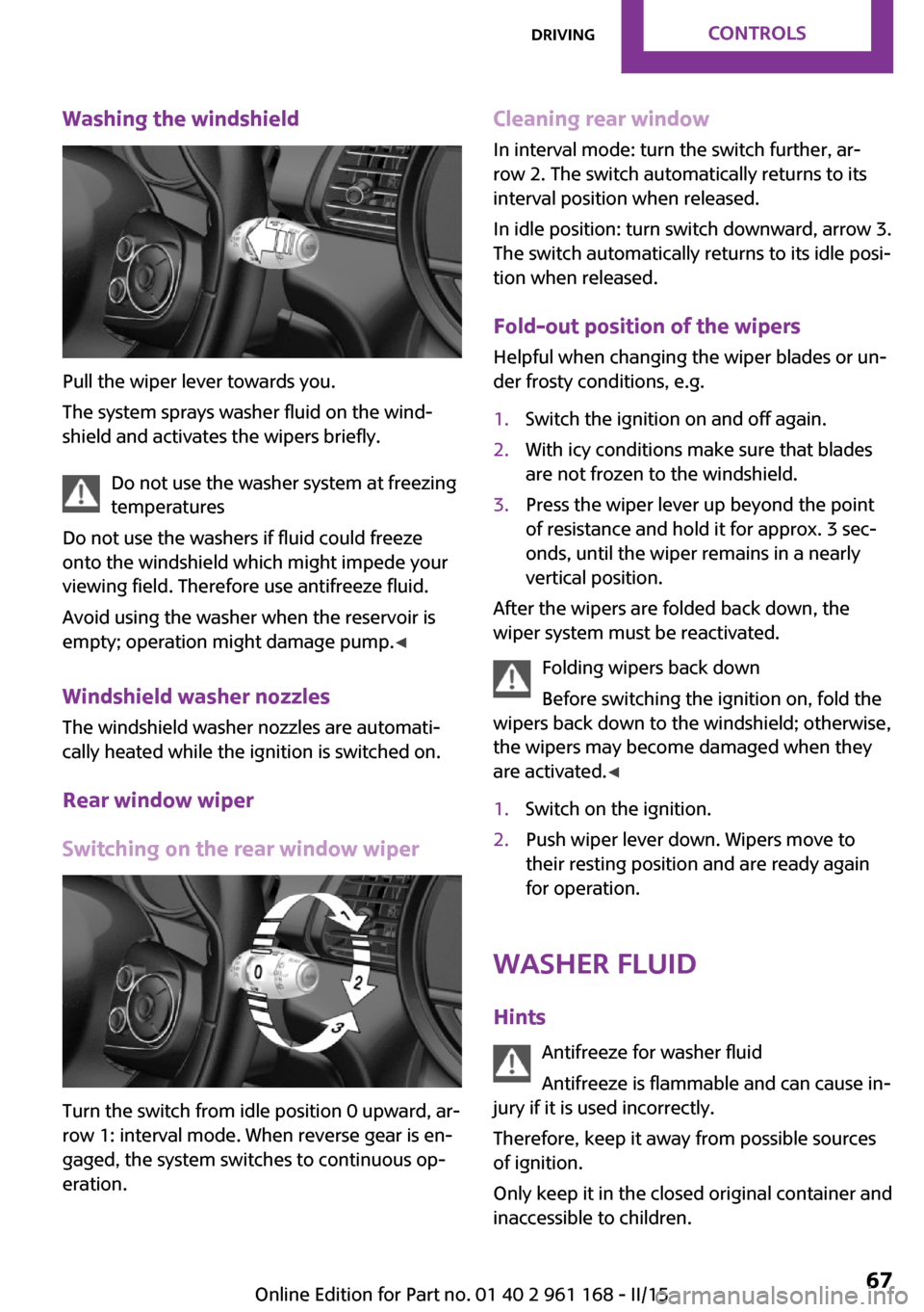
Washing the windshield
Pull the wiper lever towards you.
The system sprays washer fluid on the wind‐
shield and activates the wipers briefly.
Do not use the washer system at freezing
temperatures
Do not use the washers if fluid could freeze
onto the windshield which might impede your
viewing field. Therefore use antifreeze fluid.
Avoid using the washer when the reservoir is
empty; operation might damage pump. ◀
Windshield washer nozzles The windshield washer nozzles are automati‐
cally heated while the ignition is switched on.
Rear window wiper
Switching on the rear window wiper
Turn the switch from idle position 0 upward, ar‐
row 1: interval mode. When reverse gear is en‐
gaged, the system switches to continuous op‐
eration.
Cleaning rear window
In interval mode: turn the switch further, ar‐
row 2. The switch automatically returns to its
interval position when released.
In idle position: turn switch downward, arrow 3.
The switch automatically returns to its idle posi‐
tion when released.
Fold-out position of the wipers
Helpful when changing the wiper blades or un‐
der frosty conditions, e.g.1.Switch the ignition on and off again.2.With icy conditions make sure that blades
are not frozen to the windshield.3.Press the wiper lever up beyond the point
of resistance and hold it for approx. 3 sec‐
onds, until the wiper remains in a nearly
vertical position.
After the wipers are folded back down, the
wiper system must be reactivated.
Folding wipers back down
Before switching the ignition on, fold the
wipers back down to the windshield; otherwise,
the wipers may become damaged when they
are activated. ◀
1.Switch on the ignition.2.Push wiper lever down. Wipers move to
their resting position and are ready again
for operation.
Washer fluid
Hints Antifreeze for washer fluid
Antifreeze is flammable and can cause in‐
jury if it is used incorrectly.
Therefore, keep it away from possible sources
of ignition.
Only keep it in the closed original container and
inaccessible to children.
Seite 67DrivingCONTROLS67
Online Edition for Part no. 01 40 2 961 168 - II/15
Page 73 of 244
KickdownKickdown is used to achieve maximum driving
performance. Step on the accelerator pedal be‐
yond the resistance point at the full throttle po‐
sition.
Engaging a selector lever position Press on the brake pedal until you start
driving
To prevent the vehicle from creeping after you
select a gear, maintain pressure on the brake
pedal until you are ready to start. ◀
The selector lever can only be taken out of se‐
lector lever position P if the ignition is on or the
engine is running.
With the vehicle is stationary, press on the
brake pedal before shifting out of selector lever
position P or N; otherwise, the selector lever is
blocked: shift lock.
A lock prevents inadvertent shifting into selec‐
tor lever position P or R.
Canceling the lock
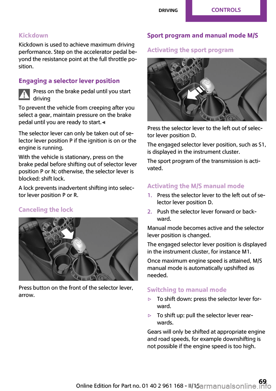
Press button on the front of the selector lever,
arrow.
Sport program and manual mode M/S
Activating the sport program
Press the selector lever to the left out of selec‐
tor lever position D.
The engaged selector lever position, such as S1,
is displayed in the instrument cluster.
The sport program of the transmission is acti‐
vated.
Activating the M/S manual mode
1.Press the selector lever to the left out of se‐
lector lever position D.2.Push the selector lever forward or back‐
ward.
Manual mode becomes active and the selector
lever position is changed.
The engaged selector lever position is displayed
in the instrument cluster, for instance M1.
Once maximum engine speed is attained, M/S
manual mode is automatically upshifted as
needed.
Switching to manual mode
▷To shift down: press the selector lever for‐
ward.▷To shift up: pull the selector lever rear‐
wards.
Gears will only be shifted at appropriate engine
and road speeds, for example downshifting is
not possible if the engine speed is too high.
Seite 69DrivingCONTROLS69
Online Edition for Part no. 01 40 2 961 168 - II/15